
Chapter 5
Droplets Between Two Non-parallel Planes: From Tapered Planes to Wedges
5.1 Abstract
In this chapter, we focus on the behavior of a droplet or a liquid plug placed between two non-parallel plates. It is assumed that the droplet is sufficiently small that gravitational forces can be neglected (droplet Bond number smaller than 1). The case of tapered plates is first investigated. It is shown that, if the walls are perfectly smooth, e.g. there is no pinning hysteresis, a wetting droplet is not at equilibrium in such a geometry. The conventional Hauksbee’s formulation for wetting walls is presented, and a generalization for any wall wetting property (two wetting walls, two non-wetting walls, wetting and non-wetting walls) is derived. In a second part, the focus is on the Concus-Finn relations for a wedge, which governs the location of the droplet in the wedge. A generalization to different wall wetting properties is presented.
5.2 Droplet Self-motion Between Two Non-parallel Planes
It was first observed by Hauksbee [1,2] that a water plug limited by two non-parallel wetting plates – hydrophilic for a water droplet or lyophilic for any liquid – moves towards the narrow gap region. A sketch of the plug is shown in figure 5.1.
Figure 5.1 Sketch of a liquid plug between two wetting plates. The contact angle is θ < 90° and the plug is not at equilibrium: it moves in the direction of the smaller cross-section. Note that the Laplace pressures are negative in such a case.

It was shown in Chapter 2 that the minimum energy configuration is a spherical droplet with the proper contact angles, which can only happen if the plates are hydrophobic enough, or else the liquid goes to the corner of the wedge. This section takes a force-based approach to arrive at the same conclusions, and although the arguements here are not as rigorous, they do give insight on the dynamics of what happens.
In this section, it is demonstrated how Laplace’s law furnishes a clear explanation of droplet motion. Moreover, the analysis of self-motion of a droplet between two non-parallel plates is extended to any contact angle. It is shown that there exist a critical contact angle θ* larger than π/2 above which the droplet stays away from the corner. Below this critical angle, the droplet moves towards the corner, in agreement with Hauksbee’s analysis. It is shown also that if the Young contact angles of the liquid with the plates are different, it is their average value that has to be taken into account.
5.2.1 Identical Young Contact Angle with Both Plates
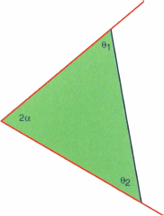
Let us assume a geometry where the two plates form a wedge of half-angle a in the vertical plane. The different possible geometries, depending on the concavity or convexity of the interface are shown in figure 5.2.
Figure 5.2 The different cases of the interfaces. α is the wedge half-angle, L is the distance from the wedge vertex to the center of curvature, R is the radius of curvature, and θ is the liquid contact angle.

In our notations, R is always positive. L is the distance from the dihedral to the center of curvature. Let us write Laplace’s law for the left interface (index 1). The curvature of the interface is determined by the two curvature radii in two perpendicular planes. Let us consider the vertical and horizontal planes, with the curvature radii R1 and RH
where c1 has the value 1 or -1 depending whether the interface is concave or convex relative to the liquid phase. In case (2) of figure 5.2, the interface is concave and c1 = 1, and in case (4), the interface is convex and c1 = - 1. Using the Law of Sines we find
(5.2) ![]()
Likewise, case (4) gives
Independently of the concavity, relation (5.1) becomes
For the right side interface (index 2)
(5.5) ![]()
Because the droplet has a circular shape in the horizontal plane, the curvature radius RH is the same for both interfaces. The same reasoning as done for the left side leads to
where c2 has the same definition as c1.
By subtracting the two relations (5.4) and (5.6), the horizontal curvature radius RH vanishes, and the pressure difference is
Inspection of (5.7) immediately shows that if the centers of curvature coincide, L1 = L2, then the droplet is in equilibrium. This obviously agrees with the result from Chapter 2 that a sphere is a stable configuration. Clearly this can happen only for hydrophobic planes; for hydrophilic planes, the centers of curvature are outside the drop on opposite sides, L1 > L2, and the force is always towards the narrow part of the wedge. Returning to the hydrophobic case, if the drop is flatter than a sphere, then L1 > L2, and the net force is towards the opening of the wedge, recalling cos α < 0 here. If the drop is stretched from a sphere, the force is narrowward.
It can be shown that when the droplet moves towards the corner it accelerates. As the droplet moves to the right, L1 will decrease much faster than L2 as the drop stretches out, and the force increases.
5.2.2 Different Young Contact Angles
What happens if the two planes have a different contact angle with the liquid? Let us denote by θ1 and θ2 the two contact angles. The behavior turns out to be the same as with a common contact angle, but the common contact angle θ has to be replaced by the average θ = (θ1 + θ2)/2.
There are three possible stable configurations: a spherical bridge between the planes that does not wet the dihedral (high contact angles), a spherical wedge that does wet the dihedral (medium contact angles), and a long filament (low contact angles).
The dividing line between the bridge and wetting wedge comes when the sphere of the droplet is just tangent to the junction of the planes, as shown in figure 5.3. A little geometry with some isosceles triangles defined by some radii shows that the angles satisfy
Figure 5.3 Critical contact angles for a spherical drop wetting the dihedral line of a wedge.

(5.8) ![]()
or
(5.9) ![]()
The dividing line between the wetting wedge and filaments is the Concus-Finn criterion, which happens when the liquid/air surface is planar, so a cross-section is triangular, as shown in figure 5.4. The critical condition may be written as the standard Euclidean angle sum of a triangle:
Figure 5.4 Critical Concus-Finn contact angles for the formation of filaments; the dihedral angle and the contact angles add to π, the liquid surface is flat, and there is zero pressure difference across the surface.
(5.10) ![]()
or
(5.11) ![]()
The contact angles here necessarily make it so the total of the plane contact energy and the liquid/air surface energy is exactly zero. This can most directly be seen by dropping an altitude from the wedge vertex to the planar surface. If the wetted plane lenghts are b1 and b2 respectively, and c the length of the planar surface, then projecting b1 and b2 down to c gives
(5.12) ![]()
which is exactly the condition for the total surface tension energy to be zero:
(5.13) ![]()
For contact angles smaller that the Concus-Finn critical condition, the reason filaments grow arbitrarily may be deduced from the fact that the total surface contact energy is negative. The liquid/air surface must be concave (since the Concus-Finn critical condition is that it is flat), which means the liquid has negative pressure. Pressure being the rate of change of energy with respect to volume, that means the surface energy must be negative since the surfaces increase as volume increases. Now consider a fixed volume of liquid contemplating spreading into a filament. Narrowing into a filament greatly increases the surface-to-volume ratio, and since the surface energy is negative, spreading into a filament is favored.
Another perspective on the two critical conditions is to consider the tangent plane where a wetting wedge surface meets the dihedral line. For the wedge to exist, it must be possible to have a single tangent plane that meets both the contact angle conditions simultaneously. This turns out to be possible exactly between the two critical conditions found above, so the wedge can wet for
(5.14) ![]()
Figure 5.5 shows a graphical representation of the various possibilities.
Figure 5.5 Phase plane for the different types of stable behaviors of a drop between nonparallel planes.

5.2.3 Numerical Simulation – 2D and 3D Cases
Consider two plates making a half-angle of 2.85°, and consider the two following cases: (1) water droplet located between two hydrophilic solid plates (θ = 80°), and (2) water droplet located between two hydrophobic solid plates (θ = 130°). We can use Surface Evolver, and show that the results agree with the theoretical analysis of the preceding sections, i.e. the droplet moves towards the corner in the first (hydrophilic) case, and stays away from the corner in the second case (hydrophobic).
The motion of the droplet is illustrated in the figures 5.6 to 5.9, depending on the values of the contact angles. The contact angles are 80°/80° in figure 5.6, 130°/130° in figure 5.7, 80°/130° in figure 5.8 and 105°/140° in figure 5.9.
Figure 5.6 Evolver simulation of a wetting droplet moving towards the smaller cross-section area: the black line is a fixed mark for visualization and the upper plate has been dematerialized for better visibility.

Figure 5.7 Evolver simulation of a non-wetting droplet moving towards the larger cross-section area.

Figure 5.8 Evolver simulation of a droplet with different Young contact angles with both planes (θlower = 80°, θupper = 130°); in this case, the initial droplet is stretched, so it moves towards the smaller cross-section area.

Figure 5.9 Evolver simulation of a droplet with different Young contact angles with both planes (θlower = 105°, θupper = 140°); in this case, the initial droplet is compressed, so it moves towards the larger cross-section area.

5.2.4 A Reciprocal to the Hauksbee Problem
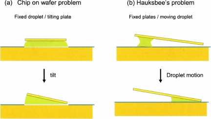
In the chapter 11 (Microelectronics), we present an analysis of the tilt of a chip placed on a sessile water droplet deposited on a hydrophilic pad on a wafer [3]. It is shown that the chip slowly tilts until a wedge is formed. The analysis is closely related to the Hauksbee problem. In fact it can be seen as a reciprocal to the Hauksbee problem (fig. 5.10). In the first case, it has been demonstrated here that a wetting droplet moves towards the dihedral edge of the two fixed planes. In the second case, the upper plate tilts on top of the fixed droplet until a liquid wedge is formed. These two reciprocal properties are linked by the observation that the minimal free surface area has a wedge shape [4].
Figure 5.10 Sketches of the “Chip on wafer” tilt instability (a), and of Hauksbee’s problem (b). In both cases, the minimal surface for the droplet is reached when the droplet is located in the dihedral corner.
5.2.5 Example of Tapered System for Passive Pumping in Fuel Cells
Recently, Litterst et al. and Paust et al. have given an interesting application of the Hauksbee analysis [5, 6]. Their application concerns passive pumping for methanol-powered fuel cells. In electronics, direct micro methanol fuel cells (μMFCs) are attractive due to the high density of methanol, fast refueling, and extremely long shelf life. Therefore, they are promising candidates for powering small electronic devices. However, a significant challenge is the removal of carbon dioxide bubbles from the anode. At the anode, CO2 bubbles are generated as a reaction product of the methanol oxidation reaction; these bubbles may block channels and cause the μMFC to malfunction. Hence degassing is required. Using tapered channels – as shown in figure 5.11 – bubbles can be removed from the cell; at the same time the extraction of the bubbles from the system contributes to the pumping of the fuel into the cell. A close-up on the tapered plate area is shown in figure 5.12.
Figure 5.11 Sketch of the fuel cell with the tapered plate.

Figure 5.12 Sketch of the passive pumping of CO2 bubbles in a fuel cell.

The physics behind the pumping system is that described earlier in this chapter, except for the fact that the droplet volume is not constant. The walls are treated to be hydrophilic so that the contact angle of the CO2 with the wall is sufficiently above π/2 to obtain the motion away from the dihedral (the planes’ angle is of the order of 1.5° to 3°). At first a bubble grows into the tapered channel (t1 on figure 5.12); it touches the upper channel wall (t2); the bubble right interface grows towards the increasing cross-section of the channel while its left interface stays pinned at the channel entrance (t3); at time t4 the Laplace pressure difference is sufficient to trigger de-pinning and the release of the bubble. The Laplace pressure difference increases because the length L2 in (5.7) is constant and L1 increases: the first, negative term increases (in absolute value) while the positive term decreases, and the absolute value of pressure difference |P1 - P2| increases. Once the droplet has evacuated the channel, the same sequence then restarts.
In their approach, Paust et al. have taken into account a receding and an advancing contact angle with the walls. In such a case, equations (5.3) and (5.6) become
and
However, at the low flow velocities characteristic of this microsystem, the contact angle hysteresis is small and does not significantly affect the droplet motion.
5.2.6 Discussion
We have demonstrated that a droplet between two non-parallel plates is not at equilibrium. There exists a critical angle θ* larger than π/2 below which the droplet moves towards the corner (θ < θ*) and above which the droplet moves away from the corner (θ > θ*). Moreover, a droplet moving towards the corner progressively accelerates while a droplet moving away from the corner decelerates and stops.
Bouasse [7] has remarked that the same type of motion applies for a cone, where the plug moves towards the tip of the cone. In reality, Bouasse used a conical frustum (slice of cone) in order to let the gas escape during plug motion. More recently, Renvoisé et al. have performed a same type of experiment using a narrowing tube with its tapered end pointing upwards, analyzing the balance between capillary force, gravity and shape of the tube [8].
In this section, the wedge half-angle α was supposed relatively small, so that the constant volume can move along a noticeable length between the two planes. In the following section we address the case of a droplet located very close to the groove line. We shall see that the position of the droplet is predicted by the Concus-Finn relations, which indicate the conditions for a droplet to spread like a filament in the corner, or to detach from the corner. In particular, we will show that a sufficiently wetting droplet in a small angle wedge (tapered planes) moves towards the corner, wets the corner and spreads laterally as a filament.
5.3 Droplet in a Corner
In this section we investigate the behavior of a droplet placed very close to the edge of the wedge. Microfluidic channels and chambers are usually etched in silicon, glass, or plastic, and liquids are either aqueous or organic. Hence contact angles can be anywhere in the interval [0, π]. We show that the shape that a droplet takes in a wedge depends on the wedge angle and on the Young contact angle of the liquid with the walls.
5.3.1 Dimensions of the Droplet and Effect of Gravity
Let us investigate first the effect of a corner – or a wedge – on the droplet interface. Take the case of a 90° wedge. The shape of the droplet is shown in figure 5.13, depending on the Bond number Bo = ρgR2/γ, where R is a characteristic dimension of the droplet, which can be scaled as the 1/3 power of the value of the volume of liquid. A small volume droplet of 0.125 μl tends to take the form of a portion of sphere despite the different contact angles on the two planes (the Bond number is of the order of 0.04). A larger droplet of 1.25 μl – Bond number of 4 – is flattened by gravity. In the rest of this chapter we consider droplets sufficiently small not to be affected by gravity.
Figure 5.13 Shape of a liquid drop in a 90° wedge. Left: a small volume droplet of 0.125 μl tends to take the form of a sphere despite the different contact angles on the two planes (the Bond number is of the order of 0.04). Right, a larger droplet of 1.25 μl – Bond number 4 – is flattened by gravity.

5.3.2 Concus-Finn Relations
It has been observed that liquid interfaces in contact with highly wetting solid walls forming a wedge tend to spread in the corner. This behavior results from the fact that the interface curvature is strongly reduced in the corner (in figure 5.14, the vertical curvature radius is small): the Laplace pressure is low in the corner and liquid tends to spread in the corner. Concus and Finn (1969 and 1974) [9] have investigated this phenomenon and they have derived a criterion for capillary motion in the corner of the wedge. If θ is the Young contact angle on both planes and α the wedge half-angle, the condition for capillary self-motion is
Figure 5.14 A liquid interface is lifted in the comer of a wedge made of two wetting plates. This phenomenon is due to the need for a common tangent plane making the proper contact angles on the two walls. The tube-with-wedge on the right has a wedge angle of 2α = 90° and contact angle of 60°.

This case corresponds to wetting walls. Conversely, when the walls are non-wetting the condition for de-wetting of the corner is
In figure 5.15, the Concus-Finn relations have been plotted in a (θ, α) coordinate system. One verifies that, for a flat angle (α = 0°), the Concus-Finn relations reduce to the usual capillary analysis.
Figure 5.15 Plot of the domains of self-motion in a corner, according to the Concus-Finn relations.

5.3.3 Numerical Approach
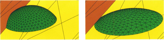
The Concus-Finn relations can be numerically verified using the Surface Evolver software. Figure 5.16 shows the shape taken by a wetting droplet in a 90° wedge according to the contact angle with the walls. Spreading of the liquid in the corner occurs when condition (5.15) is met. If condition (5.15) is not met, the droplet takes a nearly spherical shape.
Figure 5.16 Droplet in a 90° wedge: (a) initial (non-physical) droplet; (b) the droplet spreads in the corner when the contact angles satisfy the Concus-Finn condition (here θ = 45°); (c) the droplet adopts a nearly spherical shape when the Concus-Finn condition is not met (here θ = 80°).

The decrease of the Laplace pressure in the corner mentioned earlier can be checked by plotting the stretching length (length of the groove line in contact with the liquid) versus the contact angle (fig. 5.17).
Figure 5.17 Stretching length of the droplet as a function of the contact angle: the Concus-Finn limit appears as an asymptote.

The second Concus-Finn relation can also be checked numerically. Figure 5.18 shows the shape taken by a non-wetting droplet in a 90° wedge according to the contact angle with the walls. If the contact angles on both planes are larger than 135°, the drop detaches from the corner, and does not wet the corner any more.
Figure 5.18 Droplet in a hydrophobic wedge: (a) initial (non-physical) droplet; (b) the droplet at equilibrium still wets the corner if the second Concus-Finn relation is not satisfied (here θ = 120°); (c) if the contact angle is larger than 135° (here θ = 150°), the droplet detaches from the corner, in accordance to the second Concus-Finn relation.

5.3.4 Example of a Liquid in a Micro-beaker
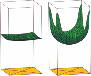
An illustrative example of the Concus-Finn criterion is that of water in a micro-beaker with a square base (fig. 5.19). If the contact angle with the walls is larger than 45°, the free surface has the curvature indicated in the left figure. When the contact angle is decreased below the Concus-Finn limit, filaments spread upward in the corners. Their extent is limited by their weight.
Figure 5.19 Free surface of water in a micro-beaker: filaments spread upwards when the contact angle is below the Concus-Finn limit of 45°. Left, contact angle 70°; right, contact angle 40°.
5.3.5 Extended Concus-Finn Relation
A generalization of the Concus-Finn relation has been proposed in [10] derived from the work of K. Brakke [4]. When the two planes do not have the same wettability (contact angles θ1 and θ2), the relation (5.15) becomes
(5.19) ![]()
Remember that α is the wedge half-angle. Usually microfluidic systems are etched in silicon, glass or plastic with a cover plate on top, glued or fixed by direct bonding. Hence the upper corners frequently have different contact angles with the liquid (fig. 5.19). An important consequence of relation (5.17) applies to trapezoidal microchannels (fig. 5.20).
Figure 5.20 Cross section of rectangular and trapezoidal microchannels.

When a glass cover is sealed on top of the system, the upper corners may form an angle of 45° and the extended Concus-Finn condition indicates the following limit
The glass cover may be quite hydrophilic, say θ1 ~ 60°, and if the channel is also hydrophilic, say θ2 ~ 70°, then (θ1 + θ2)/2 ~ 65° and the liquid spreads in the upper corners, leading to unwanted leakage.
The same generalization applies to the non-wetting case. The extended Brakke-Concus-Finn de-wetting condition for a corner is
(5.21) ![]()
Figure 5.20 shows two shapes of a droplet in a groove for two couples of contact angle: (θ1, θ2) = (45°, 60°) and (θ1, θ2) = (145°, 160°). In the first case, relation (5.17) is verified and the droplet spreads; in the second case, relation (5.18) is verified and the droplet detaches from the groove line.
5.3.6 Droplet in a Wetting/Non-wetting Corner
In this section, the behavior of a droplet in a 90° wedge is investigated, in the case where one side of the wedge is wetting and the other non-wetting. It is expected that, if the contact angle on the wetting side is small and that on the non-wetting side is large, the drop will be positioned on the wetting side. It is intuitive to think that this will happen if the difference between the non-wetting contact angle and the wetting contact angle is large. By referring to [4], a criterion for the drop to be positioned on the wetting side only is
(5.22) ![]()
α being the wedge half-angle. Relation (5.20) can be verified by numerical simulation as shown in figure 5.21.
Figure 5.21 Two shapes of droplet in a 90° wedge. Left, filament when (θ1, θ2) = (45°, 25°). Right, detachment when (θ1, θ2) = (140°, 160°).

The results of sections 5.3.4 and 5.3.5 can be shown on the same plot in a (θ1, θ2) coordinate system for a given groove angle α (fig. 5.22). Along the line θ1 = θ2, we have the Concus-Finn relations. The droplet spreads as a filament below the limit defined by θ1 + θ2 < π - 2α; the droplet detaches from the groove line above the limit defined by θ1 + θ2 > π + 2α. If θ1 - θ2 > π − 2α, the droplet migrates onto the θ1 plane, and in the opposite case, onto the θ2 plane. In the domain (θ1 + θ2 > π - 2α; θ1 + θ2 < π + 2α; |θ1 - θ2| < π - 2α) the droplet stays attached to the groove line.
Figure 5.22 Droplet in a corner with wetting and non-wetting sides, depending on the surface properties. Left: the droplet stays attached to the corner for contact angles 60°, 130°. Right: When the floor contact angle is reduced to 30°, the drop migrates entirely to the floor.
5.3.7 Discussion
In a general way, the surface tension does not appear in the Concus-Finn relations. Thus, these relations also apply for two-phase liquids, i.e. droplets of water in organic continuous phase, or droplets of organic liquid in an aqueous phase. Relation (5.15) shows that a droplet of oil surrounded by water is likely to form in hydrophilic channels, because the water spreads along the solid wall, and relation (5.16) shows the opposite for hydrophobic channels, i.e., oil spreads and a water droplet is formed. This is why flow focusing devices (FFDs), used to produce calibrated microdrops of aqueous phase in an organic media, must have their interior walls hydrophobic, a state usually obtained by silanization.
In microtechnology, wedges and corners often form a 90° angle, so that a droplet disappears in the form of filaments if the wetting angle on both planes is smaller than 45°. One must be wary that, when coating the interior of microsystems with a strongly wetting layer, in order to have a very hydrophilic (wetting) surface, droplets may disappear; they are transformed into filaments in the corners.
An interesting confirmation of the Concus-Finn relations has been done by Khare et al. in triangular shape wedges. They have shown that filament spreading can be triggered by the use of an electric field: it is known that electrowetting voltage reduces the contact angle and, once the contact angle is below the Concus-Finn limit, the droplet spreads along the groove line as a filament [11].
5.4 Conclusion
In this chapter the behavior of a microdrop located between two non-parallel plates has been investigated. In the case of tapered plates, a droplet is not, in general, at equilibrium. The generalized Hauksbee law governs the motion of the droplet, which is either towards the wedge line or away from it depending on the values of the contact angles of the liquid with each plate and the.
In the case of a droplet located very close to the groove line, the generalized Concus-Finn relations govern the equilibrium morphology of the droplet: depending on the liquid contact angles with the solid plates, it can spread along the groove line as a filament, detach from the groove line, migrate onto one of the two plates or stay attached to the groove line. Figures 5.23, 5.24, and 5.25 summarize the possibilities for a selection of wedge angles.
Figure 5.23 The different possible droplet location depending on the values of θ1 and θ2 (2α = 90°).

Figure 5.24 The different possible droplet location depending on the values of θ1 and θ2 (2α = 45°).

Figure 5.25 The different possible droplet location depending on the values of θ1 and θ2 (2α = 135°).

5.5 References
[1] F. Hauksbee, Philos. Trans. 27, p. 395, 1712.
[2] A.A. Darhuber, S.M. Troian, “Principles of microfluidic actuation by modulation of surface stresses,” Ann. Rev. Fluid Mech. 37, pp. 425–455, 2005.
[3] J. Berthier, K. Brakke, F. Grossi, L Sanchez, L. Di Cioccio, “Silicon die self-alignment on a wafer: stable and unstable modes,” Sensors and Transducers Journal 115(4), p. 135, 2010.
[4] K. Brakke, “Minimal surfaces, corners, and wires,” J. Geom. Anal. 2, pp. 11–36, 1992.
[5] C. Litterst, S. Eccarius, C. Hebling, R. Zengerle, P. Koltay, “Increasing μDMFC efficiency by passive CO2 bubble removal and discontinuous operation,” J. Micromech. Microeng. 16, pp. 248–253, 2006.
[6] N. Paust, C. Litterst, T. Metz, M. Eck, C. Ziegler, R. Zengerle, P. Koltay, “Capillary-driven pumping for passive degassing and fuel supply in direct fuel cells,” Microfluid. Nanofluid. 7, pp. 531–543, 2009.
[7] H. Bouasse. Capillarité et Phénomènes Superficiels. Librairie Delagrave, Paris, 1924.
[8] P. Renvoisé, J. W. M. Bush, M. Prakash and D. Quèrè, “Drop propulsion in tapered tubes,” EPL 86, p. 64003, 2009.
[9] P. Concus, R. Finn, “On the behavior of a capillary surface in a wedge,” PNAS 63(2), pp. 292–299, 1969.
[10] J. Berthier. Microdrops and Digital Microfluidics. William-Andrew Publishing, 2008.
[11] K. Khare, M. Brinkmann, B.M. Law, S. Herminghaus, and R. Seemann, “Switching wetting morphologies in triangular grooves,” Eur. Phys. J. Special Topics 166, pp. 151–154, 2009.