Chapter 10
Digital Microfluidics
10.1 Abstract
From its beginning, digital microfluidics has been developed for biotechnological applications, with the aim to manipulate extremely small volumes of sample liquid. Volumes smaller than 60 nl can be manipulated in such microsystems and used to transport biologic targets. In parallel, digital microfluidics has seen many applications in the field of optofluidics, such as tunable lenses and electronic display screens.
Digital microfluidics consists of moving, merging, separating, and mixing droplets on a locally planar surface. The actuation force can be of two types: electric or acoustic. In the first case, the droplets are moved on a substrate paved with electrodes; this technique is called electrowetting. In the second case, droplets are actuated by acoustic surface waves (SAW) directionally guided. Although some interesting applications have been developed using acoustic methods [1–3], we will only present here electrowetting, and its practical form called “electrowetting on dielectric” (EWOD). The theory of electrowetting is presented first, then the different mechanisms for droplet manipulation are analyzed, and finally some applications in the fields of biotechnology and optofluidics are given.
10.2 Electrowetting and EWOD
In this section, we present the Berge-Lippmann-Young law, which is the basis for the practical developments of digital microfluidics, and we investigate the potentialities of EWOD by analyzing its physical limits.
10.2.1 Berge-Lippmann-Young Equation (BLY)
The principle of electrowetting derives from the Berge-Lippmann-Young (BLY) equation [4,5]. The first historical relation derived by Lippmann stated that the apparent contact surface tension of an electrically conducting liquid in contact with a solid is modified by an electric field. This apparent change is attributed to the double layer that forms on the substrate surface. Using Gibbs’ interfacial thermodynamics [6],
where V is the electric potential, ![]() the effective or apparent surface tension and qSL the field-induced surface charge density in counter-ions. More recently, Berge has shown that the Lippmann relation results in a change of the apparent contact angle. The Berge-Lippmann-Young (BLY) equation describes the change of contact angle with the applied voltage,
the effective or apparent surface tension and qSL the field-induced surface charge density in counter-ions. More recently, Berge has shown that the Lippmann relation results in a change of the apparent contact angle. The Berge-Lippmann-Young (BLY) equation describes the change of contact angle with the applied voltage,
where θ, θ0 are the actuated and Young contact angles, C the capacitance of the substrate, γLG the liquid-air surface tension, and V the electric potential. According to equation (10.2), the contact angle decreases when an electric field is applied (fig. 10.1).
Figure 10.1 Effect of an electric field on a conducting droplet: the contact angle θ decreases with the applied electric potential.

In fact, the BLY equation recovers only a part of the physics of electrowetting. In reality, the interface is locally deformed by the electric forces associated to the Maxwell tensor [7]. An electromechanical approach has been developed by Jones et al. [8,9], Kang [10], and recently reviewed by Zeng and Korsmeyer [11]. In the case of liquids, the body force density due to an electric field is given by the Korteweg-Helmholtz relation
where ρ is the mass density of the liquid, εf the permittivity of the liquid, and σf the electric charge density. The first term on the right side of (10.3) corresponds to the electrostatic force; the second term to the dielectrophoretic force. The last term describes electrostriction and can be neglected here as the mass density of the liquid remains constant. The force acting on a volume element δV is obtained by integrating equation (10.3). It can be shown that it is equivalent to integrating the momentum flux density, i.e., the Maxwell stress tensor
along the boundaries of the volume ΔV. In (10.4), the notation E2 corresponds to ![]() and δik is the Kronecker delta function: δik = 0 if i ≠ k and δii = 1 if i = k; and i, k = x, y, z. Surface integration of (10.4) is much easier than volume integration of (10.3). The net force acting on the liquid volume element is
and δik is the Kronecker delta function: δik = 0 if i ≠ k and δii = 1 if i = k; and i, k = x, y, z. Surface integration of (10.4) is much easier than volume integration of (10.3). The net force acting on the liquid volume element is
where the Einstein summation convention – summation on the repeated indices – has been used. At the surface of a perfectly conducting liquid, on the gas side, the electric field is perpendicular to the surface (figure 10.2), and related to the surface density of electric charge σs by Gauss’ law:
(10.6) ![]()
Figure 10.2 Electric force acting at the interface of a conducting liquid.

where ![]() is the outward unit normal vector. Note that the electric field vanishes in the conducting liquid. If we consider the x, y, z axis system such that the x-axis is aligned with
is the outward unit normal vector. Note that the electric field vanishes in the conducting liquid. If we consider the x, y, z axis system such that the x-axis is aligned with ![]() , then the electric field is
, then the electric field is ![]() = (Ex, 0, 0) in the gas domain and
= (Ex, 0, 0) in the gas domain and ![]() = (0, 0, 0) in the liquid domain. In the gas domain, the Maxwell tensor is
= (0, 0, 0) in the liquid domain. In the gas domain, the Maxwell tensor is
(10.7) 
and vanishes in the liquid domain,
(10.8) ![]()
We can now integrate (10.5); the cross terms xy, yz, and zx are all zero, the forces in the y (respectively z) direction cancel out, and we find that the only non-vanishing contribution is a force directed along the outward normal ![]() :
:
where δA is an elementary surface area of the interface. In (10.9), Pe is the electrostatic pressure defined by ![]() . The electrostatic pressure Pe acts on the liquid surface, and brings a negative contribution to the total pressure within the liquid. The liquid interface is distorted by the electric forces acting on it. The distortion depends on the distribution of charges σf at the surface. In the case of electrowetting, the electric charges at the liquid-gas interface are located close to the triple contact line, as sketched in figure 10.3, within a distance equal to the dielectric thickness d.
. The electrostatic pressure Pe acts on the liquid surface, and brings a negative contribution to the total pressure within the liquid. The liquid interface is distorted by the electric forces acting on it. The distortion depends on the distribution of charges σf at the surface. In the case of electrowetting, the electric charges at the liquid-gas interface are located close to the triple contact line, as sketched in figure 10.3, within a distance equal to the dielectric thickness d.
Figure 10.3 Schematic of the electric charge distribution in the vicinity of the triple contact line. Electric charges are located at the solid-liquid interface and at the liquid-gas interface, approximately within a distance d from the solid surface. In reality, this is a very simplified view since the liquid interface is distorted by the electric forces very close to the triple contact line.

The problem of the surface distortion has been solved by Kang [10] and Vallet et al. [12] using the Schwarz-Christoffel conformal mapping, assuming that the shape of the interface at the contact of the solid substrate is a wedge [13]. The electric potential Φ satisfies the Laplace equation ∇2Φ = 0 and consequently is a harmonic function. The theory of analytic and harmonic functions states that there exists a conformal mapping (the Schwarz-Christoffel mapping) that transforms the fields ![]() and Φ for a half plane into the same fields for a wedge (figure 10.4).
and Φ for a half plane into the same fields for a wedge (figure 10.4).
Figure 10.4 Principle of the Schwarz-Christoffel conformal mapping. The two fields ![]() and Φ are transformed from a simple half plane geometry (with an evident solution) to the geometry of a wedge. Note the concentration of the electric field around the tip of the wedge.
and Φ are transformed from a simple half plane geometry (with an evident solution) to the geometry of a wedge. Note the concentration of the electric field around the tip of the wedge.

This mapping shows that the field and charges concentrate at the tip of the wedge. In fact, as for any harmonic function near a geometric singularity, the electric field is singular at a wedge (see for example Thamida and Chang [14]), but the Maxwell pressure is integrable and produces a finite Maxwell force at the contact line after (10.5) is integrated:
Note that the electric forces distribution on the liquid-gas interface due to the Maxwell stress is limited to a very small region close to the triple line. Note also that using (10.10) and making a balance of the forces – electric plus capillary – in the horizontal direction on the triple line results in the BLY equation.
The electromechanical approach shows that the BLY equation comes directly from the Maxwell stress on the liquid-gas interface near the contact line. In fact, since the liquid has a much higher permittivity (and conductivity) than the gas, it is the wedge shape of the gas phase that is responsible for distortion of the contact angle, as is clearly shown by the Schwarz-Christoffel transformation. A consequence of equation (10.11) is that there is a vertical force on the liquid interface near the triple line. This vertical force increases quickly when the contact angle decreases. This could be an explanation for the phenomenon of contact angle saturation (the contact angle cannot go to zero), usually accompanied by ejection of nanodrops.
The wedge theory presented above is only a simplistic approximation of the reality. In fact, extremely close to the solid surface, the shape of the interface is complex. It has been shown that the real contact angle is still the Young contact angle, but within the width of the electrical double layer, the interface is deformed by electric forces, and the apparent contact angle is the BLY contact angle, as shown in figure 10.5 [8,9].
Figure 10.5 Close up view of the three-phase contact at the wall.

10.2.2 Electrowetting Force
In chapters 1 and 6 we have seen that the capillary line force density on a triple line is
Using the electro-capillary equivalence, and the BLY law, we find
The difference of contact angles between the “hydrophilic” part of the triple line and the “hydrophobic” part results in a net capillary force. Let us sketch a droplet placed on EWOD electrodes in the drawing of figure 10.6. The electro-capillary force acting on the droplet is readily deduced from (10.13)
Figure 10.6 Sketch of the contact of a drop with the substrate (we have sketched the usual situation where the contact angle on the non-actuated electrode (left) is larger than 90°, and that with the actuated electrode (right) is smaller than 90°).

From (10.12), the capillary force in the direction x (unit vector ![]() ) on the hydrophilic electrode is given by
) on the hydrophilic electrode is given by
(10.14) ![]()
![]() being the unit vector normal to the surface, and dl a unit element of the contour line. Equation (10.13) can be integrated to [3]
being the unit vector normal to the surface, and dl a unit element of the contour line. Equation (10.13) can be integrated to [3]
(10.15) ![]()
where e is the width of the electrode. Note that the real shape of the triple line has no importance. Figure 10.7 shows different forms of experimental contact lines. Noting that the x-direction force on the triple line outside the electrodes vanishes, it is concluded that the x-direction capillary force on the droplet, whatever its shape, is
Figure 10.7 Different shapes of droplets on EWOD electrodes: left, water droplet; right, ionic liquid droplet.
(photo courtesy Ph. Clementz).

(10.16) ![]()
10.2.3 Limitations of EWOD – Saturation, Dielectric Breakdown and Hysteresis
There are three limitations of EWOD: (1) the saturation effect, (2) dielectric breakdown, and (3) hysteresis.
10.2.3.1 Saturation Limit
If the electric potential is increased, equation (10.2) predicts a zero contact angle for some value of the electric potential. In fact, above a certain value of the potential, the apparent contact angle does not decrease anymore. It is the saturation effect. Different explanations have been proposed for this effect [3,15–17]. It is very convenient, although approximate, to use the zero surface-liquid energy limit model pioneered by Ralston et al. [16,17]. We shall refer to this model by the abbreviation PQRS. In this approach, the effective solid-liquid surface tension decreases with the voltage according to equation
and the voltage-dependant Young’s law can be cast in the form
The effect of relation (10.18) is sketched in figure 10.8 for different values of the applied voltage. For a zero voltage, the force balance is that defined by the classical Young’s law. As the voltage increases, the effective solid-liquid surface tension decreases, and the contact angle decreases according to the BLY equation. The lower limit for the effective solid-liquid effective surface tension is zero; when this value is reached, the minimum contact angle is obtained. This minimum value is the saturation contact angle θsat.
Figure 10.8 Sketch of the different contact angles depending on the applied voltage. Left: at zero potential, the contact angle is determined by the classical Young law; middle: the contact angle decreases when the applied voltage increases; right: the lower limit of the contact angle is obtained when the solid-liquid surface tension vanishes.

According to equation (10.18), at saturation ![]() = 0 and
= 0 and
(10.19) ![]()
Using equation (10.17) and Young’s law, the saturation potential is
(10.20) ![]()
In order to take into account the saturation effect, Berthier has proposed using a modified BLY law [18]
where La is Langevin’s function La = coth(3X) − ![]() , and θS is the saturation angle. The Langevin law is well adapted to such a situation because it closely follows the quadratic law for small voltage and has an asymptotic behavior at large voltages. Below the saturation limit, equation (10.21) reduces to the usual BLY law. A comparison between experimental results and (10.21) is shown in figure 10.9.
, and θS is the saturation angle. The Langevin law is well adapted to such a situation because it closely follows the quadratic law for small voltage and has an asymptotic behavior at large voltages. Below the saturation limit, equation (10.21) reduces to the usual BLY law. A comparison between experimental results and (10.21) is shown in figure 10.9.
Figure 10.9 Modified BLY law using Langevin’s function: comparison with experiments (continuous lines correspond to the Langevin function and dots to the experimental values).

10.2.3.2 Dielectric Breakdown
EWOD electrodes are coated with a thin dielectric layer in order to avoid electrolysis of the conducting fluid. Above this dielectric layer, a very thin hydrophobic layer is usually deposited to enhance the electrowetting effect by increasing the value of θ0 above 90° (fig. 10.10).
Figure 10.10 Schematic cross section of an EWOD digital element.

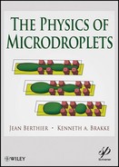
When the electric field is larger than a threshold – called the critical electric field, denoted EBD – the dielectric is disrupted, i.e. cracks suddenly form and the dielectric integrity is lost (fig. 10.11). This threshold is also called the theoretical dielectric strength of the material. It is an intrinsic property of the bulk material. The detailed physical explanation of dielectric breakdown is not the subject of this chapter and is well documented in the literature [19,20]. For a dielectric of thickness d, the critical electric field EBD is related to the dielectric breakdown voltage VBD by
Figure 10.11 (a) Dielectric breakdown at the vicinity of a spherical object; the breakdown is materialized by the formation of cracks having the shape of tree branches (photo CEA-Leti); (b) close-up on the “tree effect”; (c) electrostatic breakdown model showing the growth of “failure tree” due to electron avalanche.
Reprinted with permission from [54]; ©IOP 2003.
(10.22) ![]()
Indications of the value of the critical electric field are given in table 10.1 for some common materials. In the preceding section, we have developed the notion of saturation potential. Typically, saturation potentials are of the order of 80 V for a substrate of capacitance C ≈ 2.210−5 F/m2, obtained with a total dielectric/insulating layer of 1.5 μm thickness approximately. Thus the electric field at saturation is of the order of 55 V/μm. Note that this value is just below the breakdown value of Teflon. In other words, chips are usually designed to function at the saturation potential.
Table 10.1 Values of the breakdown voltage for some common materials (units V/μm. Note that the values indicated here are given for perfect and ideal materials. Real values are usually less than these.
![]()
However, dielectric breakdown is sometimes observed at lower values of the potential. Breakdown frequently occurs when there are defects in the substrate surface or when objects such as cells or proteins adhere to the substrate. A possible explanation could be the anomalous value of the electric field in the vicinity of geometrical inhomogeneities. The contact of an object with the substrate is sketched in figure 10.12. Assuming that the liquid is perfectly conductive and that the object is insulating or at least its envelope is insulating, and if ε1 and εd denote the relative permittivity of the object and the solid dielectric respectively, the electric potential is given by the Laplacian equation
Figure 10.12 Electric scheme of the contact of an object with the substrate.

(10.23) ![]()
From a theoretical point of view, the electric potential can be obtained through the Schwarz-Christoffel conformal mapping. If the angle is sharp, there is a pole of the transform at the tip of the wedge (fig. 10.13). This anomalous, localized value of the electric field may increase the voltage above the dielectric breakdown voltage [3]. This could be the explanation why dielectric breakdown is sometimes observed when cells or proteins adhere to the substrate, or when the surface get crackled after a long period of use. Work is currently under way to reinforce the level of the dielectric breakdown voltage: without raising the value of the capacitance.
Figure 10.13 Contour plot of the magnitude of the electric field below a cell sticking to the surface (Comsol software).

10.2.3.3 Hysteresis
As a general rule, advancing and receding contact angles are different. This is due to the roughness of the substrate, and the difference exists even for apparently smooth surfaces. Electrowetting is not an exception; the contact angle is not the same when the potential is gradually increased or gradually decreased (fig. 10.14). The contact angle difference between advancing and receding contact angles can be approximated by a constant angle a. This hysteresis angle depends on the quality of the substrate and is reduced for superhydrophobic substrates. It is usually in the range 1° – 30°. Besides the contact angle difference, it is observed that a droplet of conductive liquid does not move from one electrode to the next as soon as an electric actuation is applied. A minimum voltage is required to have the triple line moving. It has been shown that the minimum voltage required to obtain interface motion is linked to the hysteresis contact angle a [3,21]:
Figure 10.14 Hysteresis of electrowetting phenomenon and advancing and receding apparent contact angle. Insert: experimental observation of hysteresis (substrate SiOC with very low hysteresis level).

(10.24) ![]()
10.2.3.4 Minimum and Maximum Actuation Voltages – Working Range
Taking into account saturation limit, dielectric breakdown and hysteresis, an approximate working range can be determined [21]. On one hand, a minimum actuation voltage based on hysteresis has been derived, on the other hand a maximum voltage linked to saturation and dielectric breakdown has been found. Hence, the domain for EWOD workability is then given by the following relation:
At this stage, we remark that the interval [Vmin, Vmax] depends on the capacitance C. Microdevices with thinner layers of dielectric have a larger capacitance and require lower level of actuation. There is a clear advantage in trying to increase the specific conductance of the dielectric layer: the electric potentials needed to actuate the droplets will then be lower. Equation (10.25) can be translated in terms of line force by
(10.26) ![]()
showing the range of electrowetting force. Using a typical value for the specific capacitance C ≈ 0.03 mF/m2, relation (10.25) shows that the minimum electro-capillary forces lies in the range 1–20 μN, and the maximum forces in the range 15–40 μN.
10.3 Droplet Manipulation with EWOD
In order to be effective, a droplet microfluidic technique should handle some basic operations. These operations are: droplet motion, division and merging, and dispensing. In the following sections we investigate how these operations are performed on EWOD systems and we show that a special design, called “covered” EWOD – as opposed to “open” EWOD systems, facilitates these operations. Indeed, while droplet motion is possible on both open and covered EWOD systems, the other operations require the covered EWOD geometry. First let us present typical architectures of “open” and “covered” EWOD systems.
10.3.1 Open vs. Covered EWOD System
In an “open” EWOD system, droplets are just deposited on the substrate, which is paved with electrodes, and isolated by a dielectric microlayer, covered by a hydrophobic coating (fig. 10.15).
Figure 10.15 Photo of an “open” EWOD microsytem. The grounded electrodes are the catena wires running parallel to the chip.
(Courtesy Y. Fouillet, CEA-Leti).

Covered EWOD systems are just open EWOD system with a cover plate. In such systems, the substrate which supports the droplet is similar to that of open EWOD systems described previously. But, in this case, a top plate covers the droplet [22,23]. This top plate consists of an electrode usually made of ITO (Indium-Tin oxide) coated with a thin layer of Teflon. Thus, without electric actuation, the contact is hydrophobic with both plates, as shown in fig. 10.16.
Figure 10.16 Schematic view of a covered EWOD microsystem; Left: droplet squished between two plates. Right: covered EWOD microsystem fabricated by the LETI (photo CEA-LETI).

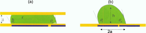
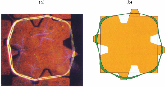
In a covered EWOD system, the droplet follows closely the shape of the electrodes (fig. 10.17). In such a configuration, the vertical gap is very small compared to the horizontal dimension of the droplet, and the surface area of the free interface (liquid-air) is very small compared to that of the solid-liquid interface. Consequently, the energy of the liquid-air interface is much smaller than that of the solid-liquid interface and the droplet adopts the shape of the underlying electrode. This is why a droplet is nearly square when the electrodes are square.
Figure 10.17 Left: photograph of a “square” droplet in a covered EWOD microchip; right: the droplet simulated with the Surface Evolver).

10.3.2 Droplet Motion
Because the friction on the substrate is quite small (even when a cover plate is present), the electrowetting force is usually sufficient to move a liquid droplet. Water, water with surfactants, and biologic fluids can be moved by EWOD. Using the capillary equivalence, it is comparable to the motion of a droplet under a gradient of wettability [24, 25]. Figure 10.18 shows the Evolver simulated motion of the droplet. Note that Evolver does not include the dynamic and viscous forces; hence it can only indicate if the motion occurs. However, because the surface tension forces are usually dominant – as soon as the surface tension is sufficiently important – there is a similarity between the real motion and the simulated motion. Estimates of the Weber, Capillary and Ohnesorge non-dimensional numbers assess that the surface tension forces are dominant [26]. The Weber number is the ratio of the inertial and surface tension forces,
Figure 10.18 View of a droplet of ionic liquid moving to the left from a hydrophobic substrate to a hydrophilic substrate (Surface Evolver). Note that the “hydrophilic” forces applied on the front part of the triple line and the “hydrophobic” forces applies on the rear part of the triple line contribute together to the motion. This is why a hydrophobic substrate is preferred in EWOD devices.

(10.27) ![]()
where V is the liquid velocity, ρ the liquid density, and R the droplet radius. Usually for EWOD microsystems the Weber number is smaller than 0.01. On the other hand, the ratio of the viscous and the surface tension forces is given by the Capillary number,
(10.28) ![]()
where η is the liquid viscosity. Usually also the Capillary number is less than 0.01. This is equally the case for the Ohnesorge number,
(10.29) ![]()
where Re is the Reynolds number. It is concluded that the surface tension forces are dominant during droplet motion.
Let us analyze the forces on a droplet located on the boundary between an actuated (ON) and non-actuated (OFF) electrode. The line force is fa = γcos θa on the actuated side and f0 = γcos θ0 on the non-actuated side. The resulting electrowetting force is
(10.30) ![]()
where e is the length of the junction between the electrodes. Because cos θ0 is usually negative, two terms on the right side of the preceding equation add together.
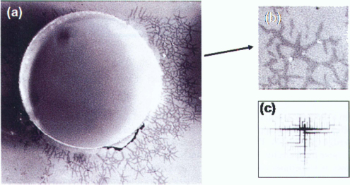
In figure 10.19, it is shown that the calculated motion is very similar to the real motion.
Figure 10.19 (a) Side view of a moving droplet (ionic liquid); (b) Evolver simulation of the same droplet; (c) photograph of a water droplet during its motion; (d) end of motion (courtesy CEA/LETI). One sees quite well the asymmetric shape of the droplet during its motion.
10.3.3 Moving Droplet Velocity
In digital microfluidic systems, a droplet moves from one location on the chip to the next incrementally. Because inertia forces are small, the droplet accelerates very quickly, reaches a nearly steady velocity, and stops abruptly. In this section we focus on the “nearly steady state” velocity of the droplet.
Velocity depends on the strength of the electro-capillary forces. It is then expected that velocity of the droplet is directly related to this force. In reality, the motion of micro-drops is a complex physical phenomenon involving surface tension, viscosity, dynamic contact angles, internal motion, etc., and is still a subject of research. In the following section, we present a very simple model proposed by Chen et al. [27] to make an estimate of the velocity of micro-drops during their motion in EWOD microsystems.
10.3.3.1 Model
We consider a droplet of volume Vol either sandwiched between two plates (covered EWOD) or sitting on a flat surface (open EWOD), as sketched in figure 10.20.
Figure 10.20 (a) Droplet moving in a covered EWOD configuration. (b) Droplet moving in an open EWOD configuration.
The following simplified analysis can be done: if the velocity of motion is constant, the electrowetting force balances the friction force due to viscous dissipation at portions of the substrate in contact with the drop, assuming that the other resisting forces, such as contact-line resistance, are negligible compared to the viscous dissipation. Then, in the case of the covered system, the contact surface is assumed circular (which is not true in reality),
where vcov is the global velocity and τw is the substrate friction, approximated with the Poiseuille profile
(10.32) ![]()
Using the capillary equivalence, we can express the electrowetting force by
and by equating equations (10.31) and (10.33), we deduce the droplet velocity of motion,
(10.34) ![]()
If the voltage is smaller than the saturation voltage, we can use the Lippmann-Young relation, and the velocity can be estimated by
Equation (10.35) shows that the velocity of motion is proportional to the square of the electric potential.
Similarly, in the case of the open EWOD system,
(10.36) ![]()
The shear stress τw can be approximately expressed by
(10.37) ![]()
based on an approximate peak velocity located at 2/5 of the drop height, according to numerical simulations. Then
On the other hand, the electrowetting force is
and the droplet velocity is obtained by combining equations (10.38) and (10.39):
(10.40) ![]()
In terms of voltage (far from the saturation limit), we have
(10.41) ![]()
It is easy to see that the velocity of a droplet is larger in an open EWOD system by forming the ratio vcov/vopen:
In (10.42), the term a/h is of the order of 1, and δ ![]() r, showing that the velocity of motion is much larger in an open configuration. We note that this model assumes that the two dominant forces are the electrowetting and the friction forces, and supposes an established Poiseuille flow inside the droplet. It neglects internal recirculation, the effect of the triple line, the deformation of the droplet during motion, etc. Much is still to be done to understand the motion of droplets under electrowetting actuation. Lets us mention that the first numerical simulations of Dolatabati et al. [28] agree on some points with Chen’s model, but disagree about the effect of the vertical gap δ. However, it is a general observation, according to equations (10.35) and (10.42), that the velocity of motion is proportional to the electrowetting force and inversely proportional to the viscosity.
r, showing that the velocity of motion is much larger in an open configuration. We note that this model assumes that the two dominant forces are the electrowetting and the friction forces, and supposes an established Poiseuille flow inside the droplet. It neglects internal recirculation, the effect of the triple line, the deformation of the droplet during motion, etc. Much is still to be done to understand the motion of droplets under electrowetting actuation. Lets us mention that the first numerical simulations of Dolatabati et al. [28] agree on some points with Chen’s model, but disagree about the effect of the vertical gap δ. However, it is a general observation, according to equations (10.35) and (10.42), that the velocity of motion is proportional to the electrowetting force and inversely proportional to the viscosity.
10.3.3.2 Experimental Results
The variation of the velocity with the square of the voltage predicted by the preceding model has been checked by Pollack et al. [29] for low to moderate values of the applied voltage. There is a very interesting point in Pollack’s publication: the velocity is the same when the dimensions are reduced homothetically, i.e., when the ratio δ/r is kept constant. This is exactly what is predicted by equations (10.35) and (10.42).
At large voltages, the electrowetting force saturates and in consequence the velocity of motion is limited by an asymptote (fig. 10.21).
Using the modified Lippmann law based on the Langevin function, equation (10.35) can be recast in the form
(10.43) ![]()
and equation (10.42) in the form
(10.44) ![]()
where La is the Langevin function, and θs the saturation angle. These relations between the droplet velocity and the voltage then have the shape shown in figure 10.21. There is an asymptote at high voltages that represents the upper bound of the velocity. In conclusion, velocity of motion in electrowetting devices is limited by the saturation of the electrowetting force and very high velocities cannot be expected. This upper limit on drop velocity is typically 15 cm/s.
Figure 10.21 Schematic relation between the velocity of motion and the voltage, showing saturation for large actuation potentials.

Experimental observations confirm that the droplet velocity decreases when the viscosity of the liquid increases (fig. 10.22). One expects that there is a viscous limit above which liquids cannot be moved in EWOD microsystems. In biology, viscous (even non-Newtonian) liquids are sometimes used, like polysaccharides, blood, or alginates. Their viscosity increases with the concentration of monomers, dimers, trimers, etc. [30]. For instance, in chemical applications, it has been observed that ionic liquids can be displaced on EWOD chips, but at a small velocity (bottom curve of figure 10.22).
Figure 10.22 Droplet velocity is decreased by increasing the viscosity of the liquid.

Let us finally analyze the effect of surfactants. Remember that in biology and biotechnology, surfactants are currently used for many reasons, the most important being to disperse aggregates and to reduce adhesion on the solid walls. A comparison of the droplet velocity between deionized water and biologic buffer is shown in figure 10.23. We observe that hysteretic effects are reduced when surfactants are present in the solution, but the droplet motion is much slower. The reduction of the hysteresis there should be in the case of biologic buffers can be attributed to the reduction of the quantity γLG sin θ0 (from equation 10.25), and the reduction of the velocity is due to a smaller value of the solid-liquid surface tension θSL (from equations 10.33 and 10.39).
Figure 10.23 Observed velocities of a droplet as a function of applied voltage: velocities are higher when the surface tension is large, except at very low voltage.

10.3.4 Droplet Merging and Division
The merging of two droplets is straightforward. It suffices to move two droplets from opposite sides onto the same electrode. However, the division of one droplet into two is much more complicated. The principle of division is shown in figure 10.24. The droplet is stretched by the electrowetting forces along the electrode line, and pinched on the hydrophobic non-actuated electrode. The surface tension force of the free surface opposes these forces. The balance of these forces determines if the droplet can be split in two.
Figure 10.24 Principle of droplet division: division is obtained by a pinching in the central area and a stretching from the two ends.

Numerical investigations with Surface Evolver show that the division of a water droplet is not possible in open EWOD systems, but only in covered EWOD system, if the vertical distance between the two plates is not too large [31]. In the open EWOD system the pinching and stretching forces are not sufficient to dominate the surface tension forces and the droplet escapes laterally from the pinching region, randomly on one side or the other (fig. 10.25). This can be viewed as an example of the double-bubble instability described in Chapter 2.
Figure 10.25 (a) at the start of the actuation, a pinching occurs in the middle of the water droplet; (b) droplet escapes randomly on one side.

This is not the case of covered systems, where the droplet can be efficiently separated in two equal daughter droplets – if the vertical distance is not too large. Let us define a characteristic dimension R representing the droplet volume Vol by
(10.45) ![]()
where δ is the vertical distance between the plates, and define the scaling number λ by
(10.46) ![]()
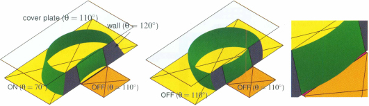
It is numerically shown that if λ is sufficiently small, the droplet can be cut into two daughter droplets (fig. 10.26). The critical value of λ depends on the actuated/non-actuated contact angles and the surface tension. The key is that the splitting must happen faster than the droplet can respond to the double-bubble instability.
Figure 10.26 Division of a droplet is possible in a covered EWOD device if the ratio of the vertical gap and a characteristic dimension of the droplet (representing its volume) is small enough (the liquid is water, and the contact angles are 80°, 120° and 110° respectively for the actuated, non-actuated electrodes and cover plate).

Let us investigate further the question of droplet splitting. Let us place ourselves in a more general case and ask the question: can a droplet placed between two horizontal parallel planes be cut into two daughter droplets by capillary means?
10.3.4.1 Droplet Stretching
The first idea that comes to mind is to stretch the droplet by capillary forces, in order to elongate a filament that will eventually break. Then the question is reduced to: can a droplet be cut by exerting capillary traction forces on two ends?
Let us start with the artificial situation where a partial splitting has already occurred, in order to facilitate the splitting. The droplet is then supposed divided in two regions linked by a large thread (Fig. 10.27). Because the liquid wets the two substrates (bottom and top plates), capillary forces are exerting traction on the wetted perimeter of the droplet, as sketched in figure 10.28.
Figure 10.27 Sketch of a droplet placed between wetting walls, “artificially” stretched in two regions. The cover plane has been dematerialized for visualization.

Figure 10.28 Schematic of the initial droplet.

Let us follow first a theoretical approach which makes use of the free energy: The total surface energy is
where L denotes the liquid, G the gas and S the solid. Let us make the approximation that the free interfaces are flat. We have with the notations of figure 10.28 that
and
Moreover, the liquid volume is
If there is no evaporation, (10.48) implies that
(10.51) ![]()
Then, using (10.47)
(10.52) ![]()
Using (10.49), and remarking that L is constant, we find
(10.53) ![]()
and
The droplet evolves to find its minimum energy morphology. Relation (10.54) indicates that the liquid filament cannot shrink – i.e. R cannot increase – because an increase of R would increase the energy. Hence, the droplet cutting is; not possible by exerting capillary forces on the two ends.
We have checked this analysis numerically with Surface Evolver. The starting point is a droplet split in two circular regions, and linked by a thread (fig. 10.29). Using many different values of the parameters h, L, w, and R, cutting was never obtained.
Figure 10.29 Splitting cannot be obtained by varying the different parameters: (a) small L; (b) longer L; (c) small h; (d) small w.

10.3.4.2 Stretching and Pinching
Stretching the droplet is not sufficient to achieve splitting. Let us consider now an additional capillary force which is the pinching of the droplet. The question is then: can a droplet be cut by exerting capillary traction forces on two ends and a pinching in the middle? Figure 10.30 represents a droplet placed between two horizontal planes, with two hydrophilic (lyophilic) regions at both ends and a hydrophobic (lyophobic) region in the middle. In EWOD systems, such an action is obtained by actuating the two end electrodes and not actuating the middle electrode.
Figure 10.30 Simulation of a droplet pinched in the middle and stretched by the two ends. The cover plane has been dematerialized for visualization. Note that the cover plate is neutral (θ = 90°), hence only the capillary forces on the bottom plate contribute to the splitting.

The sketch of the capillary forces is shown in figure 10.31. The hydrophilic regions tend to stretch the droplet while the hydrophobic region pinches the middle of the droplet.
Figure 10.31 Schematic view of the droplet with the pinching in the thread region.

Let us follow a theoretical approach based on the free energy minimization. The total surface energy is
using the same notations as above, and where the indices 1 and 2 denote respectively the pinched and rounded regions of the liquid. In the case of EWOD, the actuated solid-liquid surface tension is ![]() . Let us make the approximation that the free interfaces are flat. We have, with the notations of figure 10.31
. Let us make the approximation that the free interfaces are flat. We have, with the notations of figure 10.31
(10.56) ![]()
and
(10.57) ![]()
On the other hand, the liquid-gas surface area is
(10.58) ![]()
The liquid volume is
If there is no evaporation, (10.59) implies that
Differentiating (10.55) yields
(10.61) ![]()
Using (10.60), we find
(10.62) ![]()
and noting that L is constant, but w and R vary,
(10.63) ![]()
Finally
The comparison to (10.54) shows that there is now an additional term on the right hand side of (10.64). This time, the sign of dE/dR can be positive or negative depending on the values of the parameters. In order to have splitting, the free energy E must decrease when the radius R increases: dE/dR < 0. The condition for splitting is then
Lipmann’s law states that electrowetting changes the value of the solid-liquid surface tension γS2L = ![]() (equation 10.1). Using the capillary equivalence for electrowetting, with regions 2 actuated and region 1 not actuated,
(equation 10.1). Using the capillary equivalence for electrowetting, with regions 2 actuated and region 1 not actuated,
(10.66) ![]()
(10.67) ![]()
By difference, and using the equality γS1G = γS2G, we obtain
(10.68) ![]()
Substitution in the Berge-Lippmann-Young (BLY) equation yields the relation
(10.69) ![]()
where C is the specific capacitance, and V the tension. Substituting back in (10.65) yields
where ξ is the electrowetting number. Relation (10.70) shows that splitting can be achieved if the vertical gap is sufficiently small and/or the electrowetting number sufficiently high, and/or the radius R sufficiently large. The radius R being approximately of the order of the electrode dimension, EWOD systems with small vertical gaps and/or large electrodes require a smaller voltage to cut the droplet. The fact that a high value of the electrowetting number facilitates the cutting is obvious: the more the droplet is stretched at both ends while it remains pinched in the middle, the easier is the cutting.
Note that relation (10.70) can be rewritten as
(10.71) ![]()
showing that the electrowetting number – in our case the voltage – can be progressively relaxed as R increases during the splitting. In other words, once the thinning of the liquid junction has started, the splitting is inevitable and goes to its end.
The numerical analysis confirms this theoretical approach (Fig. 10.32). A droplet can be cut in two if the vertical gap between the two plates is sufficiently small. When the vertical gap h is large, no shrinking in the middle of the droplet can be achieved.
Figure 10.32 Splitting is achieved when h is small (a), but not when h is sufficiently large (b).

10.3.5 Droplet Dispensing
Dispensing denotes the operation consisting of extracting liquid from a reservoir in order to form “digital” droplets. Let us analyze first dispensing in an open EWOD configuration.
10.3.5.1 Open EWOD
It is intuitive that if the width of the door – i.e. the opening in the vertical wall – is small compared to the volume of liquid in the reservoir, it will be impossible to extract a droplet through the door. Let us first characterize the volume of the droplet by the length scale R defined by
(10.72) ![]()
where Vol is the volume of the liquid in the reservoir, and let us define the scaling number λ as
(10.73) ![]()
where δ is the width of the door. Numerical calculation shows that when λ < 1.05 it is impossible to dispense any droplet from the reservoir (fig. 10.33). Hence open EWOD systems cannot be used for dispensing because the ratio λ is much smaller than 1 (when the reservoir is filled).
Figure 10.33 Numerical simulation of dispensing water droplets in an open EWOD geometry: dispensing is impossible when the volume of water in the reservoir is too large compared to the width of the “door”. The contact angles are 120° in the reservoir, 120° with the Ordyl wall and 60° on the actuated working electrode.

The threshold limit λ = 1 slightly depends on the liquid. Ionic liquid with a surface tension of 30 mN/m and an actuated contact angle of 50° can be dispensed for λ > 0.95. We reach the same conclusion: open EWOD systems cannot dispense droplets.
10.3.5.2 Covered EWOD
An experimental view of droplet dispensing in a covered EWOD system is shown in figure 10.34. First, a liquid tongue is pulled out of the reservoir on the electrode line by actuating the electrodes (1,2,3 in the figure). Once the tongue is extended, electrode 2 is shut off, resulting in the pinching of the liquid. Finally electrode 0 is actuated to perform a “back pumping,” resulting in the detachment of the droplet.
Figure 10.34 Dispensing of a water droplet in a covered EWOD system. (a) electrode 0 is OFF while electrodes 1, 2, and 3 are ON; (b) the liquid has progressed to the extremity of electrode 3; (c) electrode 2 is switched OFF for pinching; (d) electrodes 0 and 1 are set OFF for back pumping and a droplet isolated on electrode 3.
(photo CEA-LETI).

Note that the extrusion of the liquid out of the reservoir is possible in the covered geometry, contrary to the case of an open geometry. A numerical simulation with Surface Evolver shows that the liquid progresses first to the boundary of the first working electrode, then after the actuation of the second electrode, it progresses to the limit of the second working electrode (fig. 10.35).
Figure 10.35 Dispensing from a reservoir in the covered EWOD geometry: the liquid invades first the first working electrode. After the second working electrode is turned ON, the liquid progresses further.

The process leading to dispensing can be analyzed by a numerical approach (fig. 10.36). First, extrusion can be obtained by switching OFF the reservoir electrode and ON the working electrodes. A liquid “tongue” progresses onto the first non-ctuated electrode. Then, pinching is triggered by switching OFF the cutting electrode and ON the reservoir electrode in order to achieve a back-pumping effect that lowers the liquid pressure and facilitates the pinching. In a final step, the liquid bridge on the cutting electrode gets thinner and eventually breaks, and a droplet is dispensed.
Figure 10.36 The three main steps for dispensing: (a) extrusion by switching off the reservoir electrode and on the working electrodes; (b) pinching and back pumping by switching on the reservoir electrode, and off the cutting electrode; (c) when cutting is obtained, the droplet is moved on the working electrodes away from the reservoir.

10.3.6 Coupling Between Covered and Open EWOD Systems
In light of the preceding sections, we can analyze the advantage of each type of EWOD system: open systems move droplets faster, which is advantageous when using the droplet as a carrier fluid; besides, they are directly accessible from the top, which facilitates manual or robotic intervention if needed. On the other hand, covered systems are required for the dispensing and division of droplets. Coupling the two systems by designing an EWOD chip partly open and partly covered has been thought of [32]. Figure 10.37 shows such a coupled EWOD system, with the open region at the left and the covered region at the right of the picture. In the covered region, the ground electrode is the ITO cover (transparent), and in the open region, the ground electrode is a catena running across the entire device.
Figure 10.37 View of a coupled EWOD system: the open region is at the left and the covered region at the right of the picture. A catena runs all the way across the two regions (the catena is the zero potential electrode for the open EWOD system).

This concept relies on the fact that motion between a covered and an open region – and backwards – is possible under electrowetting actuation. We analyze numerically the possibilities of such a motion with Surface Evolver. It is emphasized again that this approach assumes that the capillary and electrowetting forces are dominant over inertial and viscous forces (i.e., the Weber number and the Ohnesorge and Capillary numbers are small). Then, using the Evolver results, and using the Laplace law, a very simple condition for droplet motion is derived.
Figure 10.38 shows the motion of a water droplet from a covered to an open region and vice-versa.
Figure 10.38 (a) Droplet moving from the open to the covered region; (b) close-up on the droplet shape; (c) droplet moving from the covered to the open region; (d) close-up on the droplet shape (the cover plate has been partly dematerialized for better visualization).

The numerical model shows that, in the case of a droplet of water in air, motion from an open to a covered region is possible provided that the vertical gap in the covered region is not too small, and motion from a covered to an open region is possible if the vertical gap is not too large. The contact angle with the upper plate θt is an important parameter of the motion; below 90° the droplet will have difficulties exiting the covered region towards the open region due to hydrophilic grip on the upper plate; above 120°, the motion towards the covered region will be increasingly difficult due to hydrophobic repulsion on the upper plate. Another condition is that the electrode size be adapted to the liquid volume.
Figure 10.39 shows a diagram of the general pressure evolution in the droplet during a cycle. A cycle is defined by motion from the open region (noted 3D/open) to the covered region (noted 2D/covered) and back. Suppose the droplet starts from the 3D/open region (top left, figure 10.39). Electrodes in the 3D/open region are not actuated, whereas the electrodes in the 2D/covered region are actuated. The droplet then moves towards the covered region (step 1 in the figure). When the droplet has crossed the boundary and is located in the 2D/covered region (bottom right), the actuation is switched off and the droplet internal pressure suddenly increases (step 2). The actuation in the 3D/open region is then switched on and the droplet moves back to this latter region (step 3). When the droplet is entirely located in the 3D/open region (bottom right), the actuation is switched off and the droplet recovers its initial conditions (step 4).
Figure 10.39 Droplet internal pressure during a cycle: the motion of the droplet corresponds to a decrease in pressure. Increase in pressure is obtained by suppressing the electric actuation when the droplet is on either side of the device.

This analysis leads to the conclusion that a motion from one region to the other is accompanied by a monotone decrease in pressure. The condition for the motion from open to covered region is
(10.74) ![]()
and conversely, for the motion from covered to open region
(10.75) ![]()
Droplet pressure in each region can be calculated by using the Laplace law. For a drop of volume V, confined between two horizontal plates separated by a distance δ, internal pressure is given by
where θt and θb are the contact angles with the top and bottom plates. In (10.50), the first term of the right hand side corresponds to the vertical curvature, and the second term to the horizontal curvature. For a sessile drop of the same volume (3D/open configuration), we obtain, again using the Laplace law,
where θ is the contact angle with the substrate. We are then left with two conditions derived from (10.76) and (10.77); the first one concerns the motion from the open to the covered region P0(θ = θ0) > Pc(θb = θa), so that
(10.78) ![]()
The second one is for the opposite motion from the covered to the open region Pc(θb = θ0) > P0(θ = θa), so that
(10.79) ![]()
where θ0 is the non-actuated contact angle with the solid substrate and θa the actuated contact angle.
From this analysis, it has been shown that the motion from an open to a covered region of an EWOD micro-device – and conversely – is closely related to the difference of drop internal pressure between the departing and arriving regions.
10.3.7 Special Electrodes – Jagged Electrodes and Star-shaped Electrodes
10.3.7.1 Crenellated (Jagged) Electrodes
In electrowetting microsystems, micro-drops are displaced “digitally” on rows of electrodes. We have seen that the electrowetting force can move a droplet from one electrode to the next one. But this applies only if there is an overlap of the liquid on the next electrode. Microfabrication imposes a gap separating the electrodes. This gap is usually on the order of 5 to 30 μm, depending on the precision of the lithography process, compared to an electrode size of the order of 400 to 800 μm. This gap creates a permanent hydrophobic region between two neighboring electrodes. If the droplet has a volume such that it is “contained” by the boundaries of the electrode, then it cannot move to the next electrode when the latter is actuated.
In order to remedy the problem, jagged or crenellated electrodes have been designed as shown in figure 10.40. The idea behind such a design is that the droplet contact line on the teeth of one electrode overlaps the teeth of the next electrode. As soon as the next electrode is actuated, electro-capillary forces act to produce the motion of the droplet. Such jagged electrodes require more complicated micro-fabrication, but are very efficient for droplet motion, provided the geometry and dimension of the teeth are correctly designed.
Figure 10.40 Sketch of the crenellated electrodes and position of the droplet. The force exerted by the neighboring electrode at the beginning of the displacement on the advancing contact line is symbolized by arrows.

We show that, at the very beginning of the motion, the electrowetting force on a droplet is proportional to the length of the contact line located on the neighboring actuated electrode. This result proves that the electrode’s jagged boundary plays a key role in electrowetting actuation, and that its design must be carefully considered for drop motion to commence. We then investigate the position of the contact line on a jagged electrode. From a theoretical standpoint, this position is related to the theory of partial/total pinning on wettability boundaries, pioneered by de Gennes [32] and Ondarçuhu [33]. We first review the theory and then show how a criterion for determining the size of the teeth can be derived.
We analyze the electrowetting force on the droplet at the very beginning of the motion. The electrowetting force is due to the Maxwell stress tensor and, because the system is static at the onset of motion, can be translated as a capillary effect using the Lippmann-Young law. It has been established [31] that the electrowetting force during full motion from one electrode to the next is given by
where e is the width of the electrode, and θa and cos θna are the actuated and non-actuated contact angles. In figure 10.40, we show the position of the contact line at the very beginning of the motion. In this case, the electrowetting force is
where e1 and e2 are the total cross dimensions corresponding to the part of the contact line on the actuated and non-actuated electrodes. The first term on the right of (10.81) is the pulling force exerted on the liquid by the actuated neighbor electrode, and the second term is the force on that part of the contact line located on the non-actuated electrode (usually cos θna < 0). The last term of (10.81) corresponds to the receding contact line. Note that
(10.82) ![]()
After substitution in (10.81), we find
Comparison of (10.80) and (10.83) shows that at the beginning of the motion, the force on the droplet is only
We verify that if e1 = 0, i.e. there is no part of the contact line overlapping on the neighboring electrode, then no electrowetting force acts on the droplet. Relation (10.84) shows that it is important to have at rest a significant part of the contact line overlapping the neighboring electrode, for motion to occur upon actuating it.
A comparison between experiment and model is shown in figure 10.41, where a droplet of water is placed on a asymmetrical electrode of a covered EWOD system.
Figure 10.41 Comparison between experiment (a) and calculation (b) for a water droplet in a covered EWOD system: the interface is stretched out on the actuated electrodes and pushed inwards on the non-actuated electrodes.
The notion of elasticity of the triple line has been introduced by de Gennes and Ondarçuhu [32, 33]. It is related to the surface tension and estimates the aptitude of an interface to follow a jagged contour (fig. 10.42).
Figure 10.42 Water has a relatively rigid interface (a), whereas an ionic liquid shows a more elastic interface (b).

The motion of a droplet overlapping a jagged electrode is shown in figure 10.43. It illustrates the preceding reasoning that states that the “starting” force is only a fraction of the full force during the motion.
Figure 10.43 Numerical modeling of the motion of a droplet in a covered EWOD system with crenellated electrode. The top cover has been dematerialized for clarity. (a) The droplet is at equilibrium, maintained on the first electrode. (b) The actuation has been shifted, and the resulting force on the droplet pulls the light triple line towards the second electrode. (c) The droplet accelerates its motion as soon a large part of the triple line has reached the actuated electrode.

10.3.7.2 Star-shaped Electrodes
In a general manner, star-shaped electrodes are used to maintain a droplet in a precise position. Solid substrates of EWOD microsystems are micro-fabricated using extra care to make them as smooth as possible. Surface defects can lead to unwanted pinning, resulting in the malfunctioning of the micro-chip. But a consequence of the smoothness of the surface is that micro-drops, if not anchored by a boundary line, may not always be positioned at the same location on the surface. This is especially the case in the reservoir of an EWOD device. The droplet may drift until it finds an anchored position by pinning to a singular point or to a boundary line. Hence, star-shaped electrodes have been designed to maintain a droplet at a given location (fig. 10.44).
Figure 10.44 Left: on a smooth surface, a droplet may drift until it pins on a boundary; the free energy of the droplet is the same for any of the shown locations; right: a star-shaped electrode centers the droplet.

The principle of drop centering by star-shaped electrodes is intuitive; it is similar to that of the preceding section where opposite electro-capillary forces are created by using crenellated electrodes. When the star-shaped electrode is actuated, the resultant of the electro-capillary forces is zero provided that the droplet is positioned at the center of the electrode (fig. 10.45).
Figure 10.45 Droplet artificially pinned on a central position by the use of a star-shaped electrode. Any deformation of the triple contact line increases the free energy of the system.

A numerical simulation using the Surface Evolver confirms this analysis (fig. 10.46). A sessile droplet located on the plane is displaced towards the center by the actuation of the star-shaped electrode. After release of the actuation, it regains the same spherical shape, but is now positioned at the center of the star-shaped electrode.
Figure 10.46 Surface Evolver simulation of a droplet on a star-shaped electrode. Left: the droplet is initially positioned arbitrarily on the plane; middle: when the star-shaped electrode is actuated, the droplet moves in such a way that it maximizes its contact surface on the actuated electrode; right: after the actuation is turned off, the droplet regains its spherical shape and is positioned at the center of the star-shaped electrode.

10.3.7.3 Spike-shaped Electrodes
In the reservoir of an EWOD microsystem, the volume of liquid decreases each time a micro-drop is dispensed into the system. Thus, the liquid volume of the reservoir progressively decreases. It is essential that the liquid be positioned right in front of the first “working” electrode of the microsystem, or else dispensing liquid may be stalled. In the geometry of droplet dispensing, a spike-shaped electrode can be used to “center” the droplet in front of the “opening gate” in the vertical wall separating the reservoir from the “working” electrodes. In figure 10.47, we have numerically simulated how a droplet at first not positioned at the right location can be re-centered by successively switching on and off a spike electrode.
Figure 10.47 Simulation of a droplet being moved to the desired location by the successive actuation/de-actuation of a spike-shape electrode: (a) Droplet “de-centered,” (b) actuation of the spike-electrode brings the droplet towartoward the center, (c) after de-actuation of the electrode, the droplet regains its original shape. Operation (a), (b), (c) are equivalent to a translation of the droplet along the vertical wall.

From a physical standpoint, the effect of the spike-shaped electrode is schematized in figure 10.48. When the droplet has an asymmetrical position relative to the electrode, and the electrowetting actuation is turned on there is a resultant of the capillary forces on the triple line parallel to the vertical wall. This force translates the droplet until its position becomes symmetrical and the resultant vanishes.
Figure 10.48 Sketch of the forces on the contact line: in an asymmetrical position relative to the electrode, there is a resultant capillary force parallel to the vertical wall. In the symmetrical position, this resultant vanishes and the droplet is at equilibrium.

10.3.7.4 Half Star-shaped Electrodes
Spike-shaped electrodes might not be sufficient for adequate dispensing from a large reservoir. The droplet may have escaped from the region above the spiked electrode. Half star-shaped electrodes then constitute a good solution (fig. 10.49). Even if, for some reason, the droplet has shifted away from the dispensing gate, such an electrode brings back the droplet into position.
Figure 10.49 Sketch of the resultant of the forces when the drop in the reservoir has moved away from the opening gate. The star-shaped electrode brings back the liquid towards the opening gate.

Figure 10.50 shows the liquid in the reservoir positioned on the star-shaped electrode (after it has been de-actuated). The liquid is correctly placed for the dispensing of the next droplet through the opening gate at the top.
Figure 10.50 Verification of the role of the star-shaped electrode: the droplet has been pulled back towards the Ordyl wall by actuation of the star-shaped electrode; then the star-shaped electrode is switched off and the system is ready for dispensing a new droplet.
(Courtesy CEA-LETI).

10.3.7.5 Reservoir Electrodes
If no precaution is taken, the liquid in the reservoir can move away from the opening gate after the dispensing of a droplet. In this case, it is impossible to dispense the next droplet. This situation is similar to a pump that is drained. This effect is due to the curvature of the triple contact line between the corners of the gate (fig. 10.51). This analysis is confirmed by an Evolver calculation. Figure 10.52 shows the location of the droplet interfaces in the two cases (reservoir electrode ON or OFF). The bulging out of the interface in the OFF regime is extremely small.
Figure 10.51 Sketch of a poorly designed reservoir: the reservoir drop cannot be dispensed on the working electrodes: when the reservoir electrode is OFF, the droplet internal pressure makes the droplet slightly bulge at the “door”, but the overlap with the first “working” electrode is very small or even not existing (if there is a small gap). When the electrode is turned ON, the internal pressure decreases and the interface at the door bulges inside.

Figure 10.52 Simulation of the shape of the droplet in the reservoir. Left, the bottom electrode of the reservoir is actuated and the interface at the “door” bulges inside. Middle, the bottom electrode is switched off, and there is a very slight bulging of the interface at the door. Right, a close-up of the bulge, showing the bottom contact line slightly moving into the outside electrode. The maximum penetration of the interface depends on the dimension of the door and the surface tension of the liquid (here, for water and a door of 300 μm, the maximum bulging is 3 μm).
Different solutions have been proposed to avoid this drawback. Usually an auxiliary electrode and an overlap of the first working electrode inside the reservoir are used. The basis for the design of the auxiliary reservoir electrode is similar to the design of half star-shaped electrodes. Also, in order for the liquid in the reservoir to overlap on the first working electrode, the first working electrode is crenellated as shown in figure 10.53.
Figure 10.53 Design of an efficient dispensing system.

10.3.8 General EWOD Architecture
10.3.8.1 System Architecture
In the preceding sections we have investigated the basic manipulations of droplets in EWOD systems. These manipulations involved only a few electrodes. In this section, we give some insights into the more complex architecture of complete EWOD micro-devices. Usually EWOD biochips include a few reservoirs containing the different reagents and buffers, and a sufficient number of electrodes to perform the required biological and chemical operations.
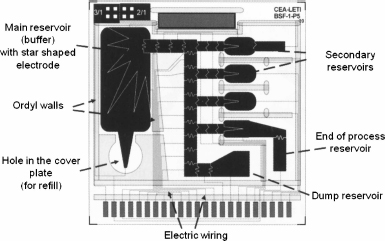
Figure 10.54 shows a typical biologic EWOD chip with its main, secondary, and dump reservoirs, and the electric wiring. The figure especially shows the complexity of the wiring. The electrodes are most of the time individually addressed. However, some electrodes are often difficult to connect to an electric line; it is also very costly in terms of microfabrication to have two levels of wiring in the substrate. Hence, a technique called “multiplexing” is used to address groups of electrodes without losing their individual functionality. We discuss this technique in the following section.
Figure 10.54 Covered EWOD biochip from LETI.
10.3.8.2 Multiplexing
EWOD chips require a paving of the substrate with electrodes. Some EWOD applications require a large number of electrodes and reservoirs. Addressing each one of the electrodes individually is not always possible if the wires are all in the same plane inside the substrate. However, depending on the travel scheme of the droplets on the chip, some electrodes can be put on the same electric line [34–36]. Consider the design of an open EWOD system with catenaries (fig. 10.55). The system comprises M = 5 electrodes in a row and N = 3 rows. Droplets can be individually handled if it is possible to switch the catenaries to the voltage 0 or V and the electrodes to 0 or V. This would mean having N * M = 15 independent electric wires. The multiplexing of figure 10.55 requires only M + N = 8 electric switches. Of course, multiplexing brings limitations on the sequence of operations that can be realized at the same time.
Figure 10.55 Left: Multiplexing scheme for an open EWOD system with catenae: number of electrodes in a row is M = 5, number of rows N = 3, number of electrical lines M + N = 8, total number of electrodes N*M = 15. Right: EWOD system with multiplexing. Photograph Ph. Dubois CEA-LETI.

Multiplexing is very efficient for systems doing droplet manipulations in parallel. An example of such a microsystem is that of Moon et al. [37]. It realizes the generation of multiple droplets from a reservoir and parallel in-line sample purification of a carrier fluid containing proteins.
10.4 Examples of EWOD in Biotechnology – Cell Manipulation
Cells – if not too adherent to the substrate – can be moved together with the droplet. Applications of digital microfluidic applications have been done for cell separation [38,39] and cell lysis followed by PCR amplification for DNA recognition [40].
To perform the biologic protocol, EWOD is often combined with another technique for the specific transport of cells, such as dielectrophoresis (DEP) [38], optoelectronic tweezers OET [39] or magnetic beads [40,41]. The EWOD protocol is programmed to displace and manipulate the carrier fluid, while the adjoined technique is aimed at manipulating each cell. In the following, we give the examples of combined EWOD/DEP, EWOD/OET and EWOD/magnetic beads manipulation.
10.4.1 DEP and EWOD
DEP and EWOD techniques can be combined to concentrate particles and cells. The schematic of the process is shown in fig. 10.56. The method described here has been developed by Fan and colleagues [38]. In a covered EWOD configuration – because droplet division will be required later in the process – the central electrode is replaced by an array of parallel thin electrodes; the dispersed cells are successively pulled by attractive dielectrophoresis from one electrode to the other, towards one end of the droplet. After that, droplet separation is triggered by EWOD, and a concentrated solution is obtained.
Figure 10.56 Manipulation of cells using EWOD and DEP: Cells are progressively pulled into the right part of the droplet, and concentrated by droplet division.
Reprinted with permission from [38]; ©RSC 2008.

Let us recall that the dielectrophoretic force is given by the expression [42]
(10.85) ![]()
where RH is the (hydraulic) radius of the particle or cell, E the electric field (ERMS is the root mean square electric field), εf the liquid permittivity and fCM the Clausius-Mossotti factor. This factor depends on the frequency according to
(10.86) ![]()
where the frequency-dependant electric permittivities are given by
(10.87) ![]()
(10.88) ![]()
where σp and σf are the electric conductivities of the particles and fluid respectively, f is the field frequency and j is the square root of – 1. When the real part of fCM, or Re(fCM), is greater than zero, the dielectrophoretic force FDEP attracts particles toward high field strength regions, which is referred to as positive – or attractive – DEP. Conversely, a negative Re(fCM) generates negative – or repulsive – DEP, which repels particles from high field strength regions. Very often (for cells for example) there is a change between negative and positive DEP with the frequency.
10.4.2 EWOD and OET
Shah and colleagues [39] have demonstrated that EWOD can also be combined with OET, to develop a special OET, called LOET (for lateral-field OET). Again EWOD is used for manipulating the carrier fluid. In contrast to the preceding application using DEP, cells are individually manipulated by OET. The advantage is that a single cell can be isolated in a droplet. The principle is shown in figure 10.57. The LOET uses interdigitated electrodes overlapping the EWOD actuation electrodes. It has been demonstrated that HeLa cells have been isolated in separated droplets with this method.
Figure 10.57 Principle of cell manipulation combining EWOD and OET [38] (LOET stands for lateral-field OET).

10.4.3 EWOD and Magnetic Beads
EWOD and magnetic force can also be combined. A demonstration has been made by Yizhong Wang and colleagues [41]. Recently, the principle of gene analysis in EWOD systems using magnetic beads has been established [40]: first, cell lysis is realized in a sessile droplet in an open EWOD system; second functionalized super-paramagnetic beads are added to capture the specific mRNA; then the targets are extracted by magnetic force out of the “mother” droplet. Finally a PCR is done to amplify the mRNA, allowing for detection.
The demonstration of extracting beads and targets from the droplet is shown in figure 10.58. The figure shows an open EWOD device (with catena) and a droplet containing magnetic beads aggregated by a mini-magnet placed below the substrate. If the electrowetting forces and the magnetic forces are sufficient, the magnetic aggregate separates from the droplet.
Figure 10.58 Combination of magnetic forces exerted on an aggregate of magnetic beads and electrowetting forces exerted on a conductive liquid droplet. In this case, the magnetic forces are sufficiently strong to pin the aggregate and the electrowetting forces are sufficiently large to move the droplet, leaving behind the aggregate with a small amount of liquid (photo CEA-LETI).

10.5 Examples of Electrowetting for Optics – Tunable Lenses and Electrofluidic Display
Electrowetting is a technique well adapted to optical applications [43–45]. In the following sections, we indicate applications of electrowetting for tunable liquid lenses and for screen display.
10.5.1 Tunable Lens
Electrowetting can be used to build tunable lenses. Berge, one of the founders of EWOD with the eponymous BLY equation, is at the origin of the development of such lenses (www.varioptic.com). The principle is directly based on the electrowetting principle (fig. 10.59) with an aqueous, conductive phase and an organic, nonconductive phase. When not actuated, because the electrodes surface is treated hydrophobically, the oil phase partially wets the electrodes and the interface between oil and water is concave (relative to the oil phase). When actuated, the contact angle of the water with the electrodes decreases, and the interface shape changes progressively with the magnitude of the actuation voltage. Above a certain voltage, the interface becomes convex (relative to the oil phase), and the focal point can be adjusted by tuning the magnitude of the applied voltage.
Figure 10.59 Schematic of a tunable lens actuation: left, the electrodes are actuated and the interface is convex (respectively to the oil phase); right, the electrodes are not actuated and the interface is concave (respectively to the oil phase).

10.5.2 Electrowetting Display
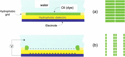
Electronic display can be designed using electrowetting [46]. The principle is shown in figure 10.60: a screen is composed of rectangular windows separated by a solid grid. Each window is a very/super-hydrophobic EWOD electrode which, when switched off, is covered by a fluorescent oil film. Once an electrode actuated, the oil film is repelled in the corners, and replaced by water. A digital screen is thus realized.
Figure 10.60 Principle of electrowetting display: (a) fluorescent oil totally wets the hydrophobic electrode (electrode off); (b) upon actuation, oil is repelled in the corners, and the water wets the electrode.
10.6 Conclusion
In this chapter, the principle of electrowetting and especially EWOD has been presented. It has been shown that such a principle could move droplets digitally on an electrode-paved substrate, and realizes the basic operations required to manipulate droplets. Extremely small volumes of liquids can be used and a low electric power is sufficient.
Applications of such a technique are twofold: biotechnology and optofluidics. In biotechnology, fast PCRs have been realized showing the same sensitivity as the conventional PCRs. New fields of application are sought in cellular biomicrofluidics. In optofluidics, many applications are emerging, from electronic paper [47] to optical switches, and to electrowetting and electrofluidic displays.
10.7 References
[1] A. Wixforth, J.P. Kotthaus, and G. Weimann, “Quantum Oscillations in the Surface-Acoustic-Wave Attenuation Caused by a Two-Dimensional Electron System,” Phys. Rev. Lett. 56, p. 2104, 1986.
[2] http://www.advalytix.com/advalytix/applications_1329.htm.
[3] J. Berthier. Microdrops and Digital Microfluidics. William-Andrew Publishing. 2008.
[4] G. Lippmann, “Relations entre les phénomènes électriques et capillaires,” Ann. Chim. Phys. 5, p. 494, 1875.
[5] B. Berge, “Electrocapillarity and wetting of insulator films by water,” Comptes rendus de l’Académie des Sciences, Séries II, 317, pp. 157–163, 1993.
[6] P. Perrot. A to Z of Thermodynamics. Oxford University Press, 1998.
[7] R.P. Feynman, R.B. Leighton, M. Sands, The Feynman lectures on physics II, Addison-Wesley, Section 8–2, 1977
[8] T.B. Jones, J.D. Fowler, Young Soo Chang, Chang-Jin Kim, “Frequency-based relationship of electrowetting and dielectrophoretic liquid microactuation,” Langmuir 19, pp. 7646–7651, 2003.
[9] T.B. Jones, “An electromechanical interpretation of electrowetting,” J. Micromech. Microeng. 15, pp. 1184–1187, 2005.
[10] Kwan Hyoung Kang, “How electrostatic fields change contact angle in electrowetting,” Langmuir 18, pp. 10318–10322, 2002.
[11] Jun Zeng, T. Korsmeyer, “Principles of droplet electrohydrodynamics for lab-on-a-chip,” Lab Chip 4, pp. 265–277, 2004.
[12] M. Vallet, B. Berge, “Limiting phenomena for the spreading of water on polymer films by electrowetting,” Eur. Phys. J. B 11, p 583, 1999.
[13] T.A. Driscoll, L.N. Trefethen, Schwarz-Christoffel mapping, Cambridge University Press, 2002.
[14] S. Thamida, H.-C. Chang, “Nonlinear electrokinetic ejection and entrainment due to polarization at nearly insulated wedges,” Phys. of Fluids 14, p. 4315, 2002.
[15] H.J.J. Verheijen, M.W.J. Prins, “Reversible electrowetting and trapping of charge: model and experiments,” Langmuir 15, p. 6616, 1999.
[16] V. Peykov, A. Quinn, J. Ralston, “Electrowetting: a model for contact angle saturation,” J. Colloid Polym. Sci. 278, pp. 789–793, 2000.
[17] A. Quinn, R. Sedev, J. Ralston, “Influence of the electrical double layer in electrowetting,” J. Phys. Chem. B. 107, pp. 1163–1168, 2003.
[18] J. Berthier, Y. Fouillet, Ph. Clementz, O. Raccurt, D. Jary, P. Claustre, and C. Peponnet, “An analytical model for the prediction of microdrop extraction and splitting in digital microfluidics systems,” Proceedings of the 2005 NSTI Nanotech Conference, Anaheim, Ca, USA, May 8–12, 2005, pp. 664–667.
[19] S.J. Dodd, “A deterministic model for the growth of non-conducting electrical tree structures,” J. Phys. D: Appl. Phys. 36, pp. 129–141, 2003.
[20] S.M. Lebedev, O.S. Gefle, Y.P. Pokholkov, E. Gockenbach, H. Borsi, V. Wasserberg, N. Abedi, and J. Szczechowski, “Influence of high-permittivity barriers on PD activity in three-layer dielectrics,” J. Phys. D: Appl. Phys. 37, pp. 3155–3159, 2004.
[21] J. Berthier, Ph. Dubois, Ph. Clementz, P. Claustre, C. Peponnet, Y. Fouillet, “Actuation potentials and capillary forces in electrowetting based Microsystems,” Sensors and Actuators, 134(2), pp. 471–479, 2007.
[22] H. Moon, S. K. Cho, R.L. Garrell, and C-J Kim, “Low voltage electrowetting-on-dielectric,” Journal of Applied Physics 92(7), pp. 4080–4087, 2002.
[23] S.K. Cho, H. Moon, and C-J Kim, “Creating, transporting, and merging liquid droplets by electrowetting-based actuation for digital microfluidics circuits,” Journal of Micro-electromechanical systems 12(1), pp. 70–80, 2003.
[24] N. Moumen, R.S. Subramanian, J. McLMaughlin, “The Motion of a Drop on a Solid Surface due to a Wettability Gradient,” Langmuir 21, pp. 11844–11849, 2003.
[25] M.K. Chaudhury, G.M. Whitesides, “How to make water run uphill,” Science 256, pp. 1539–1541, 1992.
[26] J. Berthier, P. Silberzan. Microfluidics for Biotechnology. Second Edition, Artech House, 2010.
[27] Chao-Yi Chen, E. F. Fabrizio, A. Nadim, J. D. Sterling, “Electrowetting-based microfluidics devices: design issues,” 2003 Summer Bioengineering Conference, Sonesta Beach Resort in Key Biscayne, Florida, USA, June 25–29, 2003, pp. 1241–1242.
[28] A. Dolatabadi, K. Mosheni, A. Arzpeyma, “Behavior of a moving droplet under electrowetting actuation: numerical simulation,” Canadian Journal of Chemical Engineering 84, pp. 17–21, February 2006.
[29] M.G. Pollack, A.D. Shenderov, R.B. Fair, “Electrowetting-based actuation of droplets for integrated microfluidics,” Lab Chip 2, pp. 96–101, 2002.
[30] T.P. Lodge, “Reconciliation of the molecular weight dependence of diffusion and viscosity in entangled polymers,” Physical Review Letters, 83(16), pp. 3218–3221, 1999.
[31] J. Berthier, Ph. Clementz, O. Raccurt, D. Jary, P. Claustre, C. Peponnet, and Y. Fouillet, “Computer aided design of an EWOD microdevice,” Sensors and Actuators A: Physical 127, pp. 283–294, 2006.
[32] J. Berthier, Ph. Clementz, J-M Roux, Y. Fouillet, C. Peponnet, “Modeling microdrop motion between covered and open regions of EWOD microsystems,” Proceedings of the 2006 Nanotech Conference, Boston, USA, May 7–11, 2006.
[33] P-G de Gennes, F. Brochard-Wyart, D. Quèrè, Drops, bubbles, pearls, waves. Springer, New-York, 2004.
[34] T. Ondarçuhu, “Total or partial pinning of a droplet on a surface with chemical discontinuity,” J. Phys. II France 5, pp. 227–241, 1995.
[35] Fei Su, Krishnendu Chakrabarty, R.B. Fair, “Microfluidics-based biochips: Technology issues, implementation platforms and design-automation challenges,” IEEE Transactions on Computer-Aided Design and Integrated Circuits and Systems 25(2), Feb. 2006, pp. 211–223.
[36] M. Armani, S. Walker, B. Shapiro, “Modeling and control of electrically actuated surface tension driven microfluidic systems,” Proceedings of the 13th Mediterranean Conference on Control and Automation, Limassol, Cyprus, June 27–29, 2005, pp. 131–138.
[37] K. Chakrabarty and F. Su, Digital Microfluidic Biochips: Synthesis, Testing, and Reconfiguration Techniques. CRC Press, Boca Raton, FL, 2006.
[38] Hyejin Moon, A. R. Wheeler, R. L. Garrell, J. A. Loob, Chang-Jin “CJ” Kim, “An integrated digital microfluidic chip for multiplexed proteomic sample preparation and analysis by MALDI-MS,” Lab Chip 6, pp. 1213–1219, 2006.
[39] Shih-Kang Fan, Po-Wen Huang, Tsu-Te Wang and Yu-Hao Peng, “Cross-scale electric manipulations of cells and droplets by frequency-modulated dielectrophoresis and electrowetting,” Lab Chip 8, pp. 1325–1331, 2008.
[40] G. J. Shah, A. T. Ohta, E. P.-Y. Chiou, Ming C. Wuc and Chang-Jin “CJ” Kim, “EWOD-driven droplet microfluidic device integrated with optoelectronic tweezers as an automated platform for cellular isolation and analysis,” Lab Chip 9, pp. 1732–1739, 2009.
[41] A. Rival, C. Delattre, Y. Fouillet, C. Chabrol, F. Bottausci, G. Catellan, N. David, X. Gidrol, F. Vinet, D. Jary, “Towards Single Cell Gene Expression on EWOD Lab On Chip,” Proceedings of the 2009 Nanobio-Europe Conference, Grenoble, France, 16–18 June 2009.
[42] YizhongWang, Yuejun Zhao and Sung Kwon Cho, “Efficient in-droplet separation of magnetic particles for digital microfluidics,” J. Micromech. Microeng. 17, pp. 2148–2156, 2007.
[43] T. B. Jones. Electromechanics of particles. Cambridge University Press, 1995.
[44] G. Beni and S. Hackwood, “Electro-wetting displays,” Applied Physics Letters 38, pp. 207–209, 1981.
[45] J. Heikenfeld, N. Smith, M. Dhindsa, Kaichang Zhou, Murali Kilaru, Linlin Hou, Jilin Zhang, E. Kreit and B. Raj, “Recent progress in arrayed electrowetting optics,” Optics and Photonics News 21 (1), pp. 20–26, January 2009.
[46] http://documents.epfl.ch/groups/s/si/si-unit/www/nano-bio-sensing/Wu_EPFL1.pdf.
[47] J. Heikenfeld, K. Zhou, E. Kreit, B. Raj, S. Yang, B. Sun, A. Milarcik, L. Clapp, and R. Schwartz, “Electrofluidic displays using Young-Laplace transposition of brilliant pigment dispersions,” Nat Photon 3, pp. 292–296, 2009.
[48] R. A. Hayes, B. J. Feenstra, “Video-speed electronic paper based onelectrowetting,” Nature 425, 383–385, 2003.