
Thermal Energy Storage Systems Design
Abstract
The design of thermal energy storage (TES) system plays a significant role in achieving energy redistribution requirements when integrated with a dedicated cooling or heating system. The sizing of the thermal storage system as a function of demand load profile and on the basis of operating strategies can effectually achieve reduction in chiller load during electrical peak periods. The design methodology of TES systems incorporating flexible provisions to include or change operating strategies depending on the changing load demand can result in a more promising way of shifting the peak load demand to off-peak periods. The operating strategies of TES systems can be designed to fully utilize excess storage capacity during low demand periods, which would enable reduction in overall operating costs of the system.
10.1 Introduction
The most important part of recommending thermal energy storage (TES) systems, either sensible heat or latent heat, to be integrated with the cooling/heating systems in buildings essentially depends on their inherent design aspects. To enable thermal storage systems as fully functional, some crucial factors need to be considered during the design phase, which include the following:
• Thermal load (cooling/heating) profile of the building under consideration
• Type of TES system (e.g., full storage or partial storage)
• Selection of proper heat storage material
• Mode of operation (e.g., active or passive system)
• Availability periods of power supply
• Cooling/heating plant redundancy
• Space availability
• Capital and operating costs
In this context, the basic design of some sensible and latent TES systems with example calculations are demonstrated in forthcoming sections.
10.2 Sensible heat storage systems
In the sensible heat storage system, the quantity of heat energy that can be stored in the material (solid or liquid) by virtue of raising the temperature can be expressed as
Equation (10.1) can be expressed in another form as
where m is the mass of the storage medium, Th and Tl are the maximum and initial temperature of the material (K), and (Th − Tl) is referred to the temperature swing (K).
The volume (in m3) of the material that is required to store a given quantity of heat energy can be calculated by
where, d is density of the material (kg/m3).
The volume of the material required can also be estimated using the relation given by
where, cp is specific heat of the storage material (kJ/(kg K)).
For a typical office space subjected to a temperature swing of 2 °C, the quantity of energy that can be stored is about 0.250 MJ/m2. For an industrial space undergoing a temperature swing of 3 °C, the amount of energy that can be stored is about 0.370 MJ/m2. Thus, the quantity of sensible heat energy storage can be expressed as
where, E is thermal energy being stored (kJ) and A is floor or building area (m2).
10.3 Latent Heat Storage Systems
From the perspective of latent heat storage systems, thermal energy can be stored or released by virtue of the phase transition process of a material occurring at or near isothermal conditions. The change in the state of the material from either liquid to solid (freezing) or solid to liquid (melting) is the key phenomenon for enabling the TES in phase change materials. The change in the latent heat enthalpy of the material during the freezing and melting processes determines the storage capacity of phase change materials (PCMs). This physical process can be suitably expressed in the form as given by
where, H is latent heat enthalpy of the heat storage material (kJ/kg).
The simple design procedures for ice thermal energy storage (ITES) and chilled water-packed bed TES systems are presented in forthcoming sections:
10.3.1 Sizing of ITES system
Inputs for design of ITES system:
Requirement of cooling energy on daily basis—3000 kWh
Time of charging (freezing) of the ice storage—8 h
Time of discharging (melting) of the ice storage—10 h
Peak cooling load demand persisting in the building space—500 kW
A rotary screw type chiller (cooling plant) considered
Energy storage efficiency factor—0.95 (assumed)
Storage capacity—50%
Estimation of the ice storage capacity:
The energy generation requirement on a per day basis can be determined by
Thus, Eg = 3000 × (50/100) = 1500 kWh
The total energy storage capacity can be evaluated by
Thus, ET = 1500/0.95 ≈ 1580 kWh
The charging (freezing) of ice storage using the chilled water medium can be determined by
That is, ice storage charging = (1580/8) = 198 kWh
The chiller cooling capacity during the design day operation can be estimated by

That is, chiller cooling capacity = (1580/10) = 158 kWh.
Thus, the chiller nominal capacity can be determined by

Therefore, chiller nominal capacity = (500 − 158) = 342 kWh.
The chiller plant being selected for charging the ice storage (during nighttime) is capable of shifting the peak load demand in a building during daytime at 50% higher capacity. Hence, the design cooling capacity of the chiller can be estimated to by ≈ 300 kWh (i.e., 198 kW × 1.5).
10.3.2 Sizing of chilled water packed bed LTES system
The design of a chilled water-packed bed LTES system is proposed for a building located in a hot and humid climatic condition. The on-peak and off-peak cooling load requirements are represented by red and blue colors, respectively, in Table 10.1. The total cooling load of the building considered is estimated to be 4130 kW. The efficiency factors for the charging and discharging processes are assumed to be 0.9 and 0.8, respectively.
Table 10.1
Design of the chilled water-packed bed LTES system
| Time (h) | Total Cooling Energy Demand (kW) | Load Satisfied by | Chiller + TES Charging (kW) | TES Balance (kW) | |
| Chiller (kW) | TES Tank (kW) | ||||
| 0 | 100 | 164 | 100 | 164 | 353 |
| 1 | 100 | 164 | 100 | 164 | 416 |
| 2 | 100 | 164 | 100 | 164 | 480 |
| 3 | 101 | 164 | 101 | 164 | 542 |
| 4 | 103 | 164 | 103 | 164 | 603 |
| 5 | 101 | 164 | 101 | 164 | 666 |
| 6 | 107 | 164 | 107 | 164 | 722 |
| 7 | 112 | 164 | 112 | 164 | 774 |
| 8 | 120 | 164 | 120 | 164 | 818 |
| 9 | 225 | 184 | 41 | 0 | 777 |
| 10 | 245 | 184 | 61 | 0 | 716 |
| 11 | 270 | 184 | 86 | 0 | 630 |
| 12 | 300 | 184 | 116 | 0 | 514 |
| 13 | 320 | 184 | 136 | 0 | 378 |
| 14 | 300 | 184 | 116 | 0 | 262 |
| 15 | 270 | 184 | 86 | 0 | 176 |
| 16 | 255 | 184 | 71 | 0 | 105 |
| 17 | 245 | 184 | 61 | 0 | 45 |
| 18 | 229 | 184 | 44 | 0 | 0 |
| 19 | 113 | 164 | 113 | 164 | 50 |
| 20 | 110 | 164 | 110 | 164 | 104 |
| 21 | 105 | 164 | 105 | 164 | 162 |
| 22 | 101 | 164 | 101 | 164 | 225 |
| 23 | 100 | 164 | 100 | 164 | 289 |
| Total | 4130 | 1840 | 2290 | 2290 | |
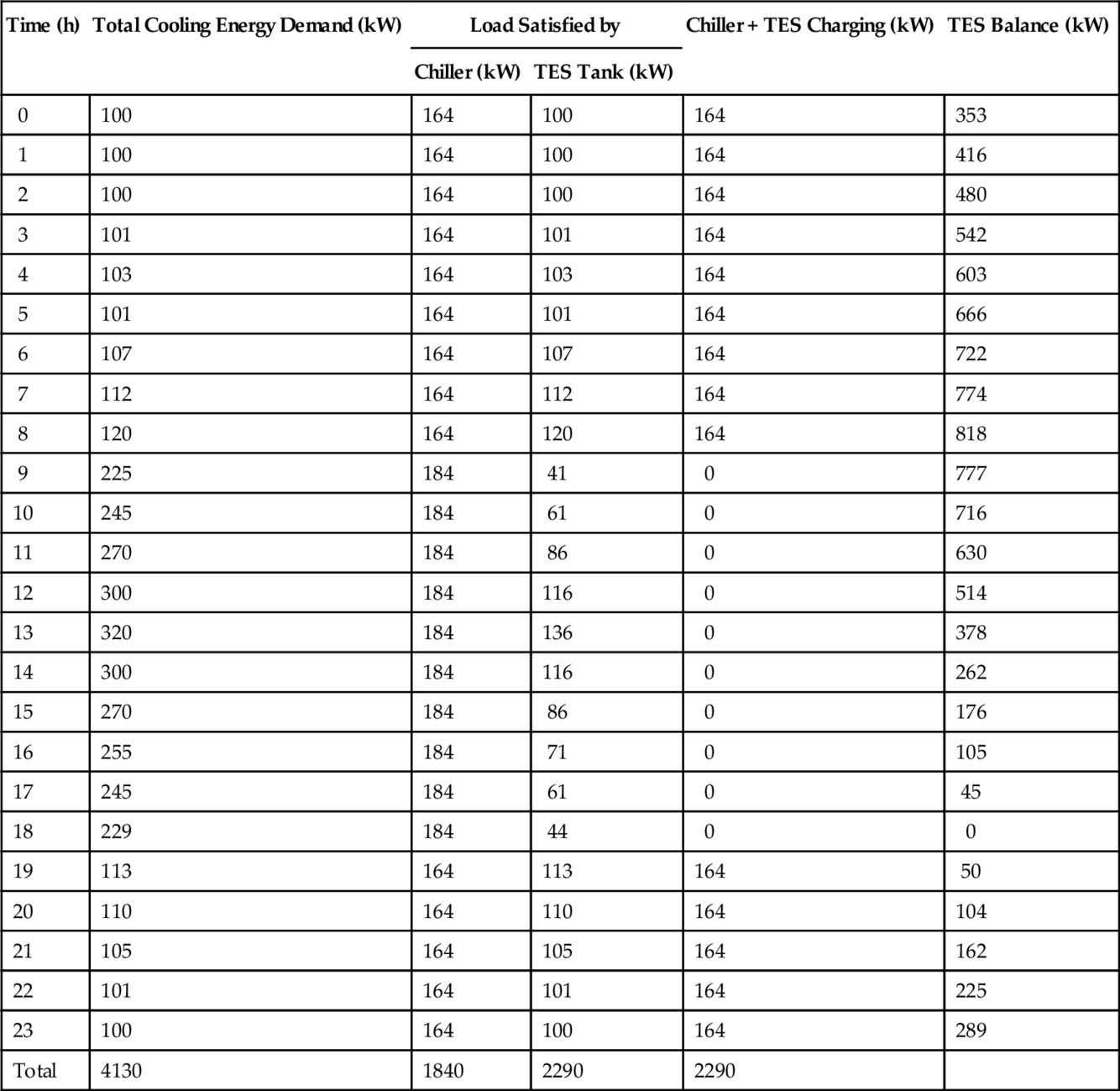
The nominal cooling capacity of the chiller plant can be estimated and is given by
Thus, nominal cooling capacity = (4130/{(14*0.9) + (10*0.8)}) = 204 kW.
The cooling capacity of the chiller during direct cooling (on-peak load conditions) can be determined by
![]()
Likewise, the cooling capacity of the chiller during charging of the LTES system (off-peak conditions) can be obtained by
![]()
The cooling capacity shared by the LTES system (energy redistribution) during on-peak condition can be estimated as follows:
At the commencement of the off-peak load condition (typically at 19 h):
Thus, (cooling capacity of LTES)commencement = (164 − 113) + 0 = 50 kW.
At the completion of the off-peak load condition (typically at 8 h):


Thus, the cooling load shared by LTES during on-peak load conditions can be estimated by
![]()
Therefore, it can be observed from Table 10.1 that the LTES system is completely discharged at 18 h (completion of on-peak load demand period), which signifies that the LTES system is ready for the commencement of the next cycle of the charging process.
10.4 Design Examples
10.4.1 Long-term thermal storage option
For a building cooling application, a chiller of 350 kW cooling capacity is considered to be fully operational for about 720 h. The criteria is to store a minimum annual cooling load, which is given by
![]()
For ice to be used as a latent heat storage medium, for every megajoule of cooling energy, about 3 liters of ice (equivalent to 3 kg) is required.
Thus, the volume of ice required for thermal storage can be determined by

Assuming the depth of the storage tank to be 2 m,
![]()
Considering a cylindrical configuration of the storage tank,
Diameter of the storage tank = (4A/π)^0.5 = ((4*1361)/3.1415)^0.5 ≈ 42 m.
Thus, based on the preceding calculations, it is seen that a very large diameter of the storage tank is actually required for meeting the seasonal cooling energy redistribution requirements in the building. Furthermore, this condition can also be treated as a major constraint in establishing long-term TES options for cooling applications in buildings, which involves additional cost factors.
10.4.2 Short-term thermal storage option
For the same cooling capacity of the chiller as discussed earlier, if the chiller is operated for about 10 h, then the minimum annual cooling load is given by
(Annual cooling load to be stored)min = 350*10 = 3500 kWh
For ice to be used as a latent heat storage medium, for every megajoule of cooling energy, about 3 liters of ice (equivalent to 3 kg) is required.
Thus, the volume of ice required for thermal storage can be estimated by

Assuming the depth of the storage tank to be 2 m,
![]()
Considering a cylindrical configuration of the storage tank,
Diameter of the storage tank = (4A/π)^0.5 = ((4*18.9)/3.1415)^0.5 ≈ 5 m
It is easily observed that the storage tank diameter is almost 8–9 times smaller than to that of the long-term storage option. Thus, the LTES systems can be integrated with building cooling systems, which can be advantageous in meeting the energy redistribution requirements on diurnal or short-term basis.
10.4.3 Short-term thermal storage option in piping systems
The chilled water circulating in the hydronic piping network, which connects the building side with the chiller plant, can be effectively used as a cool thermal storage medium for offsetting the peak load demand in buildings. Usually, the chilled water at a temperature of 8–9 °C is supplied to the cooling coil heat exchanger of the building air handling unit. Reducing the supply temperature of the chilled water by 4 or 5 °C prior to on-peak load conditions can help to reduce the load at the chiller during peaking periods of electricity. For instance, the volume of chilled water in the piping network is considered to be 4000 liters with the chilled water temperature differential remaining at 4 °C, and the refrigeration capacity of the chiller can be estimated by

This means that, 18.7 kWh of thermal energy is stored in the chilled water, which can be utilized an hour prior to the commencement of the on-peak load for experiencing a reduction in the load at the chiller side during electrical peak periods.
Assuming the electricity demand charges for this system to be $10/kW and the coefficient of performance of the chiller to be 3.5, the cost savings on annual basis can be obtained by
![]()
Assuming the cost incurred for a timer and reset control for the system to be $1000, the payback period can be calculated by
![]()
10.4.4 Heating thermal storage option with pressurized water systems
For a domestic hot water application, a pressurized storage system is considered to be integrated with the hot water circuit, in which the water present in the storage tank can be heated up to 135 °C prior to the occurrence of the peak electrical demand period. The hot water can be distributed at 90 °C during the peak period. Assuming 1 liter of water, the additional heat storage capacity of the water can be estimated based on Eq. (10.1) given by
![]()
![]()
For a building with 2600 kW of electric water heating facility and with four pressurized storage tanks with a of volume 9500 liters installed, the storage energy required for the same temperature conditions of hot water as above can be evaluated by
The electrical load reduction for 1 h can be determined by

where, the value of 3.6 is expressed in terms of MJ/kWh.
Assuming the electricity demand charge for this system to be $10/kW and for a heating season period of about 4.5 months, the cost savings on annual basis can be obtained by
![]()
Assuming the cost incurred for the installation of the four pressurized storage tanks and the associated piping network to be $260,000, the payback period can be calculated by
![]()
10.4.5 TES option with waste heat recovery
An industrial batch process is considered in which about 20,000 liters of water at 90 °C are discharged to the drain. By installing a holding tank with a capacity 20,000 liters and a heat exchanger facility, the heat that is wasted from the discharged water can be effectively utilized for heating the incoming makeup water. Assuming the temperature of the water exiting the heat exchanger to be 30 °C, the heat energy being stored in the waste water tank during each drain cycle can be estimated using Eq. (10.1), given by
![]()
Therefore, Q = 5023 MJ
It is understood that roughly 80% of the heat energy can be transferred from the hot water to the incoming makeup water, whereas the remaining 20% can be accounted for inherent thermal losses occurring at the tank and piping elements. The waste heat that is recovered from the heat exchanger can help to reduce the preheating energy required for the gas-fired boiler to heat the incoming makeup water.
Assuming the costing charge for the gas to be $0.50/m3, the cost savings on an annual basis can be obtained by

where, Efe is efficiency of heat exchanger (assumed to be 80%), Cf is fuel cost ($/m3), N is number of tank cycles/year (assumed to be 1000), and Efb is efficiency of boiler (assumed to be 70%).
Therefore, annual cost savings = (5023*0.8*0.5*1000)/(0.7*37.2) = $77,158.
Assuming the cost incurred for the heat exchanger, tank, and associated piping network to be $180,000, the payback period can be calculated by
![]()
The capacity of the TES for this option depends on the volume of the liquid (water) being drained in each tank cycle as well as the temperature gradient between the entering and leaving water at the heat exchanger or heat pump. By properly maintaining the heat exchanger system from contamination or fouling effects, the reduction in the effectiveness of heat transfer can be prevented.
10.5 Concise Remarks
The successful implementation of TES systems for cooling and heating applications primarily depends on the way they are designed to match the purpose. The crucial factors in determining the performance of the TES systems have to be carefully considered during the design phase. The inclusion of modest safety factors into the design of TES systems can help reduce oversizing or underestimation of chiller and storage systems. Flexibility in design methodology is most vital in the sense that it can accept additional storage capacities depending on the future load demand.