
Economic and Societal Prospects of Thermal Energy Storage Technologies
Abstract
Thermal energy storage (TES) on a broad perspective can be thought of as a technology that offers an opportunity to experience relatively low dependency on fossil fuel-based energy sources with reduced energy and electricity costs. The economics of the TES systems can be largely realized on the basis of their successful installation and operation as per design guidelines. The energy-efficient design based on the exergy component of life cycle analysis can help accomplish enhanced cost savings potential of the TES systems on a long-term basis. The proper monitoring and assessment of the underlying factors pertaining to environmental risks on the installation and operation of TES systems can enrich their preference for energy applications toward societal development.
14.1 Introduction
The exploitation of fossil fuel–based energy sources and the increasing demand for energy have shown clear indications for the development and implementation of energy-efficient technologies. The electricity utility sector is continuously striving hard to meet the peak load demand and to do so with optimum generation costs. In this context, TES technologies have been indentified the most promising toward improving energy economy.
Apart from the technical advantages that the TES system would offer, the cost factors involved in their successful implementation and operation in the long run are equally important and have to be considered starting from the commencement to the completion of the project. Establishing proper documentation of the energetic activities or instances occurring during the project phases can help to minimize the overall cost of the TES system being integrated with the cooling/heating system available in the facility. Furthermore, the assessment of the exergy life cycle cost factors in addition to associated energy costs can be beneficial for making an energy-efficient design of the TES systems for future utilization at the facility when required.
14.2 Commissioning of Thermal Energy Storage (TES) Systems
14.2.1 Procedure for installation of thermal storage systems
The operational performance of TES systems mainly depends on the installation procedure, which requires more skill and specialized expertise. Numerous factors are involved in the successful installation of TES systems, some of which include [1,2]:
• Clarity in the objectives of setting up TES systems for long-term benefits
• Cooling/heating load profiles of the facility for which TES system is required
• Technical expertise for operating TES systems
• Analysis of utility ownership and TES requirements
• Estimation of electricity cost savings in the long term
• Establishment of cost rate contract with the electricity utility
• Assessment of heat recovery options using TES systems
• Selection of appropriate control strategies to minimize electricity and operational costs
• Determination of the required cooling capacity redistribution between the cooling/heating systems and TES systems
• Review of design considerations and technical aspects for construction of TES systems
• Establishment of project management coordination between the facility owner, engineer, and contractor
• Verification of the personnel operational expertise and other safety aspects associated in commissioning of TES systems
• Ensuring full operational performance of the TES system through conducting technical checks and required tests prior to acceptance of the installation by the facility owner
• Documentation of activities related to the commissioning and installation of the TES system starting from scheme inception to complete construction of the project
Generically, the TES systems can be considered to provide better energy redistribution ability with low life cycle cost to the facility owner. For instance, the chilled water-based TES system performance largely depends on peak load shifting capacity, operating temperature differential, type of thermal storage strategy considered, and so on. In particular, the design operating temperature differential between the supply and the return chilled water network plays a vital role in determining the storage capacity of the stratified TES system. By maintaining a constant as well as a higher temperature gradient of the chilled water TES system, the stratification occurring in the storage tank can be effective, provided proper control strategies are followed during the operation of the system.
The design of storage tank for a TES system is another crucial task for accomplishing better operational performance of the system in context with the installation procedures. The responsible engineering team has to be a well-trained group of professionals dealing with the design principles and experienced in the installation and commissioning activities of the TES systems. This is due to the fact that an oversized storage tank may lead to higher storage time, cost of construction, and cost of operation. In turn, an undersized tank may affect the desired storage capacity of the TES system.
From this perspective, the facility owner, design engineer, and contractor can refer to the procedures set forth by the International Standards and Codes to gain maximum benefits from installation and operation of the TES systems on a long-term basis. The well-known ASHRAE Standard 150 can be a good reference being designated for describing the testing procedures for establishing the cooling capacities and operational efficiencies of the cool thermal energy storage (CTES) systems.
The ASHRAE Standard 150 refers to the “method of testing the performance of cool storage systems” and includes a functional performance test of a TES system at the completion of its installation in accordance to the project requirements of the facility owner. Overall, the ASHRAE Standard 150 covers testing, instrumentation, test methods and procedures, design data and calculations, and the test report of the CTES systems. To make the CTES systems more functional, they are subjected to performance tests in accordance with the ASHRAE Standard 150, which includes
• Charging and discharging test of the cool storage
• Capacity testing of the cool storage
• Efficiency testing of the cool storage
In short, the commissioning and installation of TES systems are integral processes that evolve from the commencement of the conceptual design to the complete construction phase of a project. The stepwise and sequential documentation of the activities related to the cooling/heating energy redistribution between the utility system and the TES system is most vital for the successful installation and operation of the integrated systems on a long-term basis. Furthermore, the parametric testing of TES in accordance to the International Standards and Codes of Practice along with the project requirements of the owner/client can help sustain energy efficiency at low cost economy of the system.
14.3 Cost Analysis and Economic Feasibility
The installation of TES systems in applications requiring peak load shifting or energy redistribution can be appreciable from the technical viewpoint. However, the preference for TES technologies for real-time cooling/heating applications depends on two important factors, namely, the cost and the economics involved. In this context, the cost analysis and the economic feasibility of latent thermal energy storage (LTES) and seasonal TES systems are discussed briefly in the following section.
14.3.1 LTES system
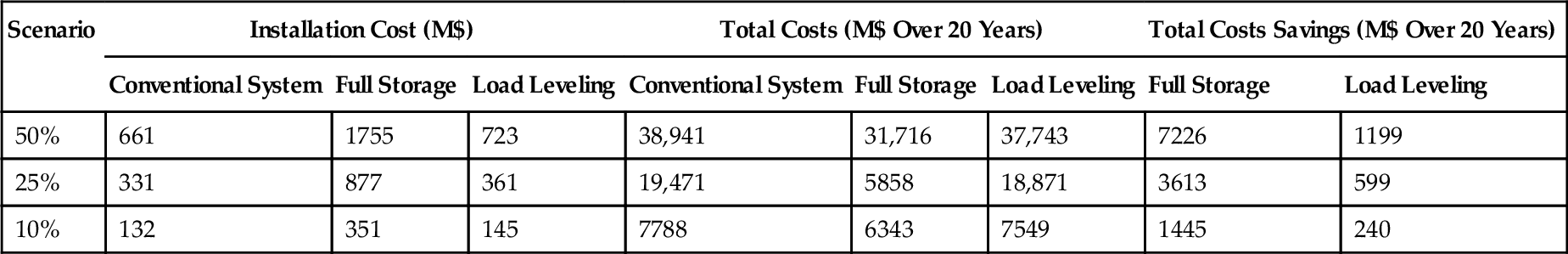
The economic evaluation and the cost savings analysis of the ice thermal energy storage (ITES) system being retrofitted with a conventional A/C system has been studied for an office building located in Malaysia [3]. The long-term benefits of the ITES system over the next 20 years are predicted for three different scenarios. The first scenario is to retrofit for 10% of the conventional A/C system existing in the building, the second and third scenarios being to retrofit 25% and 50% of the existing conventional A/C system, respectively.
Based on the rule of thumb methodology, the capital costs of the retrofit systems are calculated for the three different scenarios. By assuming a steady and constant interest rate of 7% in Malaysia, the utility and the maintenance costs are also predicted for the next 20 years. The prediction results of this study infer that total annual cost of the 50% retrofit ITES system yields 14% cost savings in the best operating condition. Likewise, the other scenarios also result in better cost savings. At the same time, the cost savings potential of full storage is observed to be significantly higher compared to the load leveling strategy.
From the comparison between the installation, maintenance, and electricity costs of the conventional A/C system, it can be seen that the payback period of the full storage ITES system is about 3-6 years. Likewise, the payback period for the load leveling system is found to be between 1 and 3 years. In short, the cost savings achieved through the different operating scenarios of the ITES system facilitate enhanced money savings over the next 20 years for the facility owner, which can be beneficial to society in terms of accomplishing reduced peak load electricity consumption and the reduction of green house gas (GHG) emissions. The test results of the ITES system obtained from this study are presented in Table 14.1.
Table 14.1
Summary of the Test Results of the ITES System [3]
| Scenario | Installation Cost (M$) | Total Costs (M$ Over 20 Years) | Total Costs Savings (M$ Over 20 Years) | |||||
| Conventional System | Full Storage | Load Leveling | Conventional System | Full Storage | Load Leveling | Full Storage | Load Leveling | |
| 50% | 661 | 1755 | 723 | 38,941 | 31,716 | 37,743 | 7226 | 1199 |
| 25% | 331 | 877 | 361 | 19,471 | 5858 | 18,871 | 3613 | 599 |
| 10% | 132 | 351 | 145 | 7788 | 6343 | 7549 | 1445 | 240 |
Other research has studied the operational performance and the cost analysis of LTES system incorporating PCMs with different melting temperature for heating application. Herein, the equivalent money for exergy and the hidden costs associated with the environment have been considered. For achieving a more energy-efficient design of the LTES system, the clearance effect pertaining to exergy analyses on the environment and its equalization with money has been investigated. The schematic representation of the system being investigated is shown in Fig. 14.1, and the thermophysical properties of the selected PCMs are listed in Table 14.2.
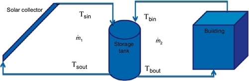
Table 14.2
Properties of Selected PCMs [4]
| PCM Type | Tm °C(K) | Cp (kJ/kg K) | L (kJ/kg) | Density (kg/m3) |
| A32 | 32 (305) | 2.20 | 130 | 845 |
| A39 | 39 (312) | 2.22 | 105 | 900 |
| A42 | 42 (315) | 2.22 | 105 | 905 |
| A53 | 53 (326) | 2.22 | 130 | 910 |
| A55 | 55 (328) | 2.22 | 135 | 905 |
| A58 | 58 (331) | 2.22 | 132 | 910 |

In this LTES system, the total life-cycle-associated economy has been estimated by computing the total energy and exergy lost. Table 14.3 summarizes the results pertaining to the total life cycle cost of this system with each PCM configuration. From the results obtained, it can be observed that the total life cycle cost associated with the exergy lost price decreases with the PCM having higher melting temperature. By virtue of the higher melting temperature and exergy output, inlet and outlet temperatures of the storage are also elevated. Because the exergy input remains constant due to the increase of exergy output, the total exergy lost reduces at a higher melting temperature.
Table 14.3
Total Economic Analyses of the System for 40 Years [4]
| PCM Type | PCM Weight (kg) | PCM Price ($) | Total Price of Lost Energy ($) | Total Price of Lost Exergy ($) | Total Life Cycle Cost ($) |
| A32 | 336 | 2186 | 1,123,439 | 4,447,622 | 5,573,247 |
| A39 | 416 | 2707 | 1,123,439 | 3,561,181 | 4,687,627 |
| A42 | 416 | 2707 | 1,123,439 | 3,193,553 | 4,319,699 |
| A53 | 336 | 2186 | 1,123,439 | 1,904,470 | 3,030,095 |
| A55 | 324 | 2105 | 1,123,439 | 1,679,538 | 2,805,082 |
| A58 | 331 | 2153 | 1,123,439 | 1,347,324 | 2,472,916 |

Table 14.3 shows that the PCM A58, which exhibits higher melting point, yields the lowest total life cycle cost. On the other hand, the contribution of exergy in the total life cycle cost of the system is higher, as can be observed from Fig. 14.2. Hence, the exergy as a major contributor for determination of the total life cycle cost cannot be neglected, and it has to be considered for the energy-efficient design of the LTES system.

14.3.2 Seasonal TES system
The energy and the cost savings of an aquifer TES system in a Belgian hospital facility has been investigated in recent years [5]. The long-term aquifer seasonal thermal storage system is integrated with the reversible heat pumps in order to provide heating and cooling requirements for a newly constructed hospital in near Antwerp. This monitoring study investigates operational performance as well as the economical aspects of the low temperature aquifer SeTES system, as compared to the conventional heating, ventilation and air conditioning (HVAC) installation over the monitoring period of three years. The existing HVAC system comprises a gas boiler and compression cooling equipment to cater the cooling and heating demand in the hospital building.
The cooling and heating load calculations are performed by taking into account the seasonal performance factor of 3.5 for the cooling machine and the gas-fired boiler efficiency of 85%. The pump energy requirements for the HVAC system in the hospital facility are neglected, due to the fact that they remain same while comparison is made between the aquifer thermal energy storage (ATES) and the conventional systems. The design specifications are summarized in Table 14.4, and the schematic representation of this system can be referred from [5]. The effect of this ATES system integration on CO2 emissions over the monitoring period of three years are estimated based on the reference values recommended according to the European Standard EN 15603:2008 [6] as presented in Table 14.5. The comparative results presented in Table 14.6 clearly reveal that the installation of the ATES system has eliminated entirely gas consumption for conditioning the ventilation air and is replaced by the source and heat pumps electricity consumption.
Table 14.4
Design Specifications of the ATES System [5]
| Parameter | Value |
| Maximum flow per well | 100 m3/h |
| Maximum cooling power | 1.2 MW |
| Diameter drilling | 0.8 m |
| Depth wells | 65 m |
| Length filters | 36-40 m |
| Thickness aquifer | 30-40 m |
| Number of cold wells | 1 |
| Number of warm wells | 1 |
| Distance between cold and warm well | 100 m |
| Undistributed groundwater temperature | 11.7 °C |
| Injection temperature warm well | 18 °C |
| Injection temperature cold well | 8 °C |
Table 14.5
Primary Energy Factors and CO2 Emission According EN 15603:2008 [6]
| Total Primary Energy Factor | CO2 Emission Factor (kg/MWh) | |
| European electricity mix (UCPTEa countries) | 3.31 | 617 |
| Gas | 1.36 | 277 |
a UCPTE, Union for the Coordination of the Transmission of Electricity.
Table 14.6
Annual Primary Energy Savings and CO2 Emission Reduction [5]
| Unit | ATES System + Heat Pumps (Installation Klina) | Gas-Fired Boilers + Cooling Machines (Reference-Installation) | |||||||
| 2003 | 2004 | 2005 | Total | 2003 | 2004 | 2005 | Total | ||
| Electricity consumption | MWhe | 343 | 242 | 198 | 782 | 313 | 193 | 242 | 748 |
| Gas consumption | GJ | 0 | 0 | 0 | 0 | 6340 | 5739 | 4884 | 16,964 |
| Primary energy consumption | GJp | 4082 | 2878 | 2362 | 9323 | 12,350 | 10,104 | 9527 | 31,981 |
| Reduction primary energy consumption | GJp | − 8268 | − 7225 | − 7164 | − 22,658 | – | – | – | – |
| % | − 67 | − 72 | − 75 | − 71 | |||||
| CO2 emissions | ton CO2eq | 211 | 149 | 122 | 483 | 681 | 561 | 525 | 1767 |
| CO2 emissions reduction | ton CO2eq | 469 | 412 | 403 | 1284 | – | – | – | – |
| % | − 69 | − 73 | − 77 | − 73 | |||||

In addition, the combined system reduces CO2 emission by more than 1280 tons over the monitoring period of three years. Moreover, the total primary energy savings potential achieved by this combined system for the climatization of the ventilation air is about 71%. This value corresponds to a reduction of 73% of CO2 emission, as compared to the reference installation. On the other hand, the ATES system provides about 46% of total heating energy demand of the hospital facility. Even if the gas-fired boilers are considered, the reduction of CO2 emissions can be still achieved up to 38% with this ATES-heat pump combined system.
Based on the results presented in Table 14.7, it can be observed that the installation cost of the ATES system is comparatively higher and a major cost as compared to conventional/reference installation. This is due to the integral elements of the ATES system including wells, pumps, ducts, heat exchanger, and shutoff valves. Also, the supplemental costs including the geological study and other engineering factors are to be considered in the ATES system installation.
Table 14.7
Economical Analysis of the ATES System Compared to the Reference Installation [5]
| ATES System + Heat Pumps (Installation Klina) | Gas-Fired Boilers + Cooling Machines (Reference-Installation) | ||
| Investment costs | Underground installation (k€) | 299 | – |
| Overground installation (k€) | 266 | 241 | |
| Heat exchangers | 35 | ||
| Pumps, ducts, appendages | 46 | ||
| Control equipment | 116 | ||
| Larger cooling coils | 13 | ||
| Frost protection coils | 32 | ||
| Total installation costs (k€) | 565 | 241 | |
| Extra study and engineering costs for ATES installation (k€) | 130 | – | |
| Total, subsidies excluded (k€) | 695 | 241 | |
| Subsidies (k€) | 244 | – | |
| Total, subsidies included (k€) | 451 | 241 | |
| Fuel costs | Cooling supply (MWh) | 872 | 872 |
| Electricity consumption for cooling (MWh) | 33 | 249 | |
| Total cooling costs (k€) | 3.7 | 27.4 | |
| Heating supply (MWh) | 1335 | 1335 | |
| Gas consumption (MWh) | – | 1571 | |
| Gas costs for heating (k€) | – | 55.0 | |
| Electricity consumption for heating (MWh) | 227 | – | |
| Electricity costs (k€) | 25.0 | – | |
| Total heating costs (k€) | 25.0 | 55.0 | |
| Total fuel costs (k€/year) | 28.7 | 82.4 | |
| Simple payback time | Subsidies excluded (years) | 8.4 | – |
| Subsidies included (years) | 3.9 | – |

Indeed, the energy cost associated with the ATES system installation is comparatively less than the reference installation. That is, about 85% of the energy cost reduction is achievable with the ATES system than with the conventional cooling system installation in the hospital facility considered. The reason for the higher energy cost savings potential of the ATES system is due to the utilization of the natural cooling strategy in the ATES system for sharing the cooling load in the building.
On the other hand, about 55% of the heating energy cost savings is realizable using the ATES system compared to the reference gas-fired boiler installation. Furthermore, even without availing any subsidies, the ATES system is economically feasible with a payback period of 8.4 years. By considering the subsidies, the payback period can be reduced to even less than 4 years.
In this context, the costs of investment per water equivalent of 13 real-time and planned projects on the SeTES systems in Germany are shown in Fig. 14.3. It is obvious from Fig. 14.3 that as the storage volume in water equivalent (storage scale) increases, the investment cost per water equivalent decreases. Based on the survey, it is observed that projects requiring hot water storage exhibit higher costs, which is due to the construction of large storage water tanks.
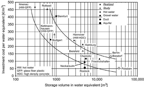
At the same time, the ATES and the borehole TES systems are comparatively cheaper, but geological suitability is a major factor to be considered for their successful installation and efficient operation on a long-term basis. In addition, the inherent heat loss effects of the seasonal storage systems involve supplemental costs for the installation of heat pump units to upgrade of the extracted heat energy to be directly utilized in the building spaces.
14.4 Societal Implications of TES Systems
The utilization of the sensible heat, latent heat, thermochemical, and long-term seasonal TES technologies for the benefit of the society in terms of energy, cost, and economical aspects have been recognized over years. The promising aspects of the TES systems for fulfilling the energy requirements of the society can be realized from the following points:
• Reduction in the extensive usage of fossil fuels–based energy sources
• Reduced greenhouse gas emissions
• Bridges gap between the energy supply and energy demand
• Peak load redistribution to off-peak load periods; thereby less power consumption at the cooling/heating equipment
• Reduced electricity and energy costs
• Increased external financing options and higher property values
• Economic feasibility
On the other hand, there are some major limitations in the successful installation and the operational aspects of the TES systems from the societal point of view, which include
• Issues related to the storage and release of thermal energy at a constant temperature
• Stratification problems in realizing STES systems implementation
• Inherent thermal losses from the storage system by means of conduction and residual stored energy loss
• Space requirements for the installation of the system
• Disposal of the chemically derived PCMs and thermochemically reactive constituent materials into the environment without proper treatment as per the Standards and Regulations
• Operation and maintenance issues
• Economic risk factors between the utility and the facility operations in terms of electricity pricing policy
• Environmental impacts due to the changes in the hydrological, biological, and geotechnical aspects of the underground
• Possibility for the leakages of the heat transfer medium in the underground TES systems
14.5 Concise Remarks
The cost analysis of different TES systems installation discussed indicates possible growth in the economic status of society by means of achieving reduced energy and electricity costs. Next to this, the integration of a TES system with an existing cooling/heating system installation can facilitate for attaining effective energy redistribution needs during peak demand load periods, reduction in the dependency of fossil fuel-based energy source,s as well as greenhouse gas emissions reduction.
To experience the aforementioned promising aspects of the TES systems, their installation procedures starting from the scheme inception to the commissioning stage of the project has to be followed vigilantly. The proper documentation at every step of the project phase involving the economic design aspects are most essential for successful installation and operation of TES systems on a long-term basis. Even though there are certain restrictions in the development of the TES systems, their usefulness has already been realized for socioeconomic development for a sustainable future.