
Chapter 4
Recording formats and timecode
The U-Matic format
The track layout of this format is illustrated in Figure 4.1 for the Hi-Band version. Each video track contains one field of video, recorded by a dedicated head (there are two heads on the scanning drum) and the switching between heads is accomplished during the broad pulses in the vertical interval. There is thus no loss of video information in the original inception of this format.

Figure 4.1 The U-Matic system did not originally provide for a dedicated timecode track.
Timecode was originally recorded on one of the audio tracks, usually Track 1. The sound recording and replay processes are performed by the same heads so there is no timing shift. However, the raw timecode coming off tape had to be regenerated to correct the differentiation and timing jitter that occur on any magnetic analogue replay process. Operational considerations dictated that somewhere else be found for the timecode. Recordists in the field wished to record separate sounds on the two available tracks for later mixing, voice-over recording, or dubbing; editors also needed both audio tracks available for programme sound mixing. A dedicated track for longitudinal timecode was needed, but where could it be put? The answer lay in the property of different recorded wavelengths to penetrate to different depths from the surface of the magnetic medium. Short recorded wavelengths tend to lie close to the surface of the tape, whereas long wavelengths penetrate deeper. Figure 4.2 illustrates the point.
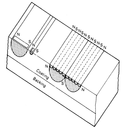
Figure 4.2 Short wavelengths are recorded near the surface of the tape, long wavelengths penetrate deeper. On replay they can be separated by filtering.
The video write speed of a Hi-Band U-Matic is 854 mm/s. The recorded wavelengths of the video are going to be a few micrometres long. The longitudinal speed of the tape is 95.3 mm/s. At 80 bits of LTC per frame, the shortest recorded wavelength will be in the order of 40 (μm. With the video and timecode signals occupying such widely spaced parts of the frequency spectrum, it is easy to ensure that mutual interference is filtered out. The timecode track is inside the two original audio tracks. The video tracks will overwrite the area occupied by this 'address track', as Figure 4.3 illustrates. The process of recording a magnetic imprint deep into the tape layer for later overwriting on the surface is called 'burning in'; however, the term 'burning in' has come to mean the insertion, into the video waveform, of a signal that will allow the timecode to be displayed as human-readable characters, usually in a rectangular box towards the bottom of the screen. This facility can be of assistance in the off-line editing, or daily viewing process.
Depth recording of a timecode track will allow pre-striping of a tape with both code and control track for insert editing (see Chapter 9), but what of re-recording timecode after the video has been recorded? This is no problem as long as the replayed video is processed by a timebase corrector. The time address track will overwrite 11 lines of the recorded video waveform as Figure 4.4 illustrates. The last two active lines in each field, and the field synchronizing pulses of the succeeding field, will be overwritten. Longitudinal timecode on this version of the format is reprocessed by circuitry internal to the machine.
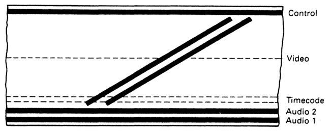
Figure 4.3 Longitudinal timecode can be 'burned in' underneath the video tracks on the U-Matic format.
VITC is not an option on this format because of the bandwidth requirement. Remember that to produce reasonable rectangular pulses of a particular frequency, the 3rd harmonic of that frequency must be present. 90 bits of information put into a 49.655 μs time slot would require a bandwidth of 2.7 MHz. The U-Matic format is not capable of this degree of video resolution unless regularly and carefully maintained.
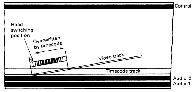
Figure 4.4 If timecode is rewritten it will erase a portion of each video field. Since this contains only field sync information it can be reinserted by the timecase corrector.
The 1in C-format
A C-format VTR possesses a number of heads on the head drum to provide such operational facilities as confidence replay during record, video-only erase, variable-speed play and so on. The format has undergone a number of evolutions since its original introduction, and these will be outlined below. In every version the heads have to break contact with the tape once in each field, as Figure 4.5 illustrates. It can be seen that a head leaves the tape for 14° every revolution. This period is timed to begin in the early part of the field interval. Figure 4.6 illustrates the format dropout that results. The dropout starts after the 4th broad pulse in the vertical interval, and in the PAL implementation of the format has a duration of almost 12 lines. This means that in the PAL version lines 3-14 in fields 1, 3 etc. and lines 315 (in part), 316-326 entirely and line 327 (in part) in fields 2, 4 etc. are lost (10 lines per field are lost in the NTSC version). These lines are replaced by the TBC, so VITC should not be placed in them.
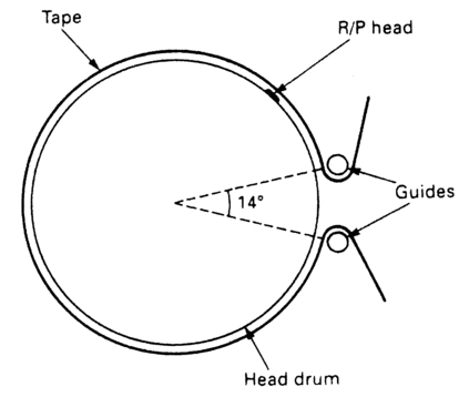
Figure 4.5 The C-format dropout results from the head losing contact with the tape for 14 degrees each revolution.
During variable-speed and stop-frame operation the number of lines subject to format dropout or prone to line time instability may increase, so VITC should not be put too close to this section. The reason for this is that when the tape is running at non-standard speed the effective tape-to-video-head velocity will change slightly so the format dropout duration will alter. When a helical-scan machine plays at a non-standard speed the effective diagonal angle between recorded tracks and the path followed by the video head will differ from that at standard playing speed. This will result in a 'noise bar' at some point in the viewed picture as the replay head crosses tracks. To avoid this, there is the option of providing a video head, known variously as an 'auto scan tracking' (AST) or 'dynamic tracking' (DT) head which will follow the recorded tracks over a wide range of playing speeds including 'stop'. The mounting for this head flexes in response to controlling signals and so is able to follow the slightly different track angle. On some machines the degree of flexibility
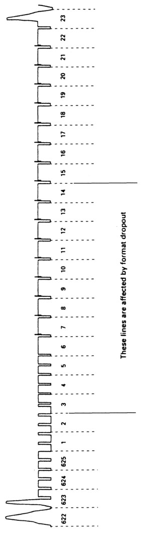
Figure 4.6 Format dropout affects the first lines in each field.
allows the head to track adjacent recorded field tracks, thus giving true frame information rather than a repeat field. This process results in the head requiring some settling time at the start of each track (Figure 4.7) and there may be some line instability at the start of each scanned section of the field. If VITC is present in this section it may be misread. If this occurs the DT or AST head should be switched off if possible. The alternative to losing part of the field interval to format dropout is to provide the information on separate tracks. The C-format originally specified three options for the tracks, which are illustrated in Figure 4.8.
Option 1
Two audio tracks at the top of the tape for programme sound.
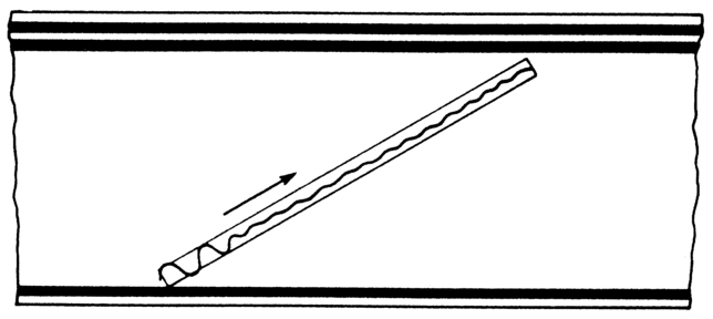
Figure 4.7 DT (AST) heads may require settling time at the start of each track. If this causes problems with VITC, switch the DT function off.
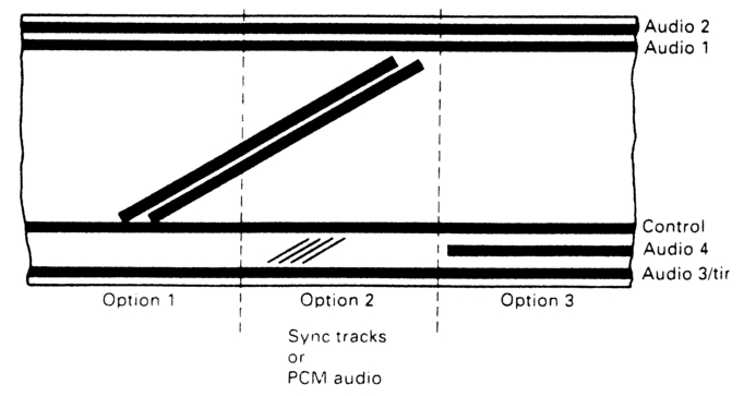
Figure 4.8 Option 1 of the C-form at provides two audio tracks and a third which can carry either audio or timecode as specified. Option 2 can carry either the missing sync information or PCM digital audio as specified. Option 3 carries a fourth audio track.
One audio track at the bottom of the tape for either longitudinal timecode or cue audio.
Control track.
Option 2
Two audio tracks at the top of the tape for programme sound.
One audio track at the bottom of the tape for either longitudinal timecode or cue audio.
Diagonal sync tracks, recorded by a sync head mounted on the scanner, replace the information lost by format dropout and allow some overlap for stability during switching (18.75 lines on EBU versions, 15.75 lines in SMPTE). A recent variation on this option is to record time-compressed PCM sound in these tracks instead of syncs, in which case they will not be available for VITC. These tracks are recorded between audio track 3 and the control track.
Control track.
Option 3
Two audio tracks at the top of the tape for programme sound.
One audio track at the bottom of the tape for either longitudinal timecode or cue audio.
A fourth audio track, recorded between track 3 and the control track.
Control track.
On each of the options, audio track 3 can be combined with a suitable record /replay head and associated electronics to handle the wide bandwidth required to read timecode both at slow jog and high spooling speeds. The electronics associated with a dedicated timecode track will regenerate the code on replay. Code recorded on an unmodified audio track will not give the degree of flexibility required in the post-production environment.
In a PAL environment the longitudinal timecode is recorded at a peak-to-peak level of 185 nanowebers per metre (nWb/m) short-circuit flux. The SMPTE specify a recorded flux of at least 141 nWb/m. At the time of writing the SMPTE proposes that in the 525/60 environment VITC shall be recorded on lines 12 and 14 in C-format VTRs with sync head and lines 16 and 18 in C-format VTRs without a sync head.
Betacam, Beta SP and MII formats
In these systems the colour information is not modulated onto the luminance prior to recording. Instead, luminance and chrominance are handled separately, and recorded on different sections of the tape. The requirements for signal timing are as rigid as in a composite system, since luminance, chrominance and timing pulses all have to register for processing in vision mixers etc.
Within the recorder the luminance (Y) signal is recorded onto alternate tracks, one field per track. There is no need to record the vertical interval pulses as they will be replaced by the machine's internal TBC. The Pr and Pb signals are time-compressed on a line-by-line basis. Alternate lines of Pr and Pb are then recorded one after the other throughout the complete track, so that it consists of alternate Pr and Pb line samples multiplexed along its length. The chrominance tracks are alternated with the luminance tracks on tape.
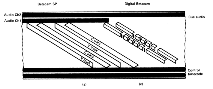
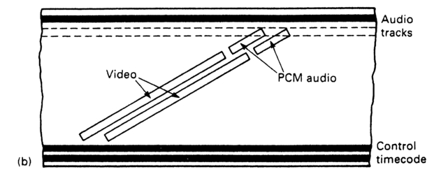
Figure 4.9 (a) The Beta SP format can provide either two analogue longitudinal audio tracks, or one audio analogue track with two digital audio channels, (b) The Mil format provides the same options, although the footprint differs. Both provide for analogue FM audio to be frequency division multiplexed with the chrominance signal, (c) Digital Betacam provides four digital audio channels and a single linear analogue audio track. All three formats carry LTC.
These formats can carry information about the eight-field sequence. Although this is not required in a purely component environment, a recorder may be fed with a composite signal. When this occurs, a colour frame ID pulse is also recorded together with a line of colour framed subcarrier information (vertical interval sub-carrier, or VISC). In the Beta SP format this signal is placed in line 8 (line 11 in NTSC) of the vertical interval to improve the accuracy of colour framing on replay. In the PAL system it runs at half the colour sub-carrier frequency; in the NTSC version it runs at sub-carrier frequency. The Mil format also incorporates a VISC signal, but places it in line 10. In addition, the Mil format indicates colour framing by use of variable-width control-track pulses. The original Betacam format had no provisions for handling VITC, though a modification is available to permit its use. If VITC has been recorded by a modified machine, or a Beta SP machine is loaded with oxide tape, there is the distinct possibility that an unmodified machine will not replay it. Hence the requirement for LTC. Beta SP does support VITC.
Figure 4.9 illustrates the track layouts of the Betacam, Beta SP & MII formats. All formats give a reprocessed longitudinal timecode output on replay. For Beta SP the IEC specifies the recorded flux level of the timecode track as 500 nWb/m short-circuit flux per unit of track width. The SMPTE specify the flux level as being at saturation level. This is the level at which a 1 dB increase in input level results in a 0.5 dB increase in output level.
D-1 component digital format
This video recorder format was developed to record component video in digital form. There is a reasonable quality cue audio track at the top edge of the tape; longitudinal timecode and control tracks at the bottom. The track layout is illustrated in Figure 4.10.
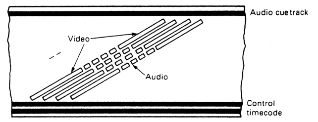
Figure 4.10 The D-1 format carries LTC but has no VITC facility. Digital audio is recorded in the centre of the tape.
The information in one video field is shuffled over several tracks to assist error protection. Because of this, it is inappropriate to rely on VITC alone, as no guarantee can be given that time data incorporated in the video waveform can be read at other than standard speed, which rather defeats the whole purpose of VITC. If digital audio is being fed to the machine via the AES/EBU interface (see Chapter 11), time data could be incorporated in the segmented audio tracks in the centre of the tape. The nature of audio requires a higher degree of error correction, and lower levels of concealment than are appropriate to video. The lower data rate requirements for audio mean that information can be duplicated on different sectors, and in different relative positions, as Figure 4.11 shows. As a result there is an extremely high expectation that audio data with embedded timecode data will be recovered unambiguously.

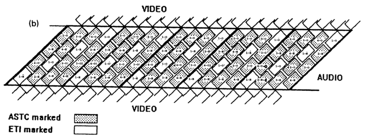
Figure 4.11 (a) Timecode and equipment type information are carried in the even and odd audio sectors respectively, (b) There are 6 audio sectors per video frame in 625/50 systems, and 5 audio sectors per frame in 525 / 60 systems.
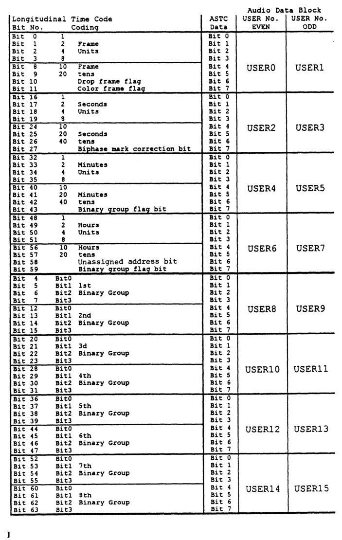
Figure 4.11 (c) The ASTC/ETI data structure. Courtesy of SMPTE Journal.
There is a longitudinal timecode track that can be read over a very wide range of speeds, using biphase mark code. Originally there was provision for two independent timecode words. It was thought useful to have two, so that one could carry the original time addresses from a source tape as a record of its history. However, dual timecode was not taken up and all current machines support standard format LTC. Peak flux level of the timecode track is identical with that specified for C-format.
Audio sector timecode and equipment type information
The D-1 format now supports audio sector timecode and equipment type information. These codes are internal to the VCR and are recorded in the user bit areas of the audio sectors of the helical tracks.
Audio sector timecode (ASTC) can be recorded and edited independently from the audio data by using advance preread heads and rewriting data lifted off in editing or re-recording. It is recorded in odd and even audio segments 2, 3 and 4 (Figure 4.11a), in the user bits. The ASTC word is 64 bits long (there is no provision for synchronizing word or cyclic redundancy check: the data will always be read in the same direction by the scanning head, and the code is repeated several times within each field). As each audio segment is recorded twice in each sector, the ASTC is also recorded twice per sector. There are 6 audio sectors per video frame in 625/50 systems, and 5 sectors per frame in 525/60 systems (Figure 4.11b).
Equipment type information (ETI) is derived from internal manufacturer's settings and is also recordable/editable independently of the audio data. It comprises pairs of data blocks of 8 bytes each, recorded alternately in the odd and even audio 1 segments (Figure 4.11a), in the user bits, giving 16 bytes of data which carry manufacturer identification, machine serial number, head drum (scanner) serial number and DVCR type. There are 4 undefined bytes (currently set at &00). The data in each of bytes 0-11 is coded up as ISO 646 (ASCII) alphanumeric characters as 2 hexadecimal (4 bit) words. Even ETI blocks carry user bytes 0, 2, 4, 6, 8, 10,12 and 14. Odd data blocks carry user bytes 1, 3, 5, 7, 9, 11, 13 and 15. Figure 4.11c illustrates the ASTC/ETI structure.
D-2 composite digital format
The D-2 format was developed to provide, in digital form, the facilities expected of a C-format VTR. The track layout is illustrated in Figure 4.12. This format employs azimuth recording with no guardband between the helical tracks. The audio segments are located at either end of the video data tracks. The format incorporates a longitudinal timecode track. The channel code for LTC is standard biphase mark. It is recommended that LTC be recorded at a level of 250 nWb/m short-circuit flux.
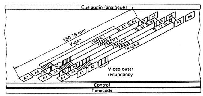
Figure 4.12 The D-2 format provides for timecode to be recorded on a longitudinal track. VITC is also supported.
Some D-2 models support a 'FORMAT' mode which enables an operator to pre-stripe a tape at three times normal speed, with control track and Timecode (generated internally). In the format mode the helical video and audio tracks are not laid down, which means that when editing a formatted tape all channels (video and audio) must be enabled. Formatting also requires the VCR to be fed a stable video feed, locked to reference video.
The format supports VITC, though not over the earlier lines of the range specified in the IEC 625/50 version, because the first few lines of each field are not recorded. This is to ensure that the first recorded segment of each field starts with the identical phase of colour sub-carrier. The details are shown in Figure 4.13. In 525/60 VCRs, VITC can be placed in any of the lines specified as they are always recorded, as Figure 4.14 illustrates. In common with all DVCRs, the audio channels accept the AES/EBU digital interface with its provisions for timecode.
D-3 composite digital format
Developed by National Panasonic, this format use 1/2in metal particles tape. The track layout is shown in Figure 4.15. As with D-2,304 lines/field are recorded in the PAL version. This format provides a range of timecode facilities similar to those provided by D-2.
D-5 digital format
This format uses 1/2in metal particle tape. D-5 VCRs will record and play back CCIR 601 component digital video, but can be provided with the option of replaying D-3 digital composite recordings. The track layout is illustrated in Figure 4.15b, Longitudinal timecode is supported, as is the AES/EBU standard 2-channel interface.
Digital Betacam
Runs at a slightly slower longitudinal speed than Beta SP (96.7 mm/s as opposed to 118.6 mm/s) and has narrower tracks (20 μm as opposed to 86 μm for Y and 73 μm for Chroma). AES/EBU digital audio is supported, and carried in the audio sectors located in four segments in the centre of each helical track (Figure 4.9c). D-VITC can be supported as an option. LTC is carried on an outside track below the control track.
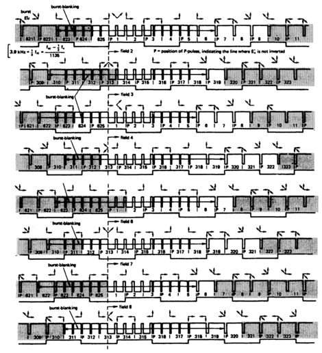
Figure 4.13 D-2 records 304 lines in PAL. The 1st line changes from field to field so that each field commences with the same line type. This aids colour processing in shuttle.
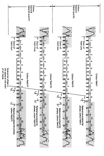
Figure 4.14 The recorded lines in the NTSC version vary from field to field. The first recorded line is chosen to ensure all fields start with the identical sub-carrier phase.

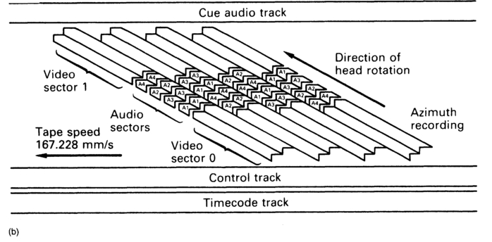
Figure 4.15 (a) The D-3 employs azimuth recording to lay down eight tracks of digital video as one field, (b) The D-5 also employs azimuth recording, this time to lay down CCIR 601 component video. Both formats support longitudinal timecode.
DV
Overview
Digital video is a format implemented by the Sony Corporation as DVCAM™, by Panasonic as DVCPRO™ and by JVC as Digital-S™. There are a variety of lightweight (ENG) and consumer/prosumer versions such as MiniDV™. The format employs 6.35 mm (1/4in) wide metal particle tape. Video is compressed by 5:1, audio is 16-bit stereo at 48 kHz sampling locked to video. All manufacturers use the same video data format, though there are differences in timecode implementation (consumer versions do not support IEC timecode) and in other facilities provided (DVCPRO does not implement DVCAM's ability to store cueing points in a cassette-based microchip). There are options for transferring recorded audio and video data, as well as timecode, as MPEG-2 via IEEE 1394. The IEEE 1394 standard specifies a high-speed serial data bus capable of over 393 Mbit/s bit rates. It can be 'hot wired' unlike SCSI interconnections and has been implemented by a number of manufacturers in 'Prosumer' acquisition and editing equipment as 'Firewire™'. Though at present it requires a 6-wire copper link (two screened pairs for data transfer and one unscreened pair for d.c. power) or a traditional fibre-optic link, and can be carried over distances of up to 4.5 m over copper and up to 100 m over fibre-optic, Plastic optical fibre is being developed that should make for much more convenience.
DV timecode
There is no longitudinal timecode track as Figure 4.16 illustrates but LTC is supported and VITC can be, though at the time of writing there is no standard for VITC. Apart from the helical tracks there is a cue audio track and a control track. The helical tracks are arranged in blocks of 10 tracks per frame for 525/60 systems and in blocks of 12 tracks per frame for 625/50 systems. LTC is recorded in the subcode area of the helical tracks (Figure 4.17) and VITC (if supported) could be recorded in the reserved areas of the video auxiliary data area (Figure 4.18). At present some manufacurers place timecode data concerning start/stop times of takes in this area, though again there is no agreed standard at the time of writing. Additionally, the video and audio auxiliary data areas carry such information as copy management data, aspect ratio, audio sampling frequency, number of audio samples per video frame etc. Although the audio signals are recorded separately from the video, the data are arranged as frames to coincide with the video in blocks of either five tracks (525/60) or six tracks (625/50).
Similarly, timecode data recorded in the subcode area are recorded in
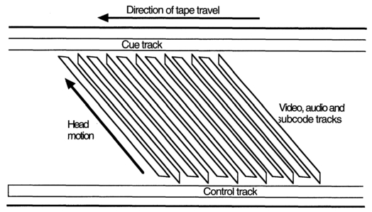
Figure 4.16 The DV track format. There are 12 tracks per field in 625/50 systems (10 in 525/60 systems). Timecode data are embedded into the subcode sectors of the helical tracks.
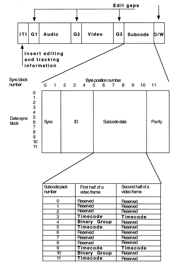
Figure 4.17 Each DV helical track is segmented into ITI, Audio, Video and Subcode sectors. Timecode is carried in packs 3, 4, 9, 10 and 11 within the subcode sector.
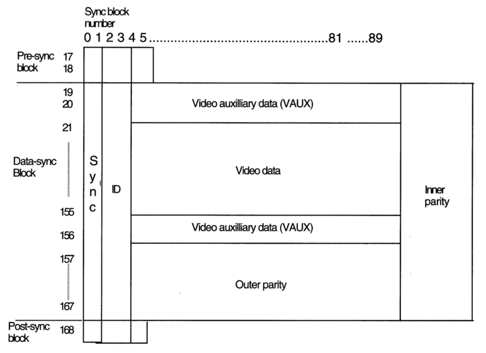
Figure 4.18 Within the DV Video sector are auxiliary data (VAUX) areas. There is space within these areas for the storage of VITC. Although proposals have been made for storing VITC in the VAUX area, no standard has been agreed and the proposal has not been implemented.
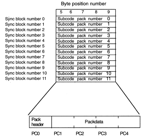
Figure 4.19 Each subcode pack within a DV sync block carries a pack header byte followed by 4 bytes of data. The data bytes can carry timecode information.
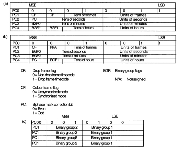
Figure 4.20 The bit arrangement within the DV subcode packs for (a) 625/50 version timecode, (b) 525/60 version timecode, (c) Binary Groups.
packs in groups of five or six tracks, referred to as either the 1st or 2nd halves of a video frame. In the 525/60 version, tracks 0, 1, 2, 3 and 4 comprise the 1st half, and tracks 5, 6, 7, 8 and 9 form the 2nd half. Tracks 0,1,2,3,4,5 and tracks 6, 7, 8, 9, 10, 11 form the 1st and 2nd halves respectively for 625/50 systems. Figures 4.19 and 4.20 show how the timecode data are mapped within the subcode area. On replay, LTC stored in the subcode area is reprocessed and appears at the output as standard IEC timecode.
DV, MPEG-2 and IEEE1394 (FirewireTM)1/2
The DV data packaging for playout is similar to the packetized elementary stream (PES) employed by MPEG-2, which allows the option of carrying DV in the MPEG-2 transport streams as Figure 4.21 illustrates. At the time of writing no standard has been agreed for the transport of IEC timecode on MPEG-2, and although MPEG-2 data carry timestamps, as was shown in Chapter 3, these are essentially 'helper signals' for the decoder and do not have the frequency of occurrence necessary for implementing traditional timecode provision.
The Hi-8 video format
The track layout is illustrated in Figure 4.22. There are two longitudinal tracks. The track designated 'cue' is optional; the other carries analogue audio. The helical tracks carry video and FM audio. There is provision for an optional PCM audio sector within each of these tracks. There is no control track (though the cue track may in future be used for this purpose), its function being performed by a pilot signal recorded along the helical tracks. Each track carries one field of information.
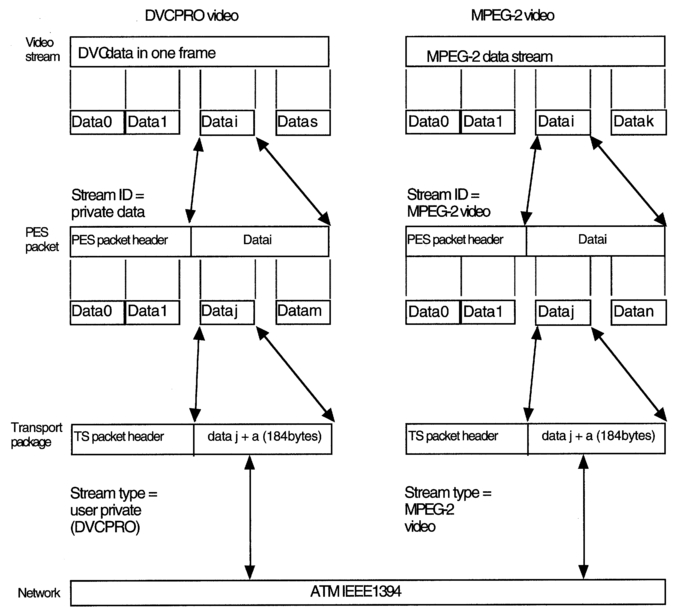
Figure 4.21 DV data packaging is very similar to that employed in MPEG-2 and both can be networked via IEEE 1394 (Firewire™). This has enabled professional and consumer versions of DV to merge into a 'prosumer' system.
There is provision within the PCM sector for six optional time information modes. The data are carried in four identification (ID) words. The individual modes are flagged by another 8-bit ID word, and a further ID word carries control information. These words are interleaved with the digital audio data. The assignment of these words is illustrated in Figure 4.23. The mode is flagged by the ID0 word:
- Mode 1: Tape counter in hours, minutes, seconds and frames from start of tape.
- Mode 2: Programme no. I, which indicates the programme number, take number, together with minutes and seconds from the start of each take.
- Mode 3: Date in year, month, day of month and day of week.
- Mode 4: Time of recording (time of day) in hours, minutes and seconds.
- Mode 5: Programme no. II, which indicates the programme number together with hours, minutes and seconds from the start of programme.
- Mode 6: Index, which is the programme number together with the time in hours, minutes and seconds from the start of the tape.
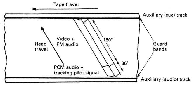
Figure 4.22 The footprint of the Hi-8 format has the option of PCM audio. Time data may be interleaved with audio data at the time of recording.
Domestic and professional R-DAT
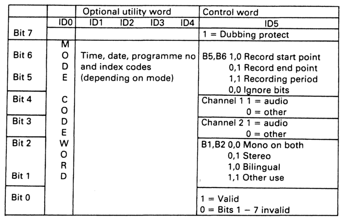
Figure 4.23 The time data in Hi-8 are recorded in optional utility words within the PCM audio segments.
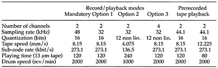
This digital audio recording format was originally intended for domestic use. It achieves a recording time of two hours. Helical-scan azimuth recording is employed. There is no control track, its function being performed by automatic track-finding (ATF) sectors within the tracks. The track layout is shown in Figure 4.24. There are two optional longitudinal tracks provided, one at either edge of the tape. Timecode is recorded in the sub-data areas at either end of each audio data area. The normal tape speed is 8.15 mm/s, but different speeds are available, with three different basic sampling rates, 48 kHz (47.952 Hz for NTSC dropframe working), 44.1 kHz and 32 kHz. Domestic consumer versions of the format do not permit recording at the 44.1 kHz sampling rate. This is to deter direct digital copying of compact discs. There are two quantization standards. Table 4.1 illustrates the options available.
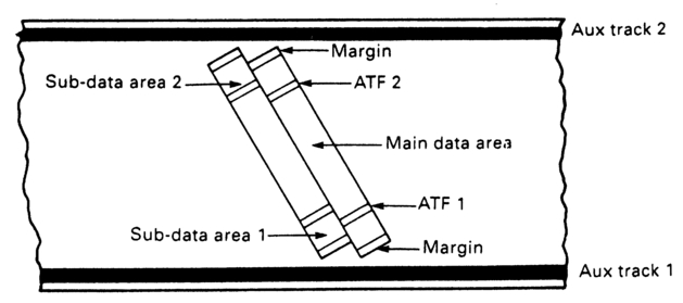
Figure 4.24 The R-DAT footprint places timecode within the subdata areas at the ends of each track.
The three 32 kHz modes are designated for the following applications:
- Mode 1: Current broadcast and satellite television standards.
- Mode 2: Extra long play (longitudinal tape speed is halved).
- Mode 3: 4-channel recording.
The digital data are recorded in blocks of 288 bits. There are 196 blocks to one track. Each track contains 16 blocks of sub-code data in addition to audio (8 at each end of the track). The azimuth recording system employed results in the natural formation of track pairs (Figure 4.25). Each track pair is regarded as a frame, with audio data being conformed into frames for the purposes of editing. The duration of each frame is 30 ms (a frame rate of 33.3 fps).
In its original domestic incarnation, the time data recorded in the subcode areas performed the functions of a sophisticated tape timer, providing three versions of tape time:
- A — Time: Absolute time from the beginning of the tape
- R — Time: Running time from the beginning of the recording
- P — Time: Time from start of each programme item
Table 4.1 The R-DAT options compared. 48 kHz record/play and 44.1 kHz replay only are mandatory.
Broadcasters were not slow to realize the value of the portable R-DAT machine. However, its usefulness as a post-production tool was limited by its inability to synchronize with other machines. As a result of pressure brought about by professional users, manufacturers and standards organizations acted to incorporate the IEC timecode into the format, together with video locking facilities, and to provide studio version machines with interface facilities that permitted communication with edit controllers and synchronizers.
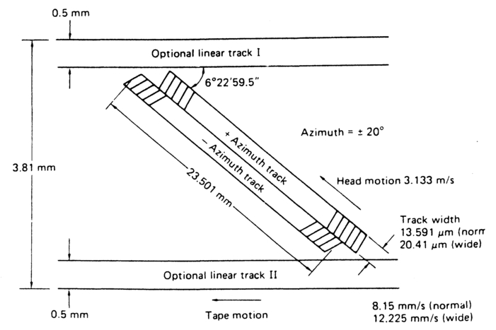
Figure 4.25 Azimuth recording employed in R-DAT results in the natural forming of 'track pairs'.
The matter of incorporating IEC timecode into the format was not easy. The frame rate of R-DAT is not locked to an external clock in domestic models, and it differs from the frame rate of NTSC and PAL television systems and their non-composite derivatives (25 Hz and 29.97 Hz approximately). As a result traditional IEC cannot fit directly into one frame of R-DAT. To overcome this problem, incoming timecode is reprocessed to allow one 80-bit timecode word to be recorded per R-DAT frame. It is recorded in the sub-code areas, together with information regarding the offset between the two frame times. The following section will describe how this is done.
Timecode in the R-DAT system
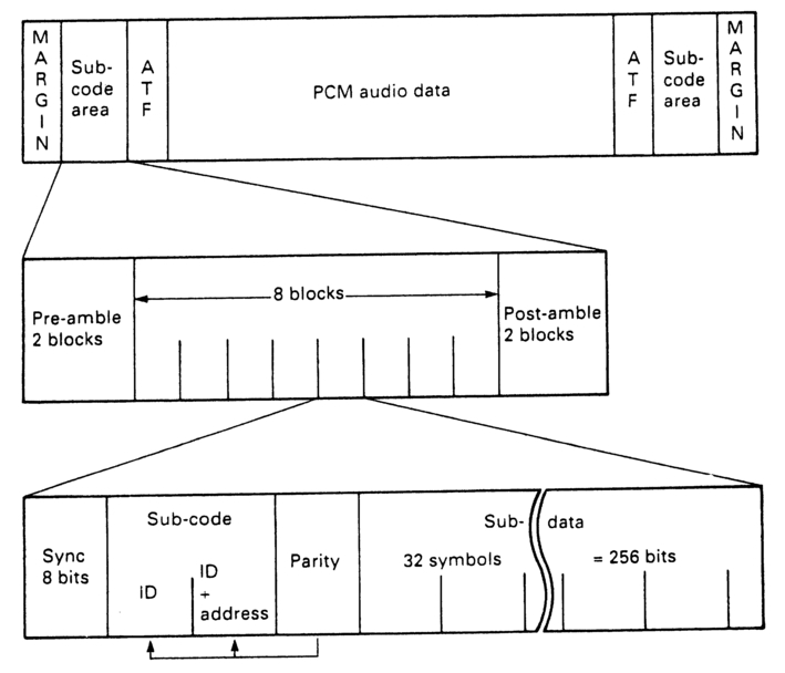
Figure 4.26 The sub-data areas carry 8 blocks of data. Each block contains 256 bits. These are grouped into 32 8-bit symbols.
As Figure 4.26 shows, each sub-code area of an R-DAT track is divided into eight blocks, with an additional two blocks at each end forming pre-and post-ambles. Each block is divided into 36 byte-sized symbols. The first four of these symbols contain synchronizing and sub-data identification information, together with parity checking bits. The remaining 32 symbols are divided into four packs of eight symbols, with each symbol containing 8 bits. There are thus 64 bits per pack, with the first four bits in each pack (the 'item area') defining its content. One of these packs contains the IEC time (but not user bit) information in a form known as 'pro-R time'. The make-up of each pro-R time pack, illustrated in Figure 4.27, is as follows:

Figure 4.27 The Pro-R time pack. It contains information about sampling frequency, frame rate and timecode type. Time and control data are carried in PC4-8. An 11-bit timecode marker carries the offset that results from the difference between R-DAT and video or AES/EBU frame rates.
PC-1 bits 4-7 define the pack as containing running time.
PC-1 bits 2 and 3 together with SPI-0 and SPI-1 define the contents as being pro-R time.
PC-2 bits FO and F1 indicate the sampling frequency in use. This information is necessary to calculate the offset between timecode and RDAT frames.
Bits T0-T2 identify the type of timecode (25 frame, drop-frame etc.).
Bits M0-M10 in the rest of PC-2 and all of PC-3 are collectively known as the 'timecode marker'. They provide information to calculate the offset between the timecode and R-DAT frames in terms of cycles of the sampling frequency.
PC-4 bits carry the hours data.
PC-5 bits carry the minutes data.
PC-6 bits carry the seconds data.
PC-7 bits carry the frames data.
PC-8 bits provide parity checks on the pack.
There are various methods of converting time data from IEC to R-DAT form. One of the simplest to implement is by means of a look-up table.
The timecode marker (TCM)
Because the frame rate of IEC timecode is slower than the frame rate of the R-DAT format, the time and R-DAT frames will cycle through, only occasionally coming into coincidence. If the R-DAT recorder is locked to the same source as the incoming timecode, the offset, though varying, will be predictable. If they are not locked together, or if one (or both) is giving an unstable output, then the offset will be unpredictable and will have to be calculated for each frame. Figure 4.28 illustrates. The nominal ratios between R-DAT frame rate and those of various other media are given in Table 4.2. Although this table shows simple ratios, it must be remembered that these will only be precise if the R-DAT machine and the video camera are locked to a common reference signal.
To calculate the TCM, the IEC time address word is converted into its equivalent R-DAT time frame, perhaps by means of a look-up table. The
Table 4.2 There are simple ratios between R-DAT, 525/60, 625/50 and SMTE film frame rates.
| R-DAT frame rate is 33.33 Hz | ||
| Time Code | Ratio | |
| Type | Time Code : R-DAT | |
| SMPTE | 29.97 Hz | 900:1001 |
| 30 Hz | 9:10 | |
| EBU | 25 Hz | 3:4 |
| Film | 24 Hz | 18:25 |
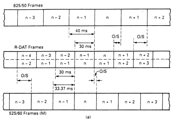

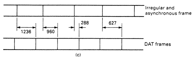
Figure 4.28 (a) In both 625/50 and 525/60 systems the timecode frame duration is longer than the R-DAT frame, (b) When the system is synchronous the time offset is predictable and can be calculated directly from the previous timecode market, (c) When the system has non-synchronous or unstable frame rates the offset cannot be predicted but must be individually calculated.
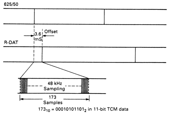
Figure 4.29 The TCM carries, in digital form, the number of samples occurring during the offset between R-DAT frame and incoming timecode frame. For this reason the Pro-R pack must contain sampling rate information.
difference in the start times of the IEC frame and its equivalent R-DAT frame obtained from this table provides an offset, 'or'. There will usually be a difference in time between the start of the R-DAT frame in the look-up table and the actual R-DAT frame 'on'. The difference between the two (on—or) gives a time difference 't' between the reference DAT frame and the actual DAT frame. This time is divided by the periodic time of the master clock (its frequency will be that of the sampling frequency, hence the need to know it). The TCM is the number of clock count obtained. The TCM is converted into digital form and recorded as bits M0-M10 within the pack. Consequently the theoretical resolution of this system is sample accurate (cf LTC which can only be bit accurate — 1/80 LTC wordlength). Figure 4.29 illustrates the process for 625/50 code and a sampling frequency of 48 kHz.
The timecode embedded within the AES/EBU digital interface signal may also be encoded within the time data pack. Bits SPI-0 and SPI-1 flag this condition. The AES/EBU code is placed in packs PC-4-PC-7, MSB in PC-4. PC-8 is for error detection. Figure 4.30 illustrates.
The user bits found within traditional timecode are incorporated in similar manner in a pack situated within a block of sub-data at the other end of the track pair.
Appendix 3 gives details of the R-DAT sub-codes and the formulae used to convert between the different timecodes.
R-DAT timecode in shuttle
Azimuth recording techniques, coupled with the relatively short recorded track lengths of R-DAT, make it possible to read pro-R time in shuttle, as Figure 4.31 illustrates.
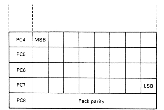
Figure 4.30 PC4-8 carry a 32-bit single code word when recording AES/EBU timecode (ProDIO code).
DASH and Prodigi
Both these formats provide a number of digital linear multi-track options. DASH provides up to 24 digital audio channels plus two auxiliary analogue channels and timecode. A control track looks after tape speed stability. Prodigi provides up to 32 digital audio tracks together with two digital auxiliary audio channels and timecode. There is no control track as the clock signals are embedded within the digital audio channels in the form of sync words. Figure 4.32 illustrates a representative footprint of the two formats.
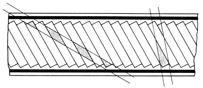
Figure 4.31 R-DAT permits replay of timecode in shuttle because an individual head will not replay track with the inappropriate azimuth, and because the individual data blocks are short and carry idents.
The Prodigi tape must be formatted prior to recording programme material unless all audio tracks are to be recorded simultaneously. This is because the error correction strategy employed calculates checkwords from data across all tracks. Formatting is done by putting the machine into record on all tracks with zero input on all channels. Formatting also provides an opportunity to record timecode.
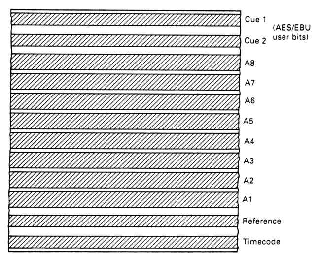
Figure 4.32 A typical DASH footprint.
The DASH format has separate digital audio and timecode/analogue headstacks. The Prodigi records all data, including timecode, on the same headstack, so an advance replay head is provided for 'punch-ins' (Figure 4.33 illustrates). Both formats support the AES/EBU digital audio interface.

Figure 4.33 Prodigi provides an advance play head to permit de-multiplexing of words across the tracks for drop-ins, etc.
It is important, if the machines are to be used in audio/video postproduction, that all recording (and formatting), as well as replay, are undertaken with the machine locked to reference syncs (not a synchronizer).
Nagra-D
This four-channel digital audio field recorder employs 1/4 in tape, records digital audio data as a series of helical tracks, and has an analogue cue audio track as well as control and timecode tracks (Figure 4.34). Standard IEC longitudinal timecode is recorded. The timecode interconnection on the Nagra-D (and for that matter on the analogue Nagra IV-S TC) is via a five-pin 'Lemo' connector. Pin 1 is common (chassis), pins 2 and 3 are for symmetrical timecode in, pin 4 is not connected and pin 5 carries reprocessed timecode out. Figure 4.35 illustrates the pinout. The Nagra-D also has the facility to replay timecode synchonously at a different frame rate from that recorded. So, for example, if timecode has been accidentally recorded at 24 frames/s, it can be replayed as 29.97 frames/sec code while the accompanying audio still replays synchronously with video. The Nagra-D format also allows several machines to be locked together in replay while maintaining accuracy of synchronization to within one audio sample.
1/4in centre-track analogue audio
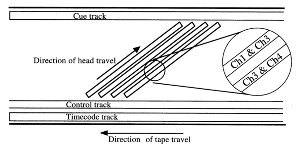
Figure 4.34 The Nagra D tape format incorporates a traditional longitudinal timecode track.
There are two track-width options for two-track analogue audiotape machines, NAB and CCIR. The NAB option has narrower track widths, with a wider guardband between them than with the CCIR standard, so can accommodate a longitudinal timecode track between them with minimal prospect of crosstalk. The LTC signal is recorded along a 0.38 mm wide track in the centre of a 2.0 mm wide band in the centre of the tape, as Figure 4.36 illustrates. The peak-to-peak level should be 6 ± 3 dB below peak-to-peak maximum audio level. Rise and fall times, and overshoot, are those specified in Appendix 2. The code should be recorded with a time constant of 0 Hz (i.e. no equalization), and without noise reduction, these requirements being intended to ensure that minimal phase distortion occurs. Crosstalk from timecode to audio should be better than 80 dB below maximum audio level. Crosstalk from audio to timecode between 40 Hz and 16 kHz should be better than 25 dB below timecode level. Input and output levels should be between 1 and 4 volts peak-to-peak. Input impedance should be greater than 5 kω; output impedance should be less than 40 ω.
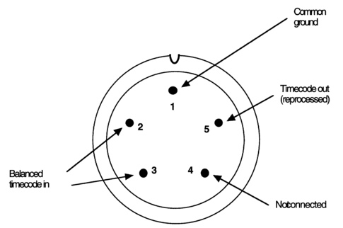
Figure 4.35 The Nagra D accepts IEC timecode in as a blanced signal. The timecode out is reprocessed.

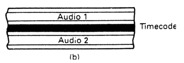
Figure 4.36 Timecode can be recorded in the centre of a two track analogue tape if sufficiently wide guard bands are provided to minimize crosstalk.
Although video machines record and replay audio off the same head (a condition necessary to maintain sync with the picture), audio machines are not so constrained, so can have separate head stacks optimized for their particular function. The manufacturer, therefore, has to consider how the timecode heads will be arranged. Will there be a common write/ read head, or will separate heads be provided? Will the timecode heads be incorporated into the audio headstacks or will they be placed upstream? However the manufacturer arranges things, the timecode address on tape must correspond to the audio material recorded physically alongside it. If the timecode heads are offset from the audio heads, the manufacturer will provide internal compensation for this offset, and may also provide a warning if this offset is in error.
Analogue audio machines lift the tape away from the heads during shuttle, and there are no control tracks to keep account of elapsed time. Instead, they have tachometer pulses, derived from transducers attached to a rotating idler. These pulses are arbitrary in their time spacing, being dependent on the effective diameter of the idler as well as the speed of the tape. They will give an indication of which direction the tape is moving. They may be presented to the outside world in a variety of forms including bi-directional pulses and frequency shift keying. It is important that any synchronizer can understand the particular form in which the tacho pulses will arrive, and the distance travelled (and hence time elapsed) by the tape. If this cannot be done then the audio machine will have to keep slowing down to examine the time addresses. This will make the location of sequences spaced apart on the tape exceedingly tedious. A number of synchronizers on the market will either learn the tacho pulse details automatically, or can be programmed to recognize specific machines by the installation of software.
The Nagra IV-S TC
This 1/4in centre-track timecode machine has a separate pull-out timecode board, situated under the main chassis. It cannot be easily accessed while the machine is in its carry-on case, and is easily damaged if not pushed fully home before the machine is put back into its case. It has extensive timecode facilities, accessed via multi-function key pads, which are outlined in Appendix 10.
Timecode facilities are accessed via a 5-pin 'Lemo' connector, and there are a couple of options available. On both options pin 1 is common connection to chassis. One option provides for symmetrical (balanced) timecode in on pins 2 and 3. The other option provides for unbalanced longitudinal (IEC) timecode in on pin 2, with pin 3 carrying Aaton timecode in/out on pin 3. On both options pin 4 (TC play) carries the unregenerated (differentiated) timecode signal when in playback. Pin 5 (TC out) carries the timecode generator output while recording and in 'Test', and provides regenerated timecode out when in playback. Figure 4.37 illustrates the differences in pinouts.
The energy for the timecode generator is supplied across a large (1 F) capacitor. This will power the timecode circuits for about 2 minutes when internal batteries are changed. It takes about 50 seconds to charge up when the Nagra is first switched on, or after storage without batteries. Until it has charged no timecode functions can be guaranteed.
Audio analogue multi-track
Timecode must be placed on the highest numbered track of a multi-track machine. Noise reduction should not be employed in order to minimize the possibility of phase distortion. The next highest track number should be left spare, and timecode should be recorded at -10 VU. These two precautions are intended to minimize crosstalk. It is important to ensure that timecode is replayed from the correct headstack. The arguments that apply to tachometer pulses on Vain machines apply to 2in multi-track as well. Consideration should be given to incorporating dedicated electronics for the timecode track, to enable reading and reprocessing on replay.
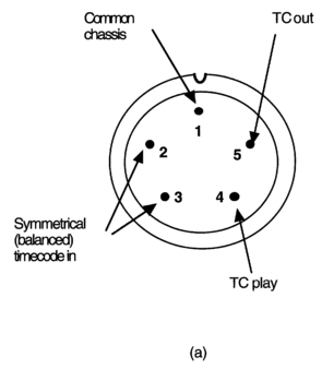
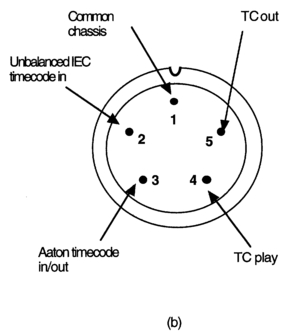
Figure 4.37 The Nagra IV-STC has the option of two versions. In (a) IEC timecode is accepted as a balanced input on pins 2 and 3. In (b) IEC is accepted as an unbalanced input on pin 2, with Aaton timecode in/out on pin 3. In both cases pin 1 is common. Both versions deliver reprocessed timecode out on pin 5 (off-tape in play, tc generator in other powered models), and unprocessed off-tape timecode out on pin 4.
Recording levels
The IEC now specifies the tracks and recording levels for time-and-control codes recorded in formats used with broadcast standard VCRs. These are summarized in Table 4.3, together with details of the relevant IEC publications and sections.
Table 4.3 IEC specifications for timecode tracks and levels.
| Format | IEC Publication and Section | Time-code track | Recording Level* | Notes |
| Transverse-track | 347 [4] Section 4.5 | Cue track | 600-800 nWb/m p-p | 1 |
| Format B | 602 [5], Amendment 1, Section 7.4.3 | Audio track 3 | 720±70 nWb/m p-p | 2 |
| Format C | 558 [6], Amendment 1, Section 8.5.3 | Audio track 3 | => 186 nWb/m p-p | |
| Betacam SP | 961 [7] Section 13 | Dedicated time-code track | 500 nWb/m rms | 3 |
| Mil | 1118 [8] Section 5.4 | Dedicated time-code track | 250±50 nWb/m p-p | |
| D1 | 1016 [9] Section 35 | Dedicated time-code track | 185±20 nWb/m rms | |
| D2 | 1709 [10] Section 9.5 | Dedicated time-code track | 500±20 nWb/m p-p | |
| D3 | [11] Section 39 | Dedicated time-code track | 250±20 nWb/m p-p | |
| Analogue multitrack audio | 94-6 [12] | Audio track having the highest number | Not standardized | 4 |
Notes:
* Recording levels are expressed as the rms or peak-to-peak magnetic short-circuit flux level, per metre of record track width.
1. The transverse-track format is obsolete and is no longer recommended for programme exchanges.
2. A recording level of 720 nWb/ m p-p corresponds to 254 nWb/m rms, for a sinusoidal signal.
3. The recording level shall be sufficient to ensure full saturation of the magnetic domains.
4. The audio track adjacent to the track carrying the time-code should preferably remain un-recorded. The recording level is chosen to give reliable time-code reading at speeds which are not close to zero, but should be low enough to avoid cross-talk into the audio tracks.