
Chapter 3
The timecode word
As this edition went to press, the EBU/SMPTE Task Force for Harmonized Standards for the Exchange of Programme Material as Bitstreams issued its final report. It identified the following requirements regarding timecode:
Timecode standard should be the revised SMPTE12M (still under revision at this time).
The original quadruplex cue track
When practical videotape recorders were first being developed by the Ampex Corporation, a narrow-bandwidth, voice-quality audio track was incorporated onto the then current 2-inch VTRs in addition to the high-quality audio track. Although designed principally to record such material as talkback, the bandwidth of this longitudinal track allowed a 2400 baud (bits/second) digital signal to be recorded and replayed. At a video frame rate of 30 fps, this corresponds to a density of 80 bits per frame. The bit rate was limited by the need to read the signal while the tape was spooling.
The development of a longitudinal timecode (LTC) word
An 80-bit word will permit 280 (equivalent to approximately 1024) combinations of information to be incorporated in each frame. This is far in excess of that required to record hours, minutes, seconds and frames (approx. 106 or 220). Longitudinal timecode requires 26 bits to record a frame-accurate time address, so additional data could be incorporated. This has been fortunate, as later developments have been able to use the spare capacity.
The biphase mark code
Although binary number systems lend themselves readily to processing by electronic circuitry, we saw in Chapter 1 that the output voltage of a magnetic record/replay device depends on the derivative (rate of change) of the recorded magnetic flux on replay rather than the absolute flux level, so runs of consecutive digits without any transitions in flux on replay cannot be decoded.
In Chapter 2 we saw that RZ, NRZ and FSK codes are all unsuitable for longitudinal timecode. To make the code self-clocking, while exploiting the full potential amplitude for code pulse transitions, and to make it immune to accidental polarity reversals, the clocking information is incorporated into the code itself, using the pulse edges rather than the instantaneous code polarity to carry the digital information.
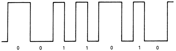
Figure 3.1 Biphase mark systems are independent of signal polarity, are self-clocking and d.c. free.
A digital zero is represented by the absence of any transition in the middle of the space between clock pulse edges, a digital one is represented by such a transition, positive- or negative-going as appropriate. The start of each bit space is marked by a transition, again positive- or negative-going as appropriate (Figure 3.1). Decoders in timecode readers enable the signal to be read over a wide range of replay speeds. The d.c. value of the code varies very little, simplifying the design of associated electronics. The ability to detect sharp pulse edges for timing accuracy will require a bandwidth capable of passing at least the 3rd harmonic of the fundamental frequencies.
User bits
The spare capacity permits timecode users to incorporate digital information of their own, grouped in the form of 4-bit words. These binary groups are commonly called 'user bits'. They can be used for a variety of purposes such as identifying take/shot numbers, calendar date, client code etc. The only limitation to their use is the ingenuity of the user. Several versions of the standard code have the option of putting a date into these groups, others incorporate alphanumeric character codes (ASCII code), and yet others can record details of a film shoot, such as scene, take and roll numbers.
There are eight of these groups per frame, so up to 8 x 25 = 200 4-bit blocks of information can be sent per second in a 625/50 system. Eight bits (7 data, 1 parity) are required for each alphanumeric character, so four 8-bit characters can be sent per video frame.
The form of the LTC word
When applied to video- and audiotape recording, the code is continuous. Each codeword starts at the clock edge immediately before the first bit (bit 0). The bits are uniformly spaced, and there are eighty bits per frame. The resulting bit rate varies between 1920 bits/second (for 24 fps applications) and 2400 bits/second (for 30 fps). Used as a time and control code for television recorders, the previous EBU and SMPTE standards have been incorporated into the IEC standard 421:1986 (amended in 1990). Within the EBU this has been implemented as EBU standard N12:1994. In the UK this has been implemented as BS 6865:1987 (amended 1993) and in the USA as SMPTE 12M:1994 (which also includes a specification for timecode for use with High Definition TV having 1125 lines/frame at 60 fps). This book will refer to the code as IEC timecode, and will highlight the difference in its implementation by the EBU and the SMPTE in terms of 625/50, 525/60 and 1125/60 versions of the code. The implementation of the SMPTE 24 fps code for film use will be dealt with at the end of this chapter, and again separately in Chapter 5.
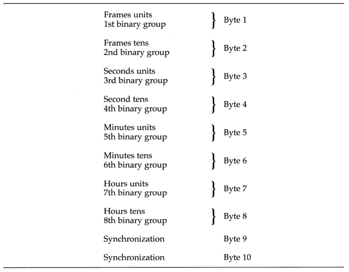
Figure 3.2 The LTC word comprises 10 bytes. Eight of these carry time and control data, two carry synchronization and direction information.
LTC byte arrangement
In both versions of the code, the longitudinal timecode word can be thought of as comprising 8 bytes (64 bits) of data followed by 2 bytes (16 bits) of synchronizing information (Figure 3.2), making 80 bits in all, numbered 0-79. Twenty-six of the available bits are used to indicate the coded time down to the nearest frame. The time information is distributed throughout the length of the complete word.
Each data byte is divided into two 4-bit nibbles; 2, 3 or 4 bits of time data in the first nibble, and 4 bits of user data in the second. Bytes 2, 4, 6 and 8 contain additional information in the first nibble of each byte. This information differs slightly between the 625/50 and 525/60 versions of the code. The arrangement of the data in bytes, and the placing of the user information in the second nibble of each byte permits easy implementation of control data such as edit decision list information for an edit controller, shot listing on location, and the carrying of additional timecodes, enabling the video post-production of film. As the binary groups are arranged in groups of four bits, they can each be used to represent a hexadecimal number, or can be combined in pairs to carry 4 International Characters (ASCII, etc.) per timecode frame. In both the 625/ 50 and 525/60 versions of the code the time and user data occupy the same places within the complete word, as Figure 3.3 illustrates.
The assignment of the time bits can be summarized as follows:
| Pictures | Units: | Bits 0-3: | arranged 1, 2, 4, 8: | count 0-9 |
| Tens: | Bits 8-9: | arranged 1, 2: | count 0-2 | |
| Seconds | Units: | Bits 16-19: | arranged 1, 2, 4, 8: | count 0-9 |
| Tens: | Bits 24-26: | arranged 1, 2, 4: | count 0-5 | |
| Minutes | Units: | Bits 32-35: | arranged 1, 2, 4, 8: | count 0-9 |
| Tens: | Bits 40-42: | arranged 1, 2, 4: | count 0-5 | |
| Hours | Units: | Bits 48-51: | arranged 1, 2, 4, 8: | count 0-9 |
| Tens: | Bits 56-57: | arranged 1, 2: | count 0-2 |
A twenty-four-hour clock is used. The first frame of the day is reckoned as 00h 00m 00s 0lf (00h 00m 00s 00f is reckoned as midnight at the end of the day — the count does not go up to 24h 00m 00s 00f).
Bits 64 to 79 make up that part of the overall timecode word called the 'synchronizing word'. This consists of a pair of 0s at its start, a 0 and 1 at its end, and a chain of 12 ls in between. The purpose of the synchronizing word is two-fold: it serves to indicate clearly the end of one word and the start of the next, since nowhere else in the word can twelve successive ones exist. It also indicates whether the tape is being played forwards or backwards since the pair of 0s will come first if the tape is being moved forwards, and a 1 followed by a 0 will indicate the tape being moved in reverse (Figure 3.4).
In both 625/50 and 525/60 versions of the code, bits 10, 11, 27, 43, 58 and 59 carry no time or user data. The implementation of these additional

Figure 3.3 The 625/50 and 525/60 LTC words compared.

data bits varies between the two versions of the code, and will be dealt with separately.
The detail of the 625/50 LTC
The implementation of the additional data bits is as follows.
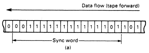
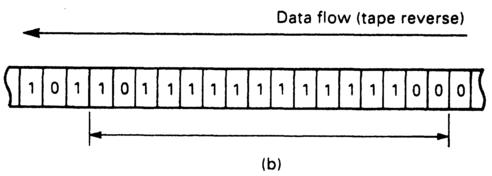
Figure 3.4 The 2 bits at either end of the synchronization word are not symmetrical. This enables the direction of tape motion to be determined.
Bit 10
Unassigned. The use of this bit is reserved by the IEC. Until it is assigned it must be a permanent zero.
Bit 11
This is the colour frame flag bit. Its purpose is to indicate whether or not the timecode has a specific relationship to the phase of the colour subcarrier. As discussed in Chapter 1, the colour sub-carrier changes phase with respect to the line sync pulse every line in order to minimize patterning, and it takes eight fields, four complete frames in PAL systems, to return to its original phase at the beginning of the frame (the first of the broad pulses in the vertical interval in 625/50 systems). In the SECAM system the sequence is 2 frames (4 fields) long. In both these systems the colour sub-carrier, extrapolated back to the leading edge of the first line pulse of the first field of the day shall be crossing zero and going positive (Figure 3.5). The international standard is that the first frame of the day will be frame 1, fields 1 and 2. To achieve this relationship the timecode generator needs to be locked to the sync pulse generator generating the colour sub-carrier. When the relationship is correct, bit 11 in the timecode word is set to digital 1. The details are covered in Appendix 1.
Bits 27, 43 and 58
We have already seen that the binary groups can be set to carry additional information such as the eight-bit character set specified in ISO 646 and ISO 2022. Prior to 1993, bit 58 was unassigned, and bits 27 and 43 flagged the use of the binary groups to carry these characters. In 1993, however, the SMPTE proposed the use of bits 27, 43 and 58 to flag the extended use of the binary groups in a 'page-line index' through the use of time multiplexing the data over several timecode words. This extended use permits the carrying of an additional timecode, control codes, text and production information. A description of the page-line index is given in Appendix 5, the detail being given in SMPTE 262M. The following truth table applies to these bits in 625/25 systems:
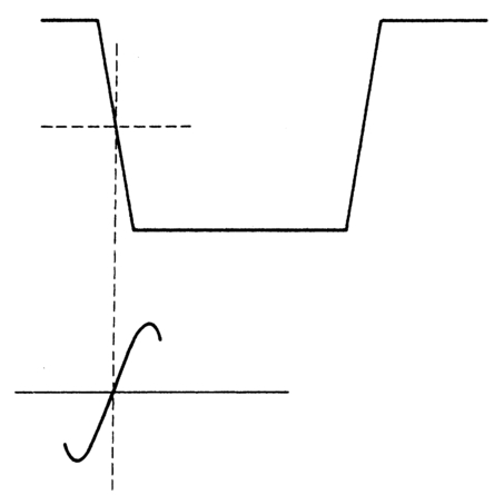
Figure 3.5 At the start of the first field of the day, the colour sub-carrier is crossing zero, going positive, at the same time as the leading edge of the first sync pulse is at half amplitude.
| Bit 27 | Bit 43 | Bit 58 | |
| BGFO | BGF2 | BGF1 | |
| Character set unspecified | 0 | 0 | 0 |
| 8-bit set to ISO 646 and ISO 2022 | 1 | 0 | 0 |
| Page/line index | 1 | 1 | 0 |
All other states are unassigned and should be set to zero as their use is reserved.
Figure 3.6 illustrates the arrangement of the binary groups for the ISO character sets. Groups 1/2, 3/4, 5/6, 7/8 each combine to define one ISO character.
The basic ISO 646 character set defines two 7-bit Latin code tables:
- Basic code table with all alphanumeric characters, punctuation marks, and control functions, together with ten free codes for national use and some limited graphics.
- International reference version (IRV), having the national characters filled, and a choice made where more than one graphic symbol is shown in the basic table.
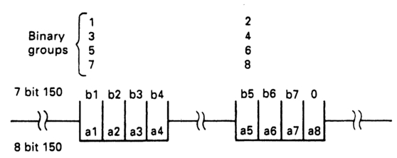
Figure 3.6 The eight 4-bit user groups may be combined to carry four alphanumeric characters to either ISO 646 or ISO 2022 standards.
The ISO 2022 gives code extension techniques by converting the code to 8-bit, based on the ISO 646 'Escape' command. This gives access to a library of centrally-registered characters such as ASCII and Teletext. The registration is done by the French National Standardization Office (AFNOR).
If bits 27 and 43 are set to 0 and 1 respectively, this indicates the use of the binary groups for carrying information when shooting with film. Although the SMPTE has an accepted standard, at the time of writing it has not been adopted in Europe.
Bit 59
This is the biphase mark correction bit. There are many occasions during post-production when non-contiguous sections of code (that is, code recorded as a continuous stripe, but where the time addresses do not increment up one at a time) may have to be joined together. This will happen when programme material comes from different parts of the master tape(s), or when Time of Day code has been recorded. When this occurs there is the possibility of losing the clock edge at the join, causing the timecode readers and synchronizers to miscount.
The following example explains the principle. Consider a 5-bit word containing 4 bits of data plus a spare bit. If we joined together two such words, the first containing 0101, with the spare bit set to 1, the second containing 0111, with the spare bit set to 1, the two words will join together in such a manner as to preserve the clock edges at the joint (Figure 3.7a). However, should the first word contain an odd number of 0s, for example 1110, with the spare bit set to 1, then the clock edge will be lost at the join (Figure 3.7b).
The way round the problem is to ensure every word contains an even number of 0s (and hence an even number of 1s). Bit 59 is put in a state to make bits 0 to 79 of the timecode word contain an even number of 0s. At the time of writing the biphase mark correction bit is not a requirement for tape interchange.
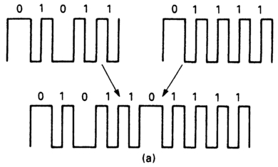

Figure 3.7 (a) A word ending with a positive-going transition will join the next word unambiguously. (b) If the word ends with a negative-going edge the transition will be lost.
Codeword timing
Synchronization of the codeword with the video signal is necessary if the codeword is to identify accurately an individual video frame. For the 625/50 version of the code, the start of the word (the half-amplitude point of the leading edge of bit 0) shall occur within the period of the field (broad) pulses at the start of the frame with which the codeword is associated (Figure 3.8).
The detail of the 525/60 LTC
Although the 525/60 code runs at 30 fps or so for video, the time data, synchronization and binary groups bits are arranged in exactly the same way as the 625/60 version. The remaining bits differ in their application.
Bit 10
This is the drop frame flag. It is used to indicate whether the frame rate is exactly 30 fps or if it is approximately 29.97 fps. It is set to '1' if a 29.97 (drop frame) rate is being used.
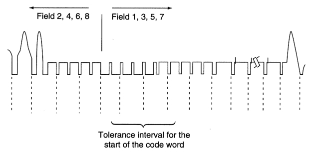
Figure 3.8 The LTC word must start within the first 2 lines of the frame in 625/50 systems.
Bit 11
This is the colour frame flag bit. The NTSC system utilizes a 4-field colour sequence, the frames being labelled 'A' and 'B'. If an even timecode address identifies an 'A' frame, and an odd address a 'B' frame then this bit is set to '1'. Note that to maintain the sequence through an edit point, an even code address must be followed by an odd one. Drop frame working permits this because two consecutive frames are dropped at the start of each minute (except each tenth minute), and not one frame each 30 seconds.
Bit 27
This is the biphase mark correction bit. It performs exactly the same function as its counterpart in the 625/50 version of the code, so the detail will not be repeated here. One point worthy of note, however, is that the original version of this code did not provide this facility, so this bit was set to permanent zero. As a result some elderly NTSC editing systems cannot read timecode correctly with biphase mark correction in operation. Note that its position in the word differs from its 625/50 counterpart.
Bits 43 (BGF0), 58 (BGF1) and 59 (BGF2)
These are the binary group flags. They perform similar functions to their counterparts in the 625/50 version of the code, though their positions in the word differ from their 625/50 counterparts. There are SMPTE standards and recommendations for the use of the binary groups with film. These are covered in Chapter 5. These flags signal the various uses.
Codeword timing
In the 525/60 version of the code, the start of the word (the half-amplitude point of the leading edge of bit zero) shall coincide with the start of line seven of the frame with which the codeword is associated, plus or minus one line (Figure 3,9). Note that the specification for the start of a field differs between 625/50 and 525/60 systems.
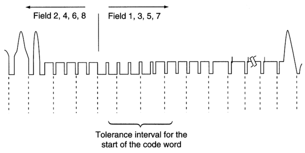
Figure 3.9 The LTC word must start within lines 6/7 of the frame in 525/60 systems.
The requirement for vertical interval timecode (VITC)
Longitudinal timecode has several shortcomings when used to edit videotape. Chief among these are the impossibility of reading it when the tape is stationary or when the tape is being jogged slowly to find an exact edit point. As a number of lines in the field interval are not used to carry pictures, it is possible to utilize some of them to carry timecode. Though some may carry chrominance information, test signals or teletext information, enough are available, with careful choice of line, to carry timecode during the editing stages of production. As the active line period is approximately 52 μs long in both 625/50 and 525/60 systems it is possible to incorporate a 90-bit code into one or more of these spare lines without exceeding the bandwidth limit (Figure 3.10).
The form of the VITC word
The VITC word is ninety bits long (bits 0-89). It takes the form of 8 bytes of time and user data, each byte (including the first) being preceded by a pair of synchronizing pulses. The eight data bytes are followed by 1 byte of cyclic redundancy check code (Figure 3.11). It is incorporated within the vertical interval in each field of the video signal, with a margin of a few lines before the active frame. There are differences in the lines specified as valid for the code between 625/50 and 525/60 versions, and these will be dealt with separately. It has traditionally been repeated twice within each field to guard against dropout. Since dropout may have a duration of more than one line, VITC is usually recorded on two nonadjacent lines with an intervening blank line between them. At the time of writing there is no agreed standard as to which lines VITC should occupy Recent developments in timecode applications, and increasing pressure on the use of the vertical interval for additional signals, have led manufacturers to provide the options that include VITC on 1 line per field, and VITC repeated in a block over several consecutive lines. Since the code is incorporated within each field of the video frame, it is possible to include information within the codeword to identify the field.
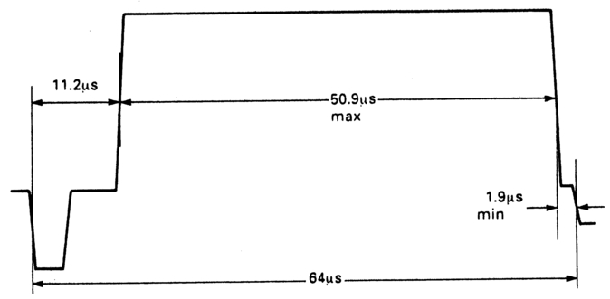
Figure 3.10 A 90-bit word may be incorporated within the active line period without exceeding the bandwidth limits.
The vertical interval version of timecode need not be self-clocking, since the reading speed of a videotape machine scanning head is virtually independent of tape speed within certain limits. The code is therefore not biphase, and a simple 'non return to zero' code is used. There is no synchronizing word because, being incorporated within a small part of a complete video field, the data are not presented as a continuous bit stream. As the video heads will always read the video tracks in the same direction, there is no need to indicate the direction in which the time address data are being presented.
A digital 1 is represented by a positive voltage substantially above blanking level (its actual level differs between the 625/50 and 525/60 versions). A digital 0 is repesented by a voltage at blanking level.
As the codeword occupies approximately 50 μs of the active video line, the data rate is 1.8 megabits/second. If the bits presented are a sequence of 1s and 0s, this rate of data represents a fundamental frequency of 0.9 MHz. To preserve the steep pulse edges required for timing accuracy, the third harmonic must be present. This implies a bandwidth requirement of at least 2.7 MHz. Not all industrial-grade (or domestic!) video recorders will support this.
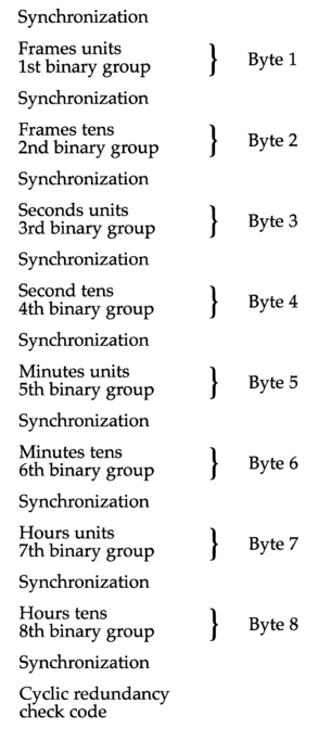
Figure 3.11 The VITC word comprises 8 data bytes containing time and control information, followed by a single byte for error detection. Each byte is preceded by two synchronizing bits.
In both 625/50 and 525/60 versions of the code, the time and user data occupy the same places within the complete word, as Figure 3.12 (pp. 44-45) illustrates, though the positions of the flag bits can vary, as with LTC,
The cyclic redundancy check bits
Parity checking is unsuitable for videotape applications because of the high risk of tape dropout. In place of the now unnecessary synchronizing word, the VITC word contains 8 bits of error protection in the form of a cyclic redundancy check word, bits 82-89. The generating polynomial is G(x) = x8 + 1. There is no automatic error correction within the word but, as we see later, other techniques are employed to improve the immunity of the system to errors. As codeword is repeated several times per frame there is a high probability of the data being recovered without error.
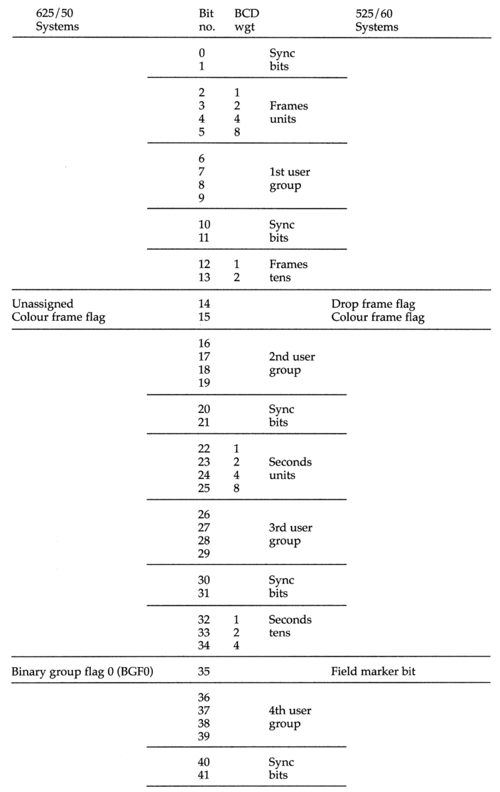
Figure 3.12 The 625/50 and 525/60 VITC words compared.
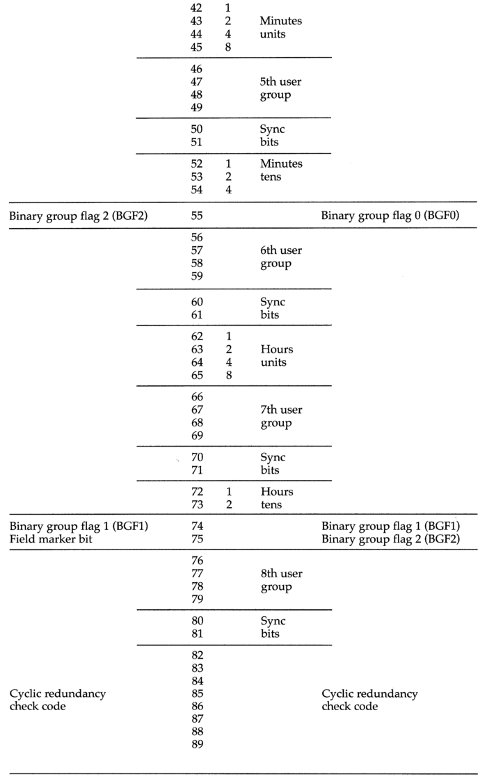
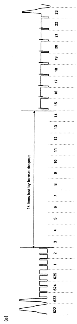

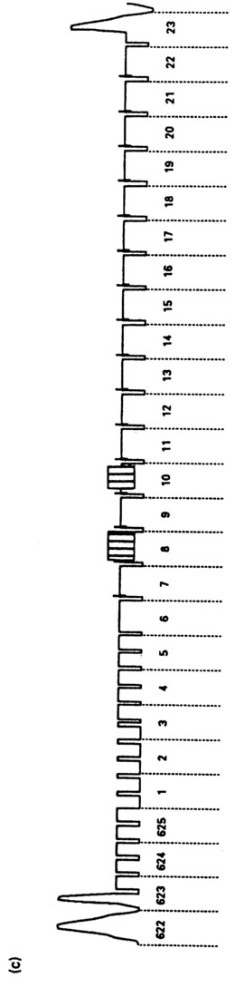
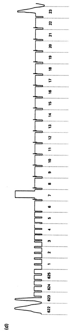
Figure 3.13 (a) In C-format VTRs, 14 lines are lost by format dropout, (b) Test signals may be present on lines 17 and 18. (c) VISC may be on lines 8 or 10 in component recorders, (d) Line 7 may contain the colour frame flag.
The detail of the 625/50 VITC
Position within the field interval
In its 625/50 version, the VITC word is placed no earlier than line 6 (319), and no later than line 22 (335). However, there are constraints about which lines are most suitable, since the field interval is often used for processes other than field synchronization. In the SECAM system lines 7 to 15 (320 to 328) are occupied by field identification signals, so should be avoided. To avoid possible reading errors which may arise in the presence of skew, a margin should be allowed between the video head switching points and the recorded VITC word. For similar reasons an adequate margin should be used if dynamic tracking (DT or AST) heads are employed. Some lines may be used for other signals. C-format VTR machines suffer from format dropout (see Chapter 4), and 12 lines in the vertical interval will not be recorded unless the sync head option is employed. Component Analogue tape recorders put VISC on line 8 or 10 (321 or 323), and lines 17 and 18 may be used for engineering test signals. Figure 3.13 illustrates the possibilities and limitations. Common practice involves placing the VITC word on lines 19 and 21 in its 625/50 version, and most VITC generators and readers are factory-set at these lines.
Position within the line
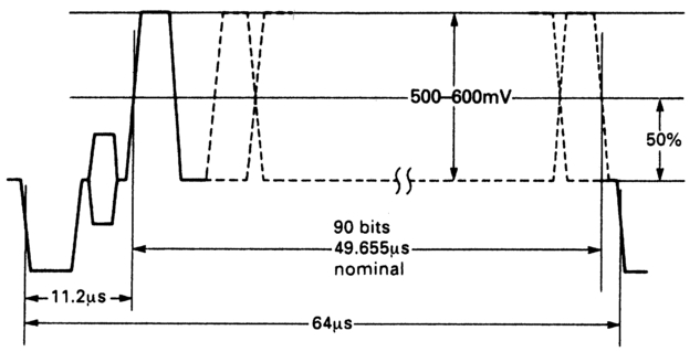
Figure 3.14 The position of the VITC word within the 625/50 line.
The word occupies 49.655 μs (nominally), being generated at 115 x Fh ±2% bits/s, where Fh is the line repetition frequency. Hence the nominal bit rate is 1.796875 Mbits/s. This is a lower rate than previously specified but the previous bit rate does lie within the new tolerance. The word should start no earlier than 11.2 μs after the start of the line synchronizing pulse, and if the last bit is a '1' it should end no later than 1.9 μs before the leading edge of the synchronizing pulse for the next line. This gives a maximum duration of 50.9 μs available for the codeword. The pulses should be equally spaced. A logical '0' is represented by a level of 0-25 mV, and a logical '1' by a level of 500-600 mV. Figure 3.14 illustrates.
Bit assignment
Synchronizing bit pairs 0,1; 10,11; 20,21; 30,31; 40,41; 50,51; 60,61; 70,71; 80,81
Each of these pairs consists of a fixed '1' followed by a fixed '0'. Their distribution throughout the codeword is necessary because VTR machines suffer small timing errors (called 'velocity errors') along lines, which result in a degree of jitter. Although these errors are dealt with by timebase correctors, the process can also replace the synchronizing pulses, colour bursts and the vertical interval, together with the timecode. If this is the case, it will be necessary to regenerate the code prior to timebase correction, while small timing errors still exist, re-inserting the code after timebase correction (Figure 3.15).
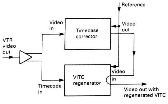
Figure 3.15 A timecode regenerator may be needed if the timebase corrector replaces the whole of the vertical interval.
Bit 14
This is unassigned. The IEC reserves its use. It should be fixed 0 until specified by the IEC.
Bit 15
This is the colour lock flag bit. It is set to logical '1' when the timecode is locked to its associated PAL colour signal in accordance with the 8-field sequence (4-field in SECAM), and the video signal has the preferred subcarrier-to-horizontal phase relationship. Its purpose has been covered in discussion of the 625/50 longitudinal code earlier in this chapter.
Bits 35, 55 and 75
These are the binary group flag bits. The detail has been covered in discussion of the 625/50 longitudinal code earlier in this chapter.
Bit 75
This is the field identification flag bit. VITC has no need of a biphase mark correction bit. The equivalent bit identifies the fields without reference to the field sync pulse sequence. It is set to logical '1' during fields 2, 4, 6 and 8, and to logical '0' during fields 1, 3, 5 and 7 in PAL (fields 2,4 and 1,3 for SECAM).
The detail of the 525/60 VITC
Position in the field
In 525/60 systems the VITC word is placed no earlier than line 10 (273) and no later than line 20 (283). To avoid decoding errors in the presence of skew, a margin should be allowed between the head switching points and the lines used for recording VITC. Some lines may be used for vertical interval test signals (VITS). The C-format VTR has 10 lines of format dropout in the NTSC system.
Position in the line
The word occupies 50.286 μs (nominally), being generated at 115 x Fh±2% bits/s, where Fh is the line repetition frequency. Hence the nominal bit rate is 1.81125 Mbits/s. This is a higher rate than previously specified but the previous bit rate does lie within the new tolerance. The word should start no earlier than 10 μs after the start of the line synchronizing pulse, and if the last bit is a '1' it should end no later than 2 μs before the leading edge of the synchronizing pulse for the next line. This gives a maximum duration of 50.566 μs available for the codeword. The pulses should be equally spaced. A logical '0' is represented by a level of 0-10 IRE, and a logical '1' by a level of 70-90 IRE. Figure 3.16 illustrates.
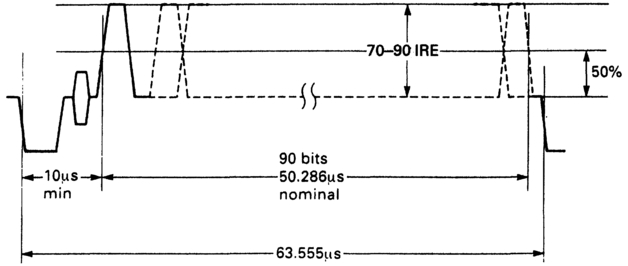
Figure 3.16 The position of the VITC word within the 525/60 line.
Bit assignment
The sync pairs, time and user data bits, and the CRCC bits are identical to the 625/50 version of the code.
Bit 14
This is the drop frame flag (see p. 39).
Bit 15
This is the colour frame flag (see p. 40).
Bit 35
This is the field identifier flag bit. A logical '0' represents fields 1 and 3, in which the first pre-equalizing pulse follows the last line synchronizing pulse by one whole line. A logical '1' represents fields 2 and 4, in which the first pre-equalizing pulse follows the last synchronizing pulse by a half line.
Bits 55, 74 and 75
These are the binary group flag bits (see pp. 36-38).
Comparisons between LTC and VITC in both 625/50 and 525/60 versions
The bit contents of 625/50 LTC and VITC are compared in Figure 3.17 (pp. 52-53). The 525/60 LTC and VITC are compared in Figure 3.18 (pp. 54-55). The technical differences are covered in Appendix 2.
Timecode and MPEG-2
SMPTE Standard 312M specifies the technique for carrying notification of 'splice points' in the MPEG-2 transport stream, Splice points identify events such as a break from network to carry a commercial (ad), or a return to network after carrying a commercial. Programme identifier streams, carried separately from the transport stream, contain tables that provide command and control information for the splicer (the equipment making the switch). These tables can be sent ahead of time, perhaps 8, 5, 4 and 2 seconds in advance; the splicer may be given a preroll warning; or a command may be given to execute the splice at a particular time.
The information is given in a number of tables, and one of these, Table 11, carries SMPTE12M timecode as a 64-bit word. These bits are the time and control bits of VITC, without the synchronizing bit pairs or cyclic redundancy check code, stored LSB first. An LTC timecode source can be used, but the bits must be remapped to conform to VITC standard. At the time of writing, SMPTE12M is being rewritten to provide for time zone, date and clock time reference.
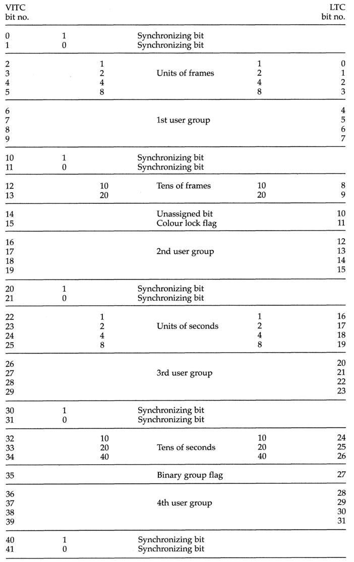
Figure 3.17 The 625/50 VITC and LTC words compared.
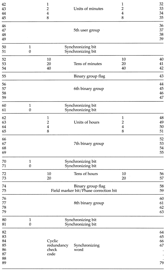

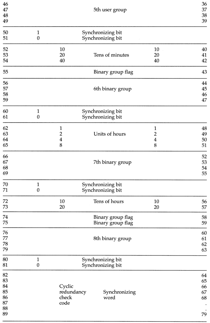
Figure 3.18 The 525/60 VITC and LTC words compared.
The time address and the associated colour TV signal
For purposes of electronic editing of composite television signals, the correct colour sub-carrier field sequence must be maintained across the edit point to avoid picture disturbance. The timebase corrector in a VTR or VCR system achieves this by shifting the start of the active line from the machine designated as 'slave' to bring the sub-carrier in phase with that on the recorder. This shift is a fraction of a sub-carrier cycle and is not noticeable when the cut or mix is between dissimilar pictures. However, cutting between identical pictures (perhaps for the purposes of shortening a sequence, or during an animation sequence) will result in this shift being noticeable.
These problems can be avoided by cutting on the correct frame to avoid the need for a shift in the picture. This can be determined by a timecode sync monitor (Figure 3.19) which displays the relationship on a picture monitor. The sub-carrier-to-sync relationship can be incorporated in the timecode by establishing a standard relationship between time-of-day and the 8- or 4-field sequence. If this relationship is correct, the colour lock flag is set to logical '1'. For this method to work, it is imperative that the relationship be determined at video and timecode generation, and carried through without ambiguity at all stages of production. This will be covered in detail in Chapter 9.
There are various ways by which timecode generators can identify frame 1 in the colour frame sequence. These include examination of the sub-carrier-to-sync relationship, by detecting a marker pulse inserted in line 7 of field 1, or from a flag generated by the SPG. The important point is that the timecode generator must have some form of colour-related synchronizing information if it is to generate colour-framed code. Appendix 1 examines the relationship between timecode and the colour frame sequence in detail.
The 525/60 drop-frame code (M/NTSC)
Timecode locked to a 29.97 fps frame rate (as it must be for later postproduction) will accumulate an error at 0.03 of a frame each second. Over a one-hour period the discrepancy between 'real-time' and 'colour-framed' time addresses will be 108 frames, i.e. 3.6 seconds, the timecode addresses falling behind in real time. To compensate for this, 108 frames have to be dropped every hour to allow the code to catch up with real time. Single frames cannot be dropped because of the need to maintain the 4-field colour frame sequence (colour frame A must be followed by colour frame B and vice versa), so a frame pair is dropped at the start of each minute, except minutes 0, 10, 20, 30, 40 and 50.
(2x60) - (2x6) = 120 - 12 = 108 frames
Figure 3.19 A timecode sync monitor display. Marker pulses on the right-hand edge indicate the field sequence. Markers on the bottom edge indicate S-C/H phase.
The frame count over, say, the end of the eighth minute in the hour will go:
01.08'59"28f
01.08'59"29f
01.09'00"02f
01.09'00"03f etc,
whereas over the end of the ninth minute of the hour the count will go:
01.09'59"2Sf
01.09'59"29f
01.10'00"00f
01.10'00"01f etc,
The dropping of these frames results in a discrepancy between real time and timecode addresses that varies by ± 60 μs over 10 minutes, illustrated in Figure 3.20. The discrepancy accumulates over a period of one minute when, as can be seen, the dropping of two frames slightly overcompensates. This overcompensation increases at the end of each succeeding minute until, at the ninth minute the time address is 60 μs in advance. This accumulated residual error is compensated for by not dropping the first two frames at the start of the 10th minute.
The above process does not exactly compensate for the discrepancies between real time and colour-frame time, because the NTSC frame rate is not exactly 29.97 Hz: it is 29.970 026 17 Hz. This difference results in a long-term residual discrepancy of 0.000 026 17 x 60 x 60 x 24 = 2.261 frames over a 24 hour period, equivalent to 86.4 μs. Good operational practice requires that the timecode generator be reset at regular intervals if long-term errors are not to accumulate. Commercial timecode generators are available which allow the 86 μs discrepancy to be corrected at a time when least disruption to programme making will occur. The correction is made daily, automatically, and at a time programmable by the user

Figure 3.20 The short-term error in drop-frame code varies by ±60 μs over 10 minutes. It is corrected by not dropping a frame at the 10th minute
M/PAL drop-frame code
The frame rate of system M is also approximately 29.97 fps. When this frame rate is combined with the PAL modulation system it is not possible to drop two frame sequences to resolve the colour frame error. Instead, the first four frames (1-4) are dropped from the count at the start of every 2nd minute (even minutes), except for minutes 0, 20 and 40. In this mode LTC bit 10 (bit 14 in the VITC equivalent) is set to '1'. The IEC refers to the drop-frame mode of M/NTSC and M/PAL as Mode 1. The non-drop-frame mode is referred to as Mode 0.
Digital VITC
D-VITC is an 8-bit digital representation of the analogue shape of the 90-bit VITC signal supported by analogue VCRs. It is recorded on lines 14 and 277 of the CCIR 601-2 component (4:2:2) digital video signal, with the option of additional insertion on lines 16 and 279. As it is recorded as a part of the data on the helical video tracks it can be read when the DVCR is either stationary or shuttling at too low a speed for LTC to be read.
CCIR 601-2 codes each video line with alternate data words of colour difference and luminance samples in the sequence Cb Y Cr Y Cb Y Cr Y etc, with a total of 1440 samples per line, clocked at 27 MHz, giving an active line duration of 53.333 jus (nominal). Each active line is preceded by a SAV (start of active line) code and terminated with an EAV (end of active line) code. D-VITC is placed on the luminance (it is not carried in the chrominance) lines prior to multiplexing with chrominance and has a nominal duration of 49.655 μs (625/50) or 50.286 μs (525/60). The luminance words range in value from 1610 (&10) for Black Level to 23510 (&EB) for Peak White. CCIR 601-2 specifies a 10 bit code for digital video (originally the digital video signal was specified to be 8 bit), and D-VITC is carried in the 8 most significant bits of the 10 bit code, with an alternative specification available to permit its recording and replay by older 8 bit systems. Consequently there are two sets of codes for the D-VITC data, a 3-character hexadecimal code for 10-bit digital video data and a 2-character hexadecimal code for 8-bit digital video data. Figure 3.21 illustrates the details.
There are slight timing relationship differences between 625/50 and 525/60 systems. Figure 3.22 illustrates these.
All unused luminance samples in the D-VITC line are set to &040 (10-bit) or &10 (8-bit). Corresponding lines in the chrominance data stream are set to &200 or &80 respectively.
Timecode and 1125/60 television systems
1125/60 high definition video has 1035 active lines, permitting a timecode to be placed in one or more of the 90 field blanking lines. The total duration for each line is 29.630 μs (60 fps) or 29.659 μs (59.94 fps), with active line times of 25.859 μs and 25.884 μs respectively (Figure 3.23). The synchronizing information is carried as a bi-directional pulse (Figure 3.24). Video information is carried by three parallel, time co-incident, signal paths which can be either RGB or luminance plus two colour difference (Ey, EPB, EPR'). The system has an interlaced 2:1 format and an aspect ratio of 16:9. Both LTC and VITC are supported in this format, though there are significant differences from timecodes supported by 4:3 aspect ratio formats.
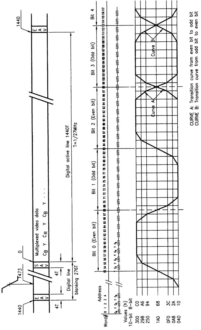
Figure 3.21 D-VITC waveform showing position in line, general form and both 10-bit and 8-bit hex values. Courtesy of SMPTE Journal.
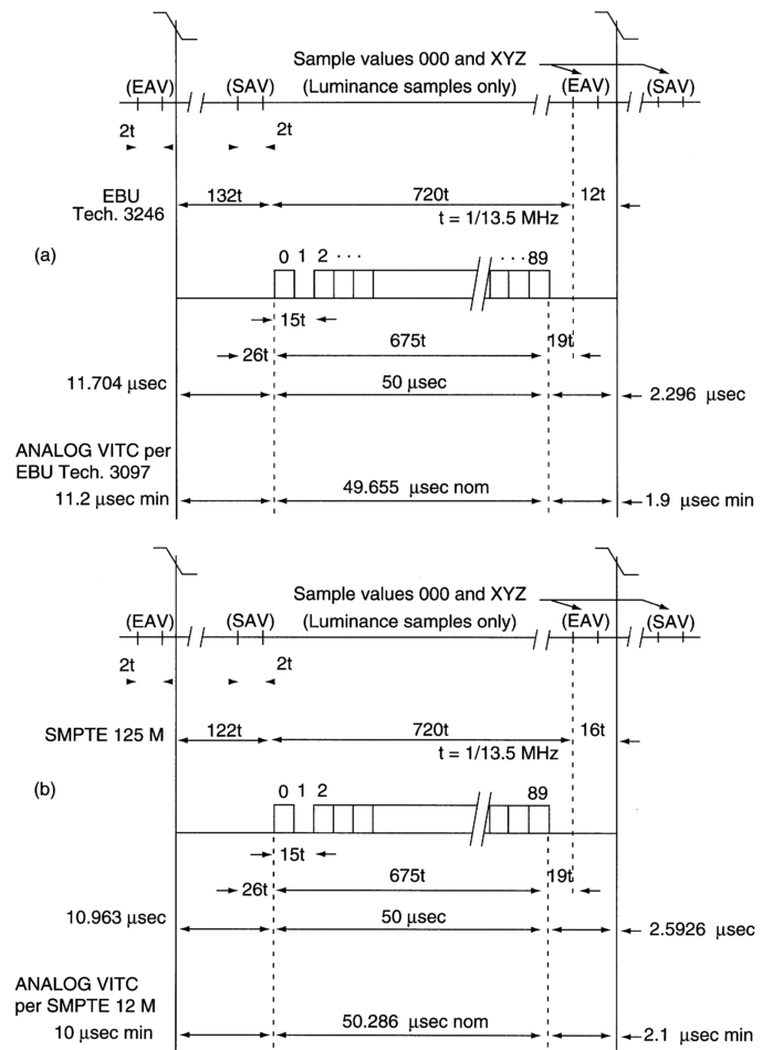
Figure 3.22 Timing relationships between analogue VITC and D-VITC (a) for 625/50 systems and (b) for 525/60 systems. Courtesy of SMPTE Journal.
1125/60 LTC
This is carried as a continuous serial bit stream in 80-bit words, each word having a nominal duration of 33.33 μs (depending on the frame rate), at 1 word per frame. The start of the word (the first transition of bit 0) coincides with the start of Line 1 of each frame, ±1 line. The arrangement of time, binary group and synchronizing data are identical with 525/60 LTC, but there are differences in the assignment of the other bits of the word:
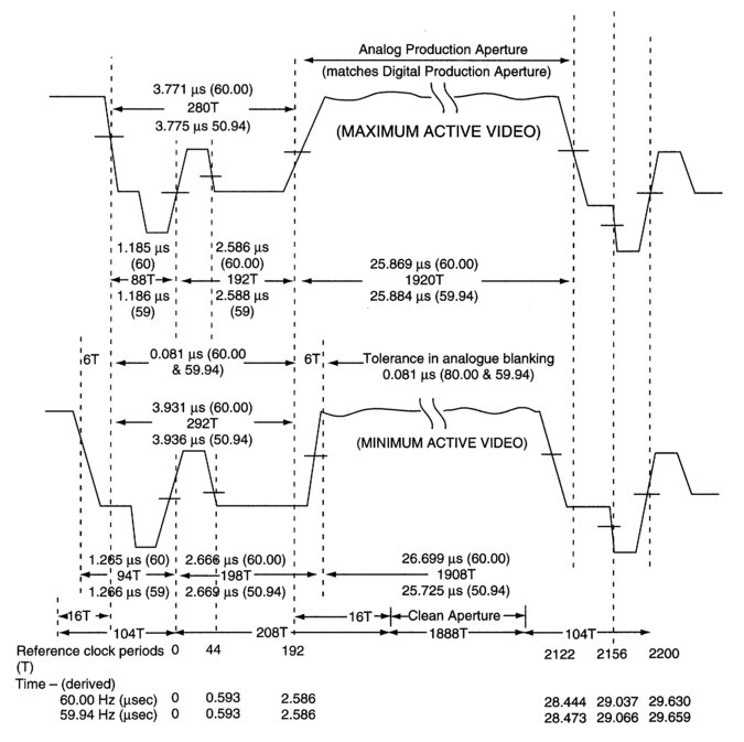
Figure 3.23 Line timing relationships in 1125/60 systems. Courtesy of SMPTE Journal.
- Bits 10 and 11 are unassigned
- Bit 27 remains the bi-phase mark correction bit
- Bit 43 remains as the BGFO flag bit
- Bits 58 and 59 remain as BGF1 and BGF2 respectively.
1125/60 VITC
This is carried as a series of discrete 90-bit words, each word having a nominal duration of 23.18 μs, 1710 reference clock periods (depending on the frame rate). The start of the word is a minimum of 2.7 μs from the start of the line. It ends a minimum of 1.15 μs before the end of the line. The arrangement of time, binary group and synchronizing data are identical
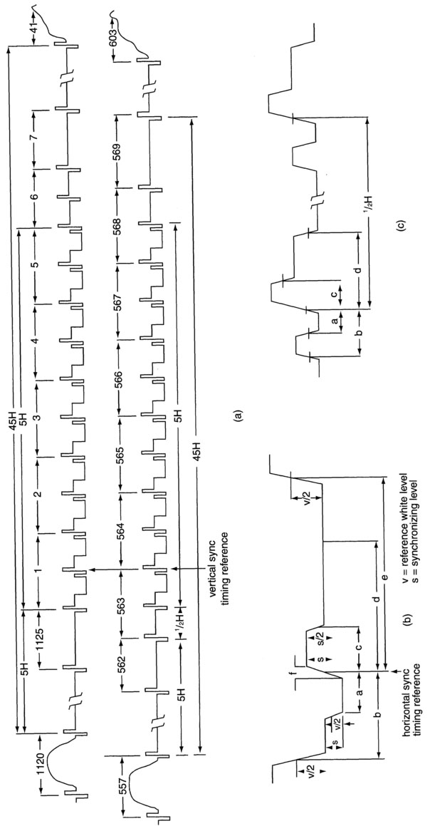
Figure 3.24 1125/60 Field blanking detail (a), Line blanking detail (b) and Field sync pulse detail (c). Courtesy of SMPTE Journal.
with 525/60 VITC, but there are differences in the assignment of the other bits of the word:
- Bit 14 is the drop frame flag bit
- Bit 15 is unassigned
- Bit 35 remains the field marker bit ('0' representing colour fields 1, 3, 5
- and 7; '1' representing colour fields, 2, 4, 6 and 8)
- Bit 55 remains as the BGF0 flag bit
- Bits 74 and 75 remain the BGF1 and BGF2 flag bit respectively.
1125/60 VITC can be placed on any line between 7 (569) and 40 (602) inclusive and can be inserted on multiple lines as long as time address, drop frame and colour frame data are identical. Rise and fall times of the pulse edges are 100 ns ± 25 ns. Logical '0' is represented by a voltage level of between 0-25 mV, logical '1' is represented by a voltage level of 500-600 mV. Amplitude distortions such as over/under shoot or droop must be limited to a maximum of 5% of the peak to peak amplitude of the signal.
24 frame film timecode
Time address, binary group and synchronizing bits are arranged in the same order as 525/60 LTC.
- Bits 10 and 11 are unassigned
- Bit 27 remains the Bi-phase mark correction bit
- Bits 43, 58 and 59 remain BGF0, BGF1 and BGF2 flag bits respectively.
Timecode in ancillary data
SMPTE Standard 259M provides for the transmission of 10-bit, 4:2:2 component and 4fsc composite digital signals over a serial digital interface by way of 75 Θ coaxial cable. Whatever the format of the video information to be transmitted (525/60 or 625/50, component or composite), there are a number of bits in each horizontal sync period not being used to carry video information (Figure 3.25). Some bits are used to carry timing and synchronization information, others to identify the video line number, yet others to carry pan/scan and video indexing data. However, there is provision for packets of ancillary data to be carried in these periods. The data so carried have the name horizontal ancillary data, or HANC for short. HANC may carry AES/EBU audio, audio control data or timecode. Although ancillary data generally can be organized into either 8-bit or 10-bit words, when used for timecode 10-bit words are mandatory.
There are two types of ancillary data packets, Type 1 and Type 2. Timecode is carried in a Type 2 packet. The individual packets are concatenated to form a data block. Figure 3.26 illustrates the format of the data blocks for component video (composite video HANCs have just one ancillary data flag word). The ancillary data flag marks the beginning of the data packet, the data ID identifies the data as being of Type 1 or Type 2, the data block number (Type 1 only) distinguishes successive ancillary data with the same data ID and the data count defines the quantity of data words (up to 255) in the block. In a Type 2 packet the data block number is replaced by a secondary data ID which indicates whether the timecode being carried is derived from LTC or from VITC.
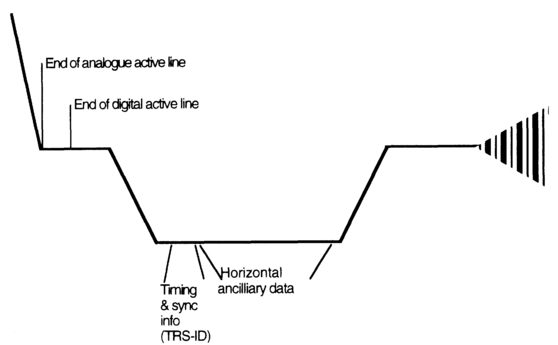
Figure 3.25 The horizontal interval specified in SMPTE 259M showing timing reference points and ancillary data space.

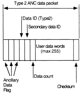
Figure 3.26 Type 1 and Type 2 ancillary data packets showing the data flags, IDs and data words.
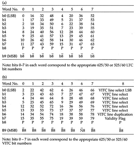
The structure of the ancillary data is illustrated in Figure 3.27. For the transmission of timecode, the Data ID (DID) is set to &164, the SDID, as mentioned earlier, indicates the timecode derivation. It is set to &64 for LTC and to &7F for VITC. One ancillary data block per frame represents LTC, one ancillary data block per field represents VITC. The data count word is set to 8 for LTC and to 9 for VITC. The mapping of the LTC & VITC bits onto the HANC package is illustrated in Table 3.1, where the bit numbers within each map correspond to the bit position in the appropriate timecode word. Bit 9 in all words is the inverse of bit 8.
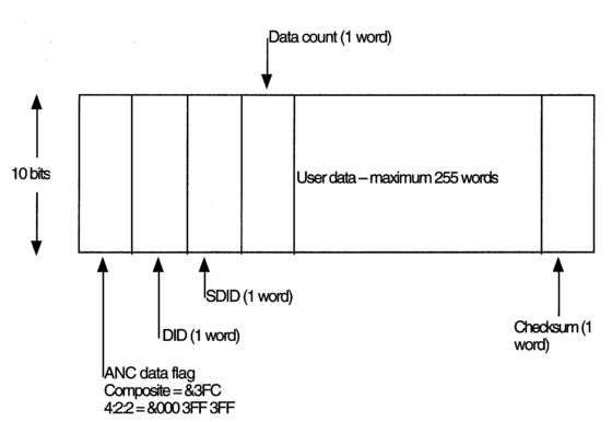
Figure 3.27 A HANC data block showing the component/composite data flag details.
the VITC line allocation is determined by bits 0 to 5 in word 8. Table 3.2 illustrates the detail. Bit 6 in word 8 of the the VITC map, when set to logical '1' indicates that the VITC signal shall be inserted into the selected line number when the video is converted back to analogue and also be repeated two lines later. The Validity Flag, when set to logical '1' indicates a reading error of either the sync bits or the CRCC. The LTC and VITC data words are transmitted within lines 6-22 for 625/50 systems, and within lines 10-20 for 525/60 systems.
Timing and synchronization within MPEG-2 transport streams
MPEG-2 overview
MPEG-2 is fast becoming the de facto standard for the transmission of video and audio over high-speed serial digital links. An in-depth look at the details are out of place in this book and the reader is referred to the Bibliography for published material on this subject. However, a brief overview is included to aid an understanding of how time data are included in this system.
MPEG-2 compresses both video and audio before transmission. Audio is compressed in such a way that its 'continuous' nature is preserved. Video, however, is compressed by identifying common elements within a sequence of frames or pictures, sending these elements relatively infrequently and extracting the identified differences to be sent more frequently. Differences are identified not just by looking backwards to pictures already sent but by looking forward to pictures yet to come. As a consequence, a stream of individual pictures is not sent in its original frame order, but rather has the individual frames uniquely identified and sent in an order that enables a high degree of efficiency in compressing the data.
Table 3.1 HANC data blocks showing the mapping of timecode bits into words within the block for (a) longitudinal timecode and (b) vertical interval timecode. The VITC version carries information concerning the VITC line selection. Both versions carry parity bits for each column (bits 8) and the inverse of bits 8.
Taking as an example the sequence of pictures in Figure 3.28, there are identical picture elements in all three pictures. However, one picture, the I-picture (#1), requires no information from the other pictures in the sequence, and, on the contrary, can supply information to the others. This
Table 3.2 Bits 0-5 within word 8 of the data block determine which video line/s within each field shall carry VITC, and whether VITC is to be repeated on a second line within each field.
| VITC line select | ||||
| b0-b5 | 625/50 | 525/60 | ||
| Field 1 | Field 2 | Field 1 | Field 2 | |
| 0 | Line 10 | 273 | Line 6 | 319 |
| 1 | 11 | 274 | 7 | 320 |
| 2 | 12 | 275 | 8 | 321 |
| 3 | 13 | 276 | 9 | 322 |
| 4 | 14 | 277 | 10 | 323 |
| 5 | 15 | 278 | 11 | 324 |
| 6 | 16 | 279 | 12 | 325 |
| 7 | 17 | 280 | 13 | 326 |
| 8 | 18 | 281 | 14 | 327 |
| 9 | 19 | 282 | 15 | 328 |
| 10 | 20 | 283 | 16 | 329 |
| 11 | 21 | 284 | 17 | 330 |
| 12 | 22 | 285 | 18 | 331 |
| 13 | 23 | 286 | 19 | 332 |
| 14 | 24 | 20 | 333 | |
| 15 | 25 | 21 | 334 | |
| 16 | 26 | 22 | 335 | |
picture will be sent first. The last picture in the sequence, the P-picture (#3), can make use of picture elements it has in common with the I-picture, and it has elements that can be used to help build up the second picture in the original sequence, the B-picture. To fulfil both functions it will have to be sent after picture #1 but before picture #2. The middle picture in the original sequence, the B-picture (#2), requires elements from both pictures 1 and 3 so it will have to be sent last. In order for the pictures to be reassembled in the correct order after decoding, each must be timestamped. Furthermore, as each stream of pictures is likely to be time-division multiplexed with other data streams, there is a need to identify each data stream uniquely in order to demux them at the receiving end. The sequence of pictures headed by an I-picture and followed by B and/or P pictures is called a Group Of Pictures or GOP
For transmission, GOPs are assembled into a packetized elementary stream (PES), then reformatted and multiplexed into a transport stream (TS) as Figure 3.29 illustrates. The TS employs fixed length packets of 188 bytes each, and may carry data from a variety of sources. In order for the forward predicted pictures (P-pictures) and bidirectionally predicted pictures (B-pictures) to be reassembled by the decoder, timing information is provided at three different levels; compression, packetization and transport stream formation. Timestamps — programme clock references or PCRs — are periodically added to the transport stream packets to provide synchronization. The system specification requires the PCRs to arrive at the receiver at least ten times per second, with some applications
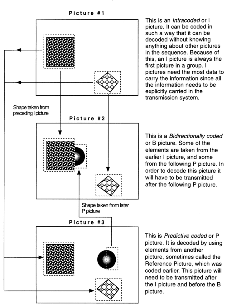
Figure 3.28 MPEG-2 video compression extracts common information from a Group Of Pictures in such a way that it need not be repeated within the sequence.
specifying a frequency of 25 or 30 times per second to correspond with video frame rates.
Compression timing
The most basic timing information is the temporal reference which is added to the data during the compression of each GOP and identifies each picture within the group starting with the I-picture and incrementing up. Figure 3.30 illustrates. There are eight frame rates specified in MPEG-2 and all are locked to a 27 MHz reference clock system, often referred to as the 'clock on the wall'. Since 27 MHz relates to the video scanning rate, video is usually the source for the clock. If the GOPs are coming from a camcorder, its clock will be the reference. If an elementary stream of data is being carried, with no packetization, this will be the sole timing reference for the receiver. Figure 3.31 illustrates an elementary data stream compressed from CCIR 601 digital video.
Packetized data timing
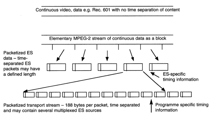
Figure 3.29 A continuous sequence of Groups Of Pictures is arranged firstly into packets, each with its own timing and other essential decoding information, and which may be of either fixed or variable length, then into a data stream of fixed sized packets which may be multiplexed with other streams for transmission. Each packet carries an identifier.
Before data is multiplexed into a TS it must first be assembled into (generally) fixed length packets. These require identifying data in the form of headers containing timing information relating to that elementary stream, such as presentation time stamps (PTS) and decode time stamps (DTS), which are used by the receiving decoder to reassemble the packets into GOPs. These timestamps have a required minimum frequency of occurrence: PTS must be transmitted at least every 700 ms, DTS is optional. The PES packages are not continuous, or even contiguous, blocks of data and may be separated in time. Figure 3.32 illustrates the packetization of the elementary stream into data which might be time separated.
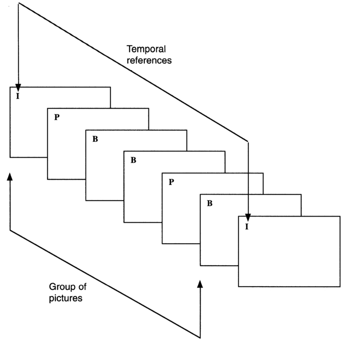
Figure 3.30 A Group Of Pictures starts with an Intracoded (I) picture that can be decoded without information about other pictures in the group. This I picture data will also carry a time reference.
Transport stream timing
Transport streams are subdivisions of PES packages which contain additional header information and, as stated earlier, are exactly 188 bytes long with an additional minimum 4-byte header. The data carried by the transport stream may come from a variety of sources — time division multiplexed, so the headers have to enable the demuxing of the data. Each transport stream package header carries a packet identification (PID), used to reconstruct the various elementary data streams, and the programme clock reference (PCR), used to synchronize the 27 MHz clocks in the encoder and decoder. Figure 3.33 illustrates the formation of the TS from the PES.
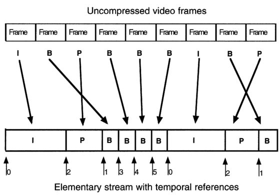
Figure 3.31 After compression the variable length I, B and P picture packets are assembled into a stream. Each packet has an identifier to permit reassembly into the correct sequence.
PCRs are placed in the transport stream headers at least once every 100 ms, with some systems specifying a higher frequency of occurrence such as 25 or 30 times per second for specific video applications, though at the time of writing there are no standards relating to this higher rate use. As the PCR runs on a 27 MHz reference it increments every 37 ns so a 42-bit counter is required to cover a 24-hour period.
The PCR is carried in the TS package headers in two parts, representing counters running at 90 kHz and 27 MHz. As soon as the 27 MHz counter reaches 300 it resets to zero and the 90 kHz counter increments up by one. A 33-bit 'base' specifies the cycles of the 90 kHz clock, with a 9-bit 'extension' specifying cycles of the 27 MHz reference. The 33-bit base accommodates a maximum value of more than 24 hours. The PCR value is calculated as:
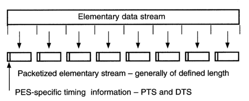
Figure 3.32 The variable length packets of the elementary data stream are organized into fixed length packets which may be continuous or time separated.
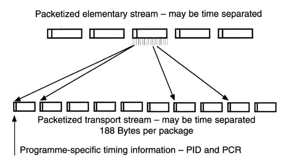
Figure 3.33 The fixed-length packets of the elementary data stream are organized into transport stream packets of 188 bytes/package. These carry programme stream identifiers and may be time-division multiplexed with other transport streams.
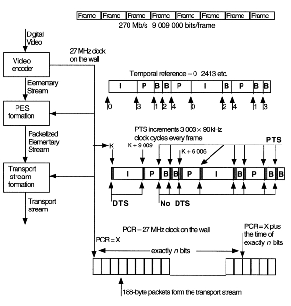
Figure 3.34 The 27 MHz clock on the wall is carried as a temporal reference in both elementary and programme transport streams. It will be used after decoding to reassemble the pictures back into their correct sequence. It may also be used as a synchronizing signal in post production.
PCR (seconds) = [Base/(90 x 103)] + [Extension/(27 x 106)].
The exact clock on the wall time is inserted as the PCR at the head of the transport stream, subsequent PCRs will be exactly the time required for the number of bits that occur between insertions. Figure 3.34 illustrates the relationship between the clock on the wall and the GOPs, PES and TS timestamps.
Reference clock synchronization
MPEG-2 assumes that the transit time between transmitter and receiver is constant for each transport stream package so a software-controlled phase-locked-loop oscillator (PLL) can be used to recreate the PCR in the decoder. When the PCR is first received, or the timing continuity of the PCR changes, the difference can be used to adjust the receiver's 27 MHz oscillator. The system clock tolerance is required to be better than ±30 ppm or ±810 Hz with a rate of change of less than 0.075 Hz/s. The PCRs are required to have an accuracy of ±500 ns, disregarding any jitter due to network jitter etc. As the PCRs are sent relatively infrequently the PLL low-pass filter will have a very narrow pass-band of about 1 Hz. This will eliminate any jitter above its nominal bandwidth and permit stable video to be obtained. Unfortunately such PLLs have long lock-up times, akin to video genlock systems that generate stable video from every third or fourth vertical interval, so are not very suitable for frequent channel switching or surfing. Figure 3.35 illustrates the encode/decode synchronization process.
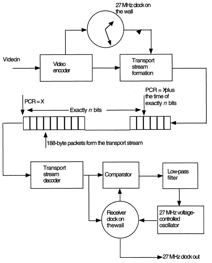
Figure 3.35 The programme clock reference derived from the clock on the wall is carried in every 188-byte package in the transport stream. It is used to synchronize the receiver's clock for decoding.