
Chapter 8
Timecode on location
As this edition went to press, the EBU/SMPTE Task Force for Harmonized Standards for the Exchange of Programme Material as Bitstreams issued its final report. It identified the following requirements regarding timing and synchronization:
- The reference signal for both digital and analogue signals will be analogue colour black. SMPTE RP154 has been enhanced and is being re-issued as a standard. It will include the option of including VITC, and (for 59.94 and 60 Hz related systems) a sequence of ten field identification pulses to assist with the locking of 24Hz related signals and the five-frame sequence implicit in the relationship with 48k ITz.
- Absolute Time Reference for studios should be, where possible, the Global Positioning System (GPS) or equivalent (GLOSNAR), with redundancy receivers. Timecode standard should be the revised SMPTE12M (still under revision at this time).
- For situations where GPS reception is not possible (some locations or moving vehicles) because of poor reception, an alternative time reference will be required.
- For fixed locations GPS should be implemented as the time reference.
Synchronization of video and audio machines
When shooting drama or similar material, sound is often recorded on a separate audio recorder with or without sound back-up on the video recorder. It will help the post-production process if both audio- and videotapes have identical timecodes. It will also help the process if the videotape contains at least a guide audio track. The audio recorder can be fed timecode from the VCR, as this will have the correct colour framing reference.
The audio machine's internal timecode generator must be either slaved to code coming from the VCR, in which case it will need to be set to 'external', or some form of 'momentary jam-sync' must be used. If the audio recorder's timecode generator is to slave-lock to that from the video recorder via a cable, precautions must be taken in the event of a momentary loss of code. Most field audio recorders will have the option of disregarding a few frames containing errors, substituting a regenerated code that will increment up from the last time a valid time address was received. They will revert to the incoming code as long as it becomes valid again within the limits set. If it does not, the timecode generator in the field audio recorder will run independently of any incoming code until reset. If this happens it is important to rejam as soon as possible as the time addresses will gradually drift apart. The audio recorder's timecode generator must not stop generating code at the first non-valid address received. If the camcorder and separate audio recorder need total independence of movement a radio link can be employed. In this case precautions need to be taken against loss of the radio link. If continuous slave lock is employed, some form of diversity radio link may be used. Such a link employs two aerials spaced apart, feeding the receiver unit, which selects the strongest signal received, usually with some form of indication as to relative signal strengths, and thus minimizes the risk of signal loss as the camera moves. This system is of little use if the audio recorder has to move around as well, and is prodigal of available radio channels. A better solution would be to employ some form of automatic jam-sync. In this mode the timecode generator in the audio recorder will lock to incoming code, when available, free-running to its internal oscillator in the absence of signal. It will automatically revert to incoming code when this becomes valid again. When running code in the 'auto' mode it is important that the sound recordist ensures that the audio recorder's timecode generator is re-jammed to timecode from the VCR at the start of each fresh take. This is not just because the two free-running codes (generated by the video recorder, and by the audio recorder respectively) will have drifted; they are driven by highly accurate and stable oscillators. It is because there is always the possibility that one of the generators may have stopped generating code during power-down mode (for example while changing batteries). There is also the possibility that the video recorder may not send code to its output during the stop mode. In Chapter 5, mention was made of the need to ensure that valid code is being received before jamming to it. There are timecode monitors available to provide readout of incoming code. Their use is recommended if the field audio recorder has no integral timecode display.
Radio links
Since LTC is an audio signal it is possible to employ a radio-microphone link to transmit it from one recorder to another. The level of code coming from a generator is likely to be too high for use in its raw state. It will need reducing in level by some 20-40 dB. Having done this the transmitter can be adjusted in the usual way.
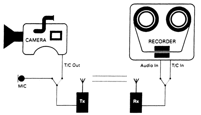
Figure 8.1 Timecode need not occupy a separate radio channel. The link can be switched and the field recorder put in the auto jam mode. Synchronization will be maintained over several minutes.
There is no need for a dedicated timecode radio link. If the sound recorder is equipped with the auto jam-sync facility then a simple switch arrangement at either end of the radio link, coupled with a clear method of operational practice, will permit the link to be switched between audio and timecode (Figure 8.1). In essence, send code over the link prior to the take, and use this code to jam the audio recorder's timecode generator to it. Confirm the audio generator has jammed, then switch the link back at each end to audio and confirm audio is being received. Recording of the take may now proceed. It is probably sensible not to put the audio recorder into record mode until the radio link has been switched to send audio, in order to avoid the post-production personnel receiving an unwanted burst of timecode at the start of each take! A dual-channel radio link can be used to send both timecode and guide audio from the audio recorder to the camcorder, but to avoid interference the two channels used should be spaced apart in frequency by 10% of the lower of the two carrier frequencies (i.e., if the lower frequency is X, the higher frequency should be at least X = 10%). The timecode will not be colour-framed, but could be placed in the user bits of the video timecode, or recorded on a spare audio track.
Portable links capable of transmitting video information are also available. With one of these units taped to the camera, and a receiver at the audio recorder, a locking source is available for the audio timecode generator, though precautions should be taken in the event of loss of signal. More importantly, timecode can be 'burned in' to the video for display on a small monitor. This can be most helpful for the PA, who is not usually in a position to read code from the camera, for logging purposes. Figure 8.2 illustrates one possible arrangement, using a small inserter. The operator contemplating the use of such a link should check its legality in the country concerned.
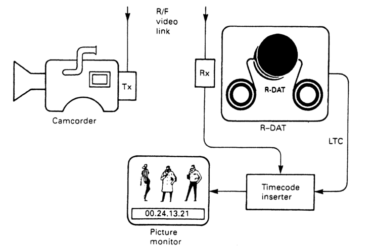
Figure 8.2 A suitable radio link can provide a video feed for a timecode inserter. This burnt-in code can be displayed on a small picture monitor.
Logging for non-linear editing
Perhaps the one drawback to non-linear editing is the time taken to digitize the material shot, and, of course, the finite amount of memory available to hold that material. Both these drawbacks can be minimized if a pre-selection is made of material to be digitized. This in itself can be time consuming, but the process can be speeded up considerably if material shot is accurately logged at the time of recording, not only with start and end timecodes but also such details as scene and take numbers, shot description, person/s shot, lighting/weather conditions, sound track/s and production comments (e.g. N/G, Use this! etc.). Devices are available, and they are hand-held, which permit such details to be preprogrammed in. They will automatically log start and end timecodes, via a radio link from the camcorder or film camera, together with relevant shot detail. They permit the sorting and editing of logged material, and can produce either an EDL or Logging Database for export to either a linear or non-linear editor. These devices will run on either Macintosh or PC and will produce EDLs or Logging Databases for all commonly encountered linear and non-linear editors. They usually have the sync options of record-run, free-run or jam-sync and have clocks stable enough to remain in sync for several tens of minutes in the event of the radio link failing. Figure 8.3 illustrates one such device, which the author has used to great effect while shooting on location for later non-linear editing. As with any radio link the operator is advised to ensure that the frequency used complies with the regulations in the area of use.
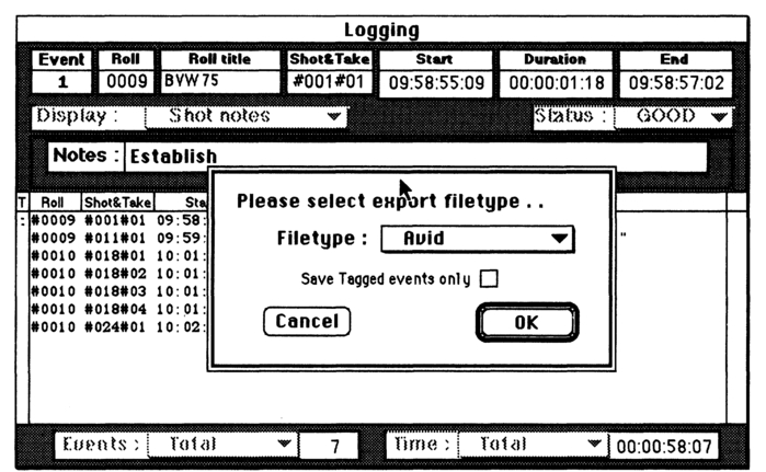
Figure 8.3 An automatic logging device which runs off a radio link from camcorder or film camera. Used in conjunction with a computer it can produce on-shoot timecode logs and Logging Databases for export to non-linear editors. Courtesy of Electronic Visuals Ltd.
Running unlocked with film
At one time, running a field audio recorder and a film camera unlocked was anathema. However, the advent of film cameras with crystal-controlled transports, loaded with DataKode® film stock, and fitted with in-camera timecode generators (see Chapter 5), made it possible to run both camera and audio recorder unlocked. With KeyKoded® film stock there should be no need for a clapperboard, as the offset between the codes on audio tape and film (or the subsequent video off-line copy of the film) can be calculated by a microcomputer on transfer. Indeed, one manufacturer makes a point of needing no clapperboard with their system. However, the use of a clapperboard will ensure synchronization should the technology fail.
Running unlocked with video
Although video and analogue audio can run unlocked as long as the timecode generators are accurate and stable, this mode of working should be treated with care if using a field R-DAT recorder. The sampling clock on R-DAT will need to have a known relationship with video syncs if relative slippage is to be avoided in post-production. Over short periods the clocks in both professional camera and R-DAT will probably be accurate enough to permit unlocked recording as long as the R-DAT's timecode generator is re-jammed at regular intervals. However, some domestic and semi-professional R-DAT machines do not have clocks stable enough to allow this. In any event, long continuous takes should be undertaken only with R-DAT locked to the camera's video reference.
There can also be problems when video camcorders are stopped between shooting sequences. If the camcorder is left in its Standby mode after shooting a sequence the tape will remain in contact with the head drum, and be backwound a few frames. When the VCR button is pressed, control track and timecode should pick up from where they left off, ensuring continuity of colour framing and maintaining synchronization. On a poorly maintained machine this may not happen, and if the tape is unlaced from the head drum then colour framing may not be continuous across the join between tapes, resulting in loss of synchronization.
The playback shoot
There is an increasing requirement for shooting pictures to a pre-recorded sound track (e.g. for a pop video). The pictures will then be post-produced. In this event it will be necessary to provide the following facilities:
- Audio replay machine to run at exactly the same speed as the video recorder
- Timecode on the video recorder that is colour-framed
- Some method of identifying synchronization between pictures and sound in the absence of a clapper slate, or if there is no slating signal recorded on tape
There are a number of ways of achieving the above with varying degrees of complexity, depending on equipment available. These are described below.
Self-resolving of timecode
Some audio field recorders can run locked to their internal timecode generators, rather than running at a nominal speed dependent on the degree of slippage in the friction drive system (Figure 8.4). The tape to be replayed must first have been striped with timecode when being copied from the final mixed audio master, and it would be helpful if a 'click track' is put at the head to aid the performers in vision. If the guide audio can be recorded onto an audio track of the video recorder it will aid synchronization during post-production.
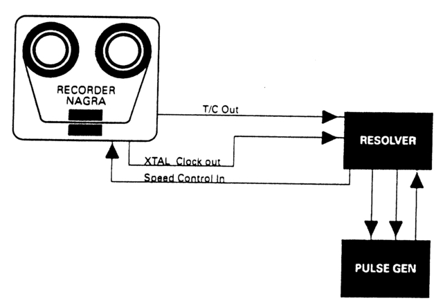
Figure 8.4 For short vision recording runs a Nagra can be made to self-resolve. It uses pre-recorded timecode as a control track, comparing this with its internal clock to control tape speed.
Resolving to video
Although more complex to achieve than self-resolving, resolving to an external video source is much more elegant. This involves comparing the off-tape audio timecode with that being generated by the video recorder (Figure 8.5). The replay speed is now under the control of the timecode from the video recorder. Guide audio can be recorded on one track of the videotape, and timecode from the audio recorder onto the other. The recorded videotape will now have both sets of code available, that generated by the video recorder or camcorder will be colour-framed. The other, recorded from the audio field recorder will correspond to the code laid on the audio master tape. From these two codes the offset can be easily calculated for post-production purposes.
The use of R-DAT for field recording
One of the many advantages digital recorders have over analogue is that synchronization and timing are made much easier as digital data can be stored and clocked out precisely to order under the control of an extremely accurate clock. If the R-DAT machine is capable of being synchronized to an external source of composite video, it will run at exactly the same rate as the camera. If it will accept timecode from the video recorder (earlier R-DAT field recorders will not do this), the code striped onto the audio tape and that striped onto the video tape will be identical (Figure 8.6a). It will, of course, record its own internallygenerated timecode, so it will be necessary to put a clapper or some other slating signal at the head of both video and audio recordings at the start of each tape to ease the process of synching the sound to the pictures in post-production.
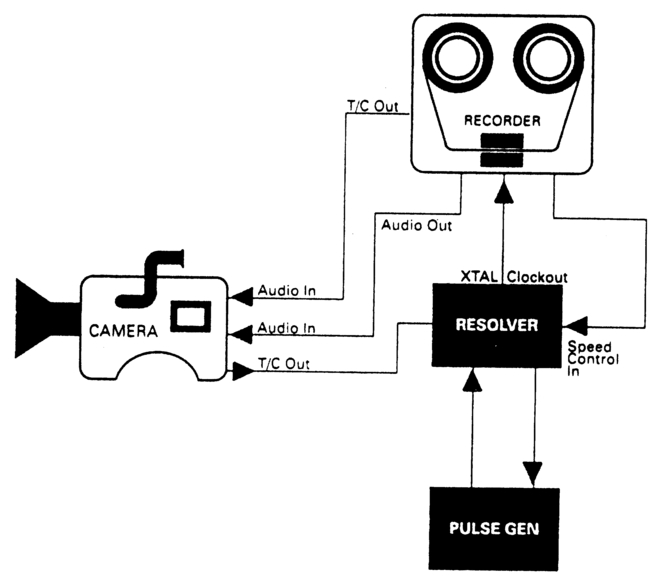
Figure 8.5 A Nagra can resolve to timecode coming from a camcorder. This will lock audio and video firmly together. Guide audio and LTC can be recorded on the audio track of the videotape to act as a guide in post-production.
If an R-DAT recorder has no facility for recording continuous timecode then record, at the head of the take, incoming longitudinal timecode from the video recorder onto an audio channel for a few seconds – 20 seconds is a good duration, since R-DAT machines can take up to 10 seconds to lock up under the control of an edit controller or synchronizer in postproduction (they lock up much faster if fed with an external reference signal) – and then switch the channel back to incoming audio before the actual take. This code can then be used in post-production for calculating the offset between pictures and sound. Figure 8.6b illustrates the procedure. Of course it is important not to stop the R-DAT machine recording between laying down each LTC leader and the take to which it relates. Unlike ordinary analogue machines the same rotating heads, locked to an internal control signal, attend to both record and replay so there is no offset to compensate for when the tape is replayed.
Not all R-DAT field recorders provide indication of the timecode recorded. This is not only a nuisance when it comes to logging the takes, but, perhaps more important, it means that there is no way of checking that a timecode has been received. As the timecode is placed in a subcode within the actual programme sound data stream, the ability to read the timecode either from a play head during recording or by playing back a
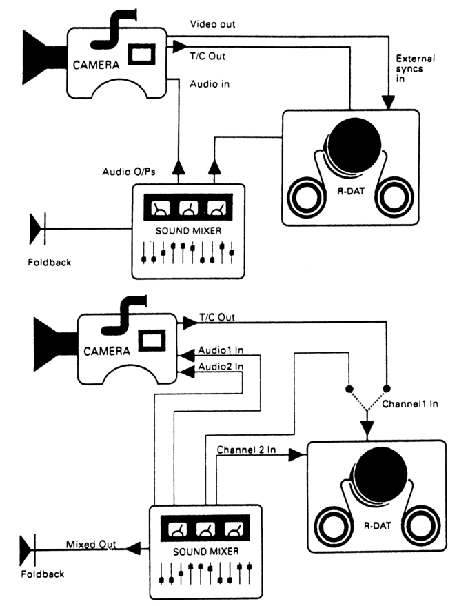
Figure 8.6 (a) When working with R-DAT, timecode can be recorded either on a dedicated track, or a spare digital audio track if working in mono, (b) If working in stereo with older machines without timecode facility, a few seconds of LTC can be recorded at the head of each take on one audio channel, which should then be switched back to audio.
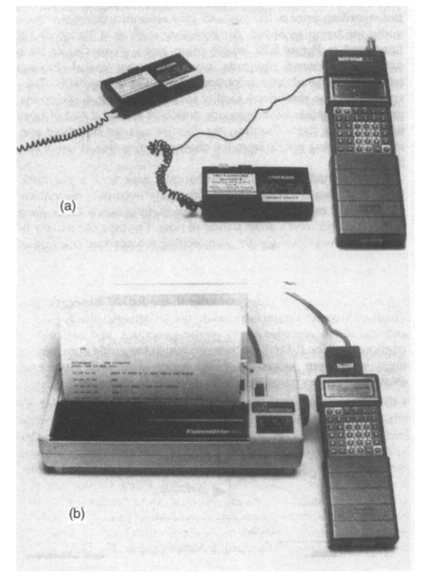
Figure 8.7 (a) A Psion organizer used as a timecode reader. A radio link is optional, (b) Shot lists being typed up at the end of the day from a timecode Organizer. Courtesy of Chris Thorpe Projects.
test recording prior to the take will give assurance that both timecode and audio are being recorded. An accessory such as a Timecode Organizer, illustrated in Figure 8.7a, which plugs into a Psion Organizer to give a display of received timecode, can prove very useful. Incoming code failure is indicated, and an optional radio link is available. This piece of equipment also provides a facility for entering shot descriptions into the organizer, together with timecode details at start and end of takes, and at the end of the day's shooting, the shot listings can be edited and printed out, thus freeing the PA from the chore of typing this all up in the evening (Figure 8.7b).
R-DAT certainly makes the operational aspects of a playback shoot a great deal easier. Locked to its extremely accurate internal clock, and playing back material recorded via an equally accurate clock, there will be negligible drift over a short period of time. The tape can simply be played back, again with perhaps the audio being recorded on one audio channel of the video recorder as a guide for post-production, and the timecode on another channel for the offset. Figure 8.8 illustrates. The same rules apply regarding locking the video recorder to the R-DAT timecode: don't do it. There will be no established relationship between the R-DAT timecode and the video recorder's sync pulse generator, and no colour-framing relationship. The R-DAT machine on which the guide audio was recorded must have been locked to video syncs. This will have ensured an established video frame /timecode address relationship.
Remote timecode generation
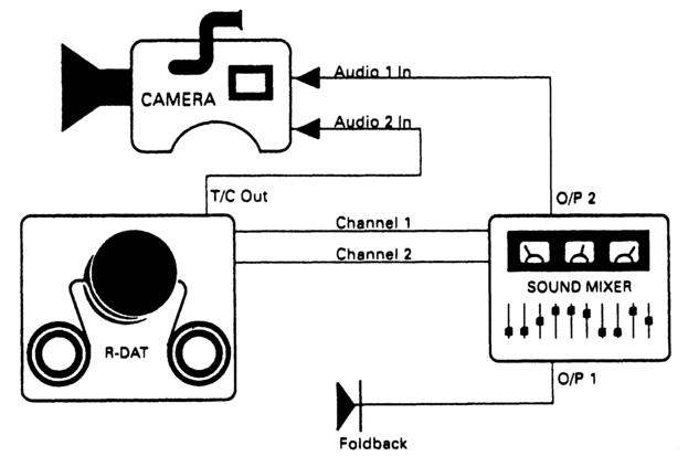
Figure 8.8 An R-DAT machine will be stable enough to run with independent timecode during playback shooting. Guide audio and timecode may be recorded on the audio tracks of the VCR.
If you are using an analogue audio field recorder without an internal timecode generator, then independence from the camera can be achieved if a separate portable timecode generator is used. Its use frees the recordist from both radio links and the need to keep re-jamming to the camera as long as time-of-day code is employed. At the time of writing, portable battery-operated timecode generators have an accuracy of 1 frame per hour, but crystals are coming on the market with a much higher degree of thermal stability, and portable generators with an accuracy of 1 frame in 5 hours can be expected.
Record-run and time-of-day codes
Timecode generators in field recorders allow for two modes of operation. In the record-run mode, when the recorder is put into Pause (not Stop) it will backwind a few frames with the tape loosely laced round the head drum. On pressing Record again, the end section of the timecode and control signals on the backwound tape will be used to regenerate fresh code and control track pulses, which will be laid down seamlessly on tape as soon as the machine goes into 'record'. The contiguous time addresses and the continuous control track will make post-production much easier, as there will be no timecode or control track problems during pre-roll.
Time-of-day code is exactly that. The generator can be set either manually or jam-synched at the start of the day, and within limits the code addresses recorded will represent the passing of time. This means that time addresses across separate takes will not be contiguous, and there may be problems during post-production if insufficient pre-roll time has been left at the start of a take. This form of code can be useful when a number of independent units have to record an event where it is important to have a record of the time of day, to aid continuity. Most field video recorders have the facility to place record-run addresses in the time data bits of the timecode word, and time-of-day addresses in the user bits.
The problem with midnight
At midnight the timecode generator does not blithely carry on through 24h.00m.00s.00f, but instead resets to 00.00.00.00. If a recording is made over this time there could be problems with some edit controllers and synchronizers, which will not recognize the progression through midnight and so may spool the wrong way when searching for a time address. There are three ways of preventing these problems from arising. The recording of a take could be started sufficiently early for it to end well before midnight. Reels and cassettes should be changed before the post-midnight take so that there are no split days on the same tape - either sound or video. Fresh tape(s) could be put into the recorder(s) and production paused until after midnight has passed. Alternatively, if the nature of the events is such that recording over midnight is necessary, as for example it would be when recording New Year celebrations, then the answer is to reset the timecode generator(s) so that they skip past midnight, re-jamming slave generators if necessary: a sensible way might be to advance the 'hours' address to 12 (noon). This will keep the minutes, seconds and frames unaffected for syncing timecode with the actual time of events, which will be a great help during post-production if the events are being shot with multiple independent cameras and recorders.
Cassette changes
It is a good idea to have some indication within the timecode word of the reel number. If time-of-day code is being used this information may be stored in the user bit, and one manufacturer of audio field recorders has provided a facility for easily incrementing the last two digits of the user bits when they are being used in calendar mode. Most people prefer to have the reel number incorporated within the time data, and convention is to put the reel number in the hours digits of the timecode.
If this is done, both video- and audiotapes should be changed together. There will be no danger of the reel number incrementing up accidentally as long as the code is reset to zero and the tape duration is less than 1 hour long. No audiotape recorded on location should ever be split across videocassettes.
Setting the VITC lines
Most field recorders use little thumbwheels to set the two lines on which VITC will be recorded independently of each other. These thumbwheels are often marked with the hexadecimal sequence of symbols 0–F. While there are sixteen symbols in the Hex system, the IEC allows VITC to be placed on any line between 6–22 (319-335) inclusive when used with 625/50 systems, a total of 17 possible lines. It might be supposed that these would permit VITC to be placed either in lines 6–21 to 7–22. This is not the case. Component analogue recorders use line 8 or 10 to record vertical interval sub-carrier: line 7 may be used in PAL systems to carry a pulse identifying the eight-field sequence (it is recorded in field 1); lines 7–15 (320–328) carry field identification signals in SECAM. Most factory settings put VITC in lines 19 and 21. If you are considering altering the VITC lines also bear in mind that 1 in C-format machines have a format dropout that will increase when running at other than standard speed. The tape logs should state which video lines carry VITC, together with any non-standard codes such as a secondary code in the user bits or on an audio track.
Shooting without a slate
It is possible to shoot without the need for a slate if in-camera real-time code is also recorded on the audio tapes by the sound recordist, and the 'ready-to-roll' time (day, hour, minute) is written on the tape box as soon as the tape is loaded onto the recorder. This ready-to-roll information is necessary as the audio recorder timecode may not carry data information, so saving the colourist having to hunt to find the sound reel corresponding to the film negative. If the recorder has no timecode generator, or has one that cannot be jam-synched, a master clock can be used to provide the correct code. If no dedicated timecode track is available, code can be laid down on a spare audio track.
If Aaton code is being used, the later R-DAT recorders will accept the Nagra/ Aaton user-bit organization which carries the date, and modifications are available to allow some R-DAT machines to accept TTL timecode levels, so easing the interface problems with some cameras. Check with your supplier whether or not you have the correct soft- and hardware in the recorder.
Although in-camera codes are quite tolerant of over- or underexposure, do check the settings of the LEDs' intensity – timecodes burned in on a 50 ISO film with the intensity set to 500 ISO could be difficult to read on transfer. A test transfer prior to shooting could save much angst later. If shooting monochrome film, relying purely on real-time code for sound sync on transfer, be aware that most black and white emulsions are relatively insensitive to the red light from the in-camera code generator a 250 ISO monochrome negative stock could have a sensitivity of 80 ISO in the red end of the spectrum – so have a transfer test done before shooting starts. Check also, each time film is to be loaded, that the LEDs generating Aaton code are twinking equally brightly; no particles of dust should cover any of the LEDs. Regularly, say every couple of years, check the stability of the timecode generators. They should have a stability better than 1 part in a million (approx 1 frame in 10 hours). A good check of picture/sound time clock accuracy is to shoot a marble bouncing on a marble or ceramic tiled surface. One last point – a battery which is too low in charge to run the film camera can still keep the real-time clock going for a couple of hours so do not disconnect it until a fresh one is to hand.
The Global Positioning Satellite (GPS) system and timecode
The concept
The concept behind the GPS system is that of using time-of-arrival differences in the signals received from a number of satellites in order to compute position. As long as the exact position of each satellite is known, and each satellite transmits identical time signals simultaneously with every other satellite, then the position of the receiver can easily be calculated. Figures 8.9 to 8.11 illustrate the concept. In Figure 8.9, signals are being received from two satellites. If the distance from one satellite is r, and the distance from the other is r + Δr, then the receiver must be at either of points X. If r is unknown, but Δr is known, then the receiver must lie along the curve Y-Y, as Figure 8.10 shows. Δr is calculated from the time-of-arrival difference between the two transmitted signals. In Figure 8.11, signals are being received from three satellites. The differences in the arrival times of the three time signals, r, Δ1r, Δ2r, enable the receiver's position to be calculated precisely, with no ambiguity. In practice, four satellites are required as the receiver may be either above or below the elevation of one or more of the satellites.
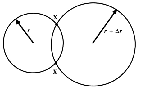
Figure 8.9 If two generators transmit identical time data, and a receiver in an unknown position generates identical time data, the difference in time data (Δr) brough about by the different journey times, on arrival at the receiver will enable its position to be computed, though with a degree of ambiguity.
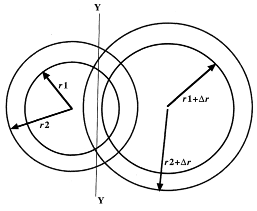
Figure 8.10 If two generators in known positions transmit identical time data but the receiver time is unknown, the difference in time data (Δr) brought about by the different journey times, on arrival at the receiver will enable the receiver's position to be computed as being along a curved line.
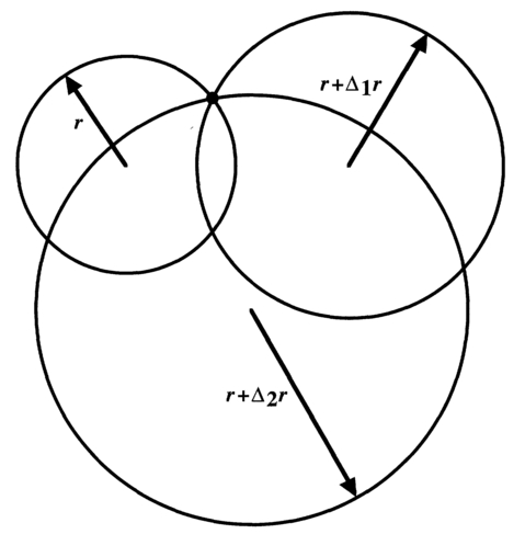
Figure 8.11 If three generators in known positions transmit identical time data but the receiver's time is unknown, the differences in arrival times between their three signals will enable the receiver's position to be computed unambiguously.
Spatial positioning
For GPS to work, the positions of the GPS satellites (SVs or Space Vehicles) must be known. Geostationary satellites cannot be used as the laws of physics determine that for a satellite to be geo-stationary, it must lie on the plane of the earth's equator. The SVs follow a precisely computed orbit, using an Earth Centred Inertial coordinate system. In other words, their positions are known relative to the effective centre of rotation of the earth (or rather, the effective centre of the earth at 12.00 hours UTC on 1 January 2000).
GPS receivers use an Earth-Centred Earth-Fixed (ECEF) coordinate system. In other words, their position is computed in terms of latitude and longitude (and height above/below a computed ellipsoid shape, acknowledging that the earth is an oblate (flattened) spheroid, rather than a sphere).
Signal characteristics
The GPS SVs transmit on two common frequencies: LI = 1575.42 MHz and L2 = 1227.6 MHz. These are 154 times and 120 times the perceived data rate of 10.23 MHz respectively. Interference between satellites is avoided by the use of Pseudo Random Noise (PRN) scrambling of the data, a technique employed in the NICAM stereo sound transmission system, combined with a Binary Phase Shift Keying (BPSK) of the carrier (again, similar to techniques employed in NICAM).
The LI frequency link consists of three components, in phase quadrature with each other. One component, the precision P code, is a ranging code of seven days' length, carrying highly accurate time data. The US military reserve the right to make this code unavailable to the general public by substituting another (Y) code, details of which are not in the public domain. For this reason, this code is often referred to as the P(Y) code. The third component is the C/A (coarse/acquisition) code which allows the P(Y) code to be acquired by the receiver. In addition to the P(Y) and C/A codes, the LI link carries system (NAV) data such as SV ephemerides, system time, SV clock behaviour, status messages and instructions concerning the switching between P(Y) and C/A codes.
The L2 frequency link carries either the P(Y) or the C/A codes, selectable by ground command. It can also carry the P(Y) data without the NAV data.
Time data
GPS disseminates time data as Universal Coordinated Time (UTC), in a form capable of being used for time synchronization throughout the world. UTC is a composite form of time, having data inputs from both atomic clocks and a time scale derived from the rotation of the earth with respect to the sun (UT1).
Atomic clock time, International Atomic Time (TIA), is highly accurate, being derived from atomic standards held in 50 timing laboratories in different countries, and computed by the Bureau International des Poids et Mesures (BIPM) in Paris to give a statistically definitive time. It is sometimes called a 'Paper Time' since it is not kept by a physical clock.
Irregularities in the earth's orbit, variations in the tilt of the equator and polar wobble result in the length of solar days (and hence of hours, minutes and seconds) varying. These are compensated for to give UT1, which defines the actual orientation of the ECEF coordinates with respect to space and celestial bodies. There are also variations in the rotational speed of the earth and, as a consequence, solar time (UT1) is irregular. Since navigation and both civil and military timekeeping depend on having a uniform time scale, these variations are computed out by the International Earth Rotation Service (IERS) to form UTC, which has seconds of equal length to TAI. This does not wholly solve the problem since a TIA day is slightly shorter than a UTC day. The difference is in the order of several milliseconds per day, and can add up to a second or so over a year. The IERS determine when to add or subtract leap seconds so that UTC never differs by more than 0.9 second from TAI. The compensation is carried out either in the last minute of the UTC year or in the last minute of June.
The US Naval Laboratory maintains a set of more than twenty caesium atomic clocks and, using astronomical data, generates its own version of UTC, known as UTC(USNO), which is not allowed to vary by more than 1 ms from UTC. Because UTC is periodically corrected, GPS time differs with respect to it. The NAV data contains information for relating GPS time to UTC.
Applications
With suitable ancillary equipment, video cameras and camcorders can be genlocked to GPS. Timecode generators can jam-sync to GPS. Because of its accuracy and stability, GPS time can be used to 'tune' free-running timecode/sync pulse generators, permitting multi-camera shoots to be undertaken with complete confidence without the need for periodic re-jamming of the timecode generators. The GPS signal cannot normally be received by a receiver sited indoors, though the author has used GPS as a synchronizing source within the Faraday cage of an aeroplane, when shooting onto video. Figure 8.12 illustrates a GPS locked timecode generator. For timecode purposes the GPS receiver must receive GPS signals from a minimum of three SVs. Usually, signals have to be received from four SVs in order to accurately establish the position of the GPS receiver, remembering that a positional error of 1 metre will result in a 3 ns timing error.
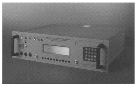
Figure 8.12 A commercially available IEC timecode generator capable of being locked to GPS. Courtesy Radiocode Clocks Ltd.
Terrestrial time and date code sources
The code format and transmission
There are a number of terrestrial standard time data and frequency transmitters around the world, all of which provide highly accurate time data related to UTC. Frequency details and addresses are given in Appendix 9. In the UK, the MSF time and date code is broadcast from Rugby (latitude 52° 22′ N, longitude 1° 11′ W). The estimated radiated power is 27 kW from a substantially omnidirectional antenna, giving effective coverage over the UK and northern and western Europe. It can be satisfactorily received in Iceland, Finland and Gibraltar. Carrier frequency is maintained at 60 kHz to within two parts in 1012.
Simple on/off carrier modulation is used, the timing of the pulse edges being governed by the seconds and minutes of UTC, which is always within 1 second of GMT. Every UTC second is marked by a carrier 'off' preceded by at least 500 ms of carrier 'on'. This second marker is accurate to within 1 ms. The first second of each minute (second 00) nominally contains 500 ms of carrier off, though other data may be transmitted by carrier on/off modulation between 25 ms and 330 ms. Seconds 01 to 59 (exceptionally 58 or 60) always begin with at least 100 ms 'off' and end with at least 700 ms of carrier 'on'. Seconds 01–60 carry information, in signalling bit pairs (A and B), about the current minute, hour, day of week, month and year, and about the difference between TIA and UTC, this difference being called DUT code (DUT1). DUT1 is signalled to the nearest 100ms in the range +800 ms. A positive number means that GMT is at a higher count than UTC. Figure 8.13 illustrates the detail of the time and date code for second 00 and seconds 01–60.
Allocation of signalling bits
Bits 17B–*51B and bits 01A–*16A inclusive are currently set to '0', as are bits *52B and *59B, their future use being reserved. To identify the minute, bits *53A–*58A are all set permanently at '1' and are always preceded by bit *52A at '0' and followed bit *59A at zero. This sequence 01111110 never appears anywhere else in bits A, so it uniquely identifies the following 00 second minute marker. In minutes shortened or lengthened by the addition of a positive or negative leap second, the second numbers identified as *nn are correspondingly increased or decreased by one, shifting the start of the time and date code by one second relative to the start of the minute. When UK civil time is offset from UTC by one hour for British Summer Time, bit *58B is set to '1'. Bit *53B is set to '1' during the 61 minutes immediately preceding the change, the last being minute 59, when bit *58B changes. Table 8.1 gives the details Bits 01B–16B are used to signal the DUT code value. Table 8.2 gives the details
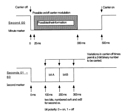
Figure 8.13 The Rugby MSF Terrestrial Time and Data Code Transmission marks the start of each minute epoch by turning the carrier off for 500 ms at the start of second 00 (top). Other data may be carried during the 500 ms Minute Marker. Time data are carried by turning off the carrier for up to 300 ms at the start of each second epoch (bottom). The 'off' duration of the second marker is used to code a 2-bit binary number which when combined with the other 59 (sometimes 58 or 60) bit-pairs enables time and date information to be carried.
Service continuity
The MSF 60 kHz from Rugby is transmitted continuously except for monthly and annual routine maintenance periods. The monthly maintenance period takes place on the first Tuesday of every month from 10.00 UTC to 14.00 UTC (11.00 BST to 15.00 BST). The annual maintenance period takes place over a two-week period in summer. During this time, the MSF signal is absent during the daytime and restored overnight, though the overnight transmission is not guaranteed. The dates for the annual maintenance breaks can be obtained from the National Physical Laboratory Time and Frequency Service (+44 (0) 181 943 6493).
Applications
With suitable ancillary equipment, video cameras and camcorders can be genlocked to the MSF signal. Timecode generators can jam-sync to MSF. Because of its accuracy and stability, MSF time can be used to 'tune' free-running timecode/sync pulse generators, permitting multi-camera shoots to be undertaken with complete confidence without the need for periodic re-jamming of the timecode generators. MSF can normally be received indoors, but can be prone to local interference (in the author's experience,
Table 8.1 Mapping details of the time and date code carried in bits A of the bit pairs in seconds 17–57 (occasionally seconds 16–56 or 18–58).
| Binary Coded Decimal Year (00 - 99) |
| 80 40 20 10 8 4 2 1 |
| *17A *18A *19A *20A *21A *22A *23A *24A |
| BCD Month (01 -12) BCD Day of Month (01-31) Day of Week1† |
| 10 8 4 2 1 20 10 8 4 2 1 4 2 1 |
| *25A *26A *27A *28A *29A *30A *31A *32A *33A *34A *35A *36A *37A *38A |
| †0 = Sunday to 6 = Saturday |
| BCD Hour (00 - 23) BCD Minute (00 - 59) |
| 20 10 8 4 2 1 40 20 10 8 4 2 1 |
| *39A *40A *41A *42A *43A *44A *45A *46A *47A *48A *49A *50A *51A |
| Minute identifier |
| Bit *52A set to '0' |
| Bits *53A, *54A, *55A, *56A, *57A and *58A are set permanently at 'Y |
| Bit *59A set at '0' |
| Sequence 0 1 1 1 1 1 1 0 never appears elsewhere in bits 'A' so the following second 00 minute marker is uniquely identified |
| Parity Bits |
| Bit *54B, taken with bits *17A - *24A inclusive provides an odd number of l's |
| Bit *55B, taken with bits *25A - *35A inclusive provides an odd number of l's |
| Bit *56B, taken with bits *36A - *38A inclusive provides an odd number of l's |
| Bit *57B, taken with bits *39A - *51A inclusive provides an odd number of l's |
fluorescent lights can cause problems), and reception is sometimes poor in steel-framed buildings. Reception is almost certain to be bad if the receiver's antenna is within a Faraday cage (such as is sometimes found as part of the fabric of television and radio studios and control rooms.
Genlocking and jam-syncing
When a number of camcorders are shooting the same event, it will be important for post-production that their timecodes match. Record Run codes cannot be used for the simple reason that the different camcorders
Table 8.2 Mapping details of the DUT code (see text) carried in the B bits of bit pairs 01–16. At the time of writing, bits 01A–16A are set to '0'.
| DUT1 | Positive | DUT1 | Negative |
| 0ms | no bits set to '1' | -0ms | no bits set to '1' |
| +100ms | bit 01B set to '1' | -100ms | bit 09B set to '1' |
| +200ms | bits 01B & 02B set to '1 | -200ms | bits 09B &10B set to '1' |
| +300ms | bits 01B to 03B set to '1' | -300ms | bits 09B to 11B set to '1' |
| +400ms | bits 01B to 04B set to '1' | -100ms | bits 09B to 12B set to '1' |
| +500ms | bits 01B to 05B set to '1' | -500ms | bits 09B to 13B set to '1' |
| +600ms | bits 01B to 06B set to '1' | -600ms | bits 09B to 14B set to '1' |
| +700ms | bits 01B to 07B set to '1' | -700ms | bits 09B to 15B set to '1' |
| +800ms | bits 01B to 08B set to '1' | -800ms | bits 09B to 16B set to '1' |
will be recording over different time epochs, so Free-run code must be used with the option of making the code Time-of-day. If difficulties are to be avoided with the 8-field sequence in 625/50 systems (4-field in 525/60 systems) in any subsequent editing, the timecode should be related to the appropriate field sequence. In order to satisfy these requirements ensure that camcorders are genlocked before jam-syncing. In the author's experience there are two ways of achieving this with simplicity on location.
The least technologically complex, but more fiddly, way is to designate one camcorder as Master. Its timecode generator should be set appropriately to Free-run and Time-of-day (or some other time agreed with the picture editor and/or sound dubbing mixer if possible). Each other camcorder should be brought up to the designated master in turn and firstly genlocked to it by connecting VIDEO OUT on the master camcorder to GENLOCK IN on the slave, then connecting TIMECODE OUT on the master camcorder to TIMECODE IN on the slave, with the slave machine's timecode generator set to FREE RUN. As soon as the timecode on the slave machine has locked to the master (indicated by both machines displaying the same timecode value) the slave machine can be disconnected. Depending on the nature of the material being shot, and on the relative accuracy of the sync pulse generators in the various camcorders, this process may have to be repeated at intervals throughout the shoot as the various SPGs drift apart. Figure 8.14 illustrates the procedure.
An alternative method of jamming camcorders together is to equip each with its own external timecode/video sync generator. These can be individually set by plugging them into a master generator, which itself may be locked to GPS or MSF or similar. More importantly, the accuracy of the individual generators over a period of time can be checked against the master, though typically their drift is less than 1 frame per day. Alternatively a single unit may be jammed to a master generator, then connected to each camcorder in turn, connecting first the video then the timecode, so that each camcorder has been momentarily genlocked then jam-synced. The danger with this method is that you are now reliant on the accuracy of each camcorder's internal SPG which may not have sufficient stability to maintain sync for more than an hour of so. Similar devices can be fitted to field DAT recorders, supplying not just timecode, but a wordclock or video sync feed as well. Figure 8.15 illustrates such devices.
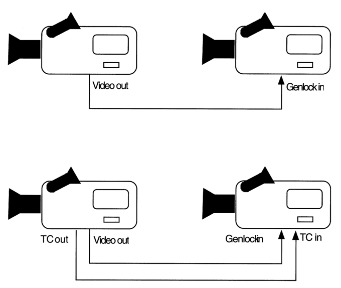
Figure 8.14 Momentarily genlocking and jam-syncing a pair of camcorders. Designate one unit as the Master and set time code running. Feed its video out into the genlock input of the Slave. Keeping the genlock feed in place, connect timecode from Master to Slave and jam the slave's timecode generator to the master.
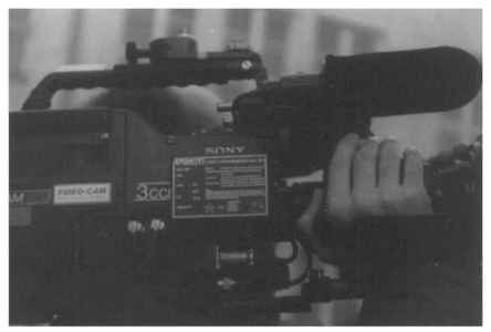
Figure 8.15 A commercially available highly stable timecode and video syncs generator. It can be jammed to a Master and its stability can be checked. Courtesy Ambient Recording GmbH.