Chapter 5
Timecode and film
Introduction
For many years, people working with film have employed a system of film footage numbering, commonly called 'key numbers'. These are printed along the edge of film stock at the time of manufacture as a latent image, becoming human-readable when the film is processed. The purpose of these numbers has been to facilitate the work of the negative cutter, once the film editor has done his or her work (Figure 5.1). In addition to the key number, a 'strip number', having a random relationship to the key number, has also been present to act as a check in the event of duplicated key numbers (always a possibility with a full-length feature film, where hundreds of thousands of feet of film may have been shot). The key number identifies the film type, the printer number (part of the quality control system), the perforation equipment and the footage count. As some scenes may be less than 1 ft long (especially in pop music videos) there may be no key number present in a particular shot. Recent developments in film production have resulted in the marriage of traditional film numbering systems with timecode. This chapter examines the coding systems available, together with the options expected to be developed in the near future.
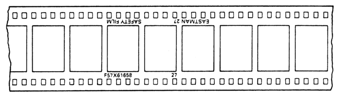
Figure 5.1 The original style key number
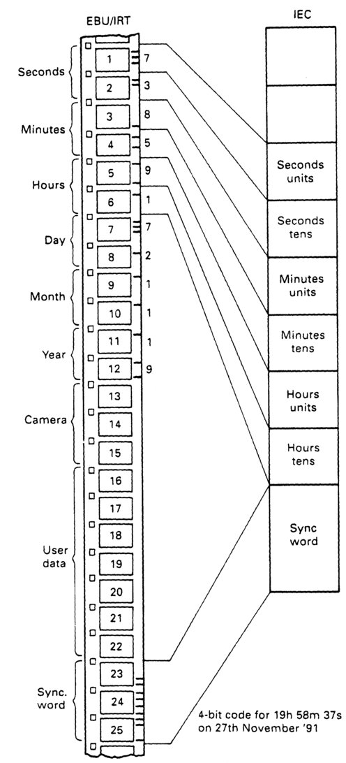
Figure 5.2 16 mm timecode recorded at the time of shooting within the camera as latent images along the opposite edge to the perforations.
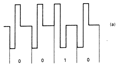
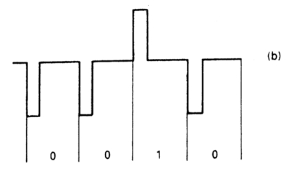
Figure 5.3 16 mm timecode recorded magnetically by either phase shift keying (a) or by a RZ code (b).
EBU/IRT and EBU/TDF timecodes
These codes were developed in the 1970s by the Institut für Rundfunktechnik in Munich, in collaboration with Telediffusion de France. They both carry timecode information as defined in EBU document 3096, and provide time and date of shooting information together with the camera number. The code is recorded either optically or magnetically along the film edge of 16 mm film. Figure 5.2 illustrates the optical form of the code. Each codeword occupies 25 frames, and there are 4 bits of information per frame length, a data rate of 100 bits per second. The code is binary coded decimal. The optical form of the code is straightforward NRZ. The magnetic forms of the code differ slightly between the IRT and TDF versions, with IRT specifying pulse polarity (return to zero) to determine logical Is and 0s, and the TDF version specifying phase shift keying. Figure 5.3 illustrates the differences. The code extends past midnight to 28 hours. This is to avoid the code resettling to 00.00.00.00 at midnight, which might cause problems in post-production.
SMPTE film codes
Timecodes for film are specified in SMPTE Recommended Practice RP 136-1990. There are two versions, B-format and C-format. The arrangement of time and data bits in both formats is that of the IEC 525/60 code covered in Chapter 3. There are differences in the synchronizing bits, as the two versions have different implementations. The C-format code is designed for application when the film is moving continuously both during filming and replaying. The codeword contains 80 bits, and should begin at a point adjacent to the centre of the frame bar (the frame line), though any point between the frame line and the centre line of the frame is acceptable (Figure 5.4). The bit allocation is identical to the 525/60 version of IEC longitudinal timecode. Arriflex have developed an in-camera recording system based on this format. The B-format code is recorded in blocks, each block being complete in itself. It is designed for use with equipment that has intermittent film motion, though it can also be played back in continuous mode. The format is illustrated in Figure 5.5. There are 112 bits to the complete word:
Bits 0-7 and 104-111
These are timing bits. They are alternate logical 1s and 0s. Bits 0–7 start 0,1; bits 104–112 start 1,0.
Bits 8-23 and 88-103
These are synchronizing words. They are identical, and have the same form as the LTC synchronizing word discussed in Chapter 3.
Bits 24-87 have the same allocations as bits 0-63 of the 525/60 version of IEC longitudinal timecode.
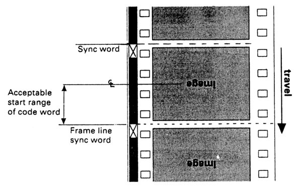
Figure 5.4 SMPTE C-format film timecode.
The gaps between the blocks are a minimum of 10% of the frame length (a frame length being the distance between two successive frame lines). To reduce the d.c. content of the code, the inter-block gaps should be filled with alternate Os and 1s. The lateral positioning of code on the film will depend on the particular format being used, and is laid down in various SMPTE Recommended Practices. The bit allocation between two formats is compared in Figure 5.6.
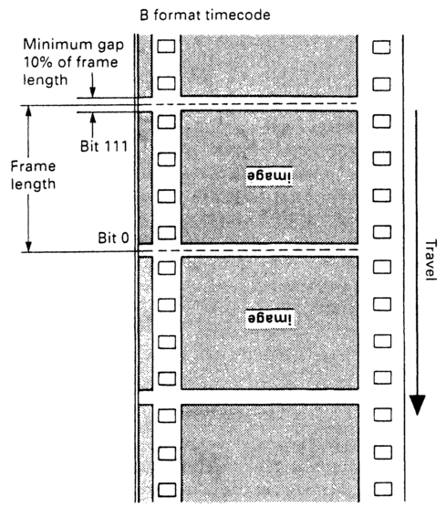
Figure 5.5 SMPTE B-format film timecode.
Both B- and C-format versions of the code employ biphase mark coding. They can each be recorded on film optically or magnetically. On final (release) prints, the timecode at the start of the picture is 0lh 00m 00s 00f. All frames prior to the start of the picture are coded 0lh 00m 00s 00f. On films with more than one reel the picture start is indicated by 01h 00m 00s 00f, with all preceding frames being similarly coded. Successive reels are numbered similarly, with the hour increasing by 1 for each successive reel.
Arriflex 16 mm cameras always use the C-format code. It is recorded in the magazine where the film movement is continuous. Arriflex 35 mm cameras use both 'in gate' and 'in magazine' methods, depending on the model.
Film binary groups data
At the time of writing the use of the binary groups is specified in SMPTE Recommended Practice 135-1990. This provides for information concerning the shoot to be placed in the user bits. The decision as to whether to provide/use this data is left to the discretion of the equipment manufacturer/user. The binary group flag bits indicate the use of the binary groups for carrying this data, which contains the date of the shoot together with camera, roll/tape, scene, take and production numbers, and details of the shot material (daylight/ tungsten, day/ night, sync/non-sync etc.). Details of the code are given in Appendix 4. There is now an SMPTE standard 262m) for the 1.1 setting of the flag bits to indicate the use of the binary groups for additional data. Multiple timecodes, production data, titles, transmission and remote control data are all possibilities. Appendices 4 and 5 give an outline.
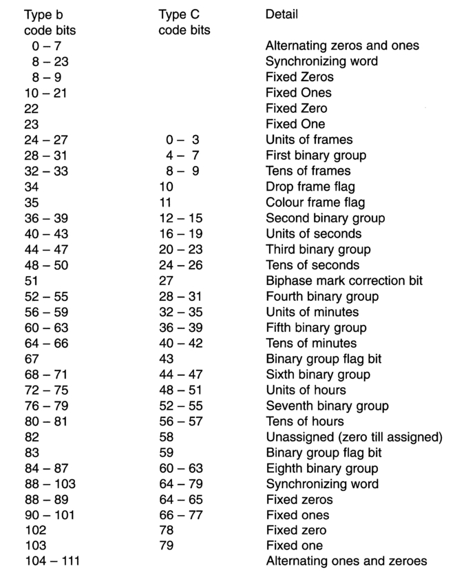
Figure 5.6 SMPTE code format bit allocations compared.
Datakode®
In the early 1980s, the Eastman Kodak Company developed a method of coating film stock with low-density gamma ferric oxide, approximately 0.005 mm thick. The film base was coated on the non-emulsion side. Time data could be recorded onto this coating magnetically, and later replayed either during film to videotape transfer or for viewing. Called DataKode®, this was not intended for release prints. The coating reduced the transmittance of the film stock slightly as additional dyes were required to keep the density neutral. This was of no consequence when shooting as the coating was on the film base; nor was it expected to cause any problems either to the printers or in the review rooms. However, as with all magnetic record/replay systems, contact between record/play head and magnetic surface is necessary to maintain consistent playback quality (freedom from dropout, resolution). The risk of scratches arising from this contact precluded the use of the picture area for this code, so although the coating covered the entire film surface only a narrow strip along the edge of the film stock could be utilized. There were further problems associated with the installation of record and confidence heads in camera instant-change magazines and the risk of mixing different types of film stock, so in the end the system was not adopted for 16 mm use.
Eventually the Datakode was abandoned altogether, and a machine-readable barcode system was developed, called KeyKode®. Details of KeyKode are given later in this chapter.
Aaton and Arriflex timecode systems
Two companies, Aaton des Autres and the Arriflex Corporation, have developed in-camera timecode recording systems. Aaton have taken the route of encoding the time data in the form of matrices of 91 dots (13 columns of 7 lines) per frame, with specific sequences of timecoded frames alternating with additional information concerning the shoot. Their approach has been to develop a dedicated range of equipment to perform such tasks as setting the timecode and user bits, and creating databases for use in film/video transfer and subsequent post-production. The Arriflex approach has been to record time data in standard SMPTE RP136-1990 formats (both B- and C-formats are supported) though at the time of writing the SMPTE RP 135-1990 user bit options for the carrying of additional data are not implemented.
AatonCode
Of the 91 dots in the 7 x 13 matrix, 64 carry time and user bit information as standard SMPTE/EBU code; a further 27 bits carry control and synchronization information. The blocks are recorded two frames down from the gate, the offset being compensated for at the time of recording. The matrix is exposed onto film by a row of seven red LEDS. When code is running, these can be seen twinkling in the camera before the magazine is loaded, though this should not be taken as a confidence check as LEDs have been known to 'stick' on or off due to failure in the drive electronics. In the 35 mm film format these blocks are recorded on the outside of the outside of the sprocket holes on the opposite side of film to KeyKode®. In the 16 mm film format the code is recorded between the sprocket holes, on the same side as KeyKode®, which is recorded outside the sprocket holes. With the Super-16 format the code is also recorded between the sprocket holes, and although there was some overlap between the AatonCode and KeyKode® (the human-readable characters within KeyKode® are larger than the machine-readable barcode), and also between AatonCode and traditional edge numbers, different emulsion dye colours are exposed so that each can be easily read.
The 64-bit 'core' of the Aaton code block is in accordance with SMPTE RP 135-1990, which means that the user bits can contain date, scene, take, roll, production and equipment identification codes. The 35 mm form of the code also incorporates a zero frame indicator.
In the 35 mm form of the code, human-readable data are contained in a sequence 'paged' over a number of frames, with each sequence containing one or two numbers or letters in the following sequence:
| R | XX | XX | Roll number |
| TK | XX | XX | Take number |
| SC | XX | XX | Scene number |
| E | XX | XX | Camera number (may be designated CM) |
| P | XX | XX | Production number |
| YY | MM | DD | Date |
| HH | MM | SS | Time |
| s | Zero frame indicator |
In the 16 mm form of the code 6 frames in 24 provide the following human-readable information:
| Time | :HH | :MM | :SS | every second |
| Date | :YY | :MM | :DD | every three seconds |
| Equipment ID | :EQ | :XX | :XX | every three seconds |
| Production ID | :PR | :XX | :XX | every three seconds |
Examples of the AatonCode are illustrated in Figure 5.7.
Arriflex Code
In the Arriflex Film Identification and Sync System (FIS), timecode is recorded as a series of stripes along the film, between the picture frames and the sprocket holes, on the same side as KeyKode®. Film exposure is from a single LED, either in the gate or within the magazine. If the LED is in the gate, and B-format code is being recorded, a microprocessor within
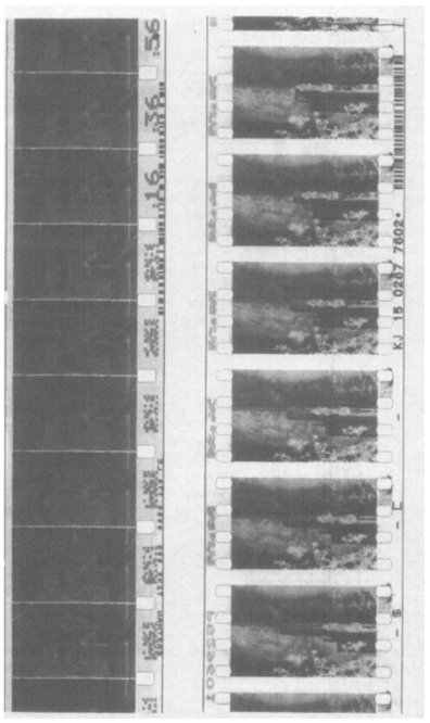
Figure 5.7 AatonCode recorded in-camera on the Super-16 format (a) and on 35 mm (b). There is no conflict with KeyKode®.
the camera controls the generation of the codeword to compensate for the acceleration and deceleration of the film. If the LED is in the magazine, and C-format code is being recorded, the microprocessor calculates the loop size (from the ballistics of the film movement) and compensates accordingly. The camera timecode generator is momentarily jam-synced to an external source of code. The code source should not be removed after syncing, however, as the oscillator driving the transport and gate mechanisms requires a continuous feed of external timecode to maintain synchronization with the associated audio recorder. Confidence of incoming code is achieved by either checking whether the LED is twinkling (if it can be seen) or by an external indicator LED. If the incoming code fails, the camera will revert to 24 fps. Figure 5.8 shows an example of ArriFIS code recorded on 35 mm film. During film/video transfer both SMPTE and KeyKode® are read and held on a microcomputer database, together with the videotape timecode. KeyKode® data can be put into the user bits of the videotape timecode. These data are later used by the controlling microcomputer to conform the EDL for the final cutting/process work. Figure 5.9 illustrates a typical arrangement.
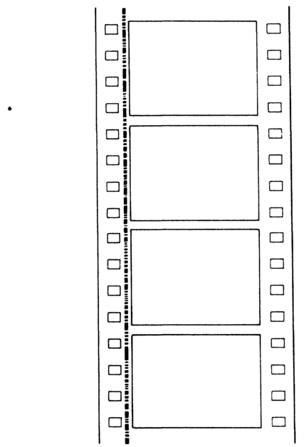
Figure 5.8 SMPTE code recorded in-camera by the ArriFIS system. There is no conflict with KeyKode®.
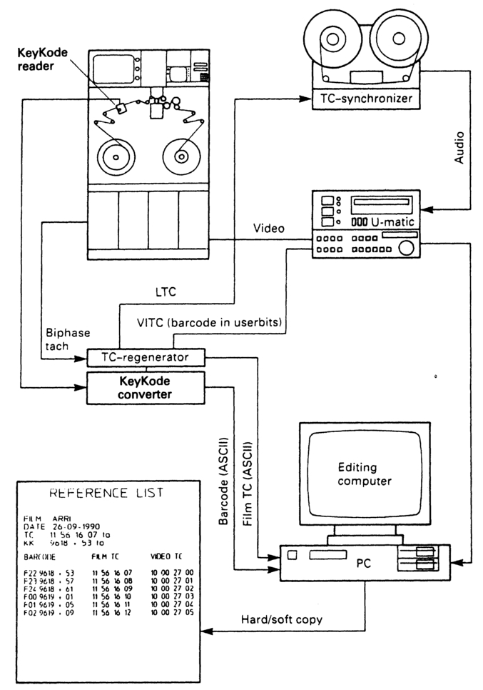
Figure 5.9 Film-to-video transfer involves KeyKode®, bi-phase (tacho) pulses and timecode. A small computer with a suitable database controls the process and logs the codes.
Machine-readable film timecodes
In 1988 the first discussions took place regarding a new edgeprint format, in 1990 the SMPTE proposed a standard for 'Manufacturer-printed latent image identification information' and in 1994 the standards were adopted as SMPTE 270 (for 65 mm film) and SMPTE 271 (for 16 mm film). This has been implemented by film stock manufacturers, for example the Eastman Kodak Company with its KeyKode® number system. The code is put on the film stock during manufacture as a latent image, which becomes visible when the film is developed. The code is both human- and machine-readable. The machine-readable code is a barcode to USS128 standard. This particular barcode is specifically intended for use with reflective media. Two characters are embedded in one symbol. The code can identify the film manufacturer and the type of film stock, as well as time data. The manufacturer's identification codes are given in Table 5.1. The Film Type Identifier Codes are included at the manufacturer's discretion. The time data are embedded in a ten-digit number which indicates film footage and roll number. Figures 5.10-5.12 illustrate the 16, 35 and 65 mm forms of the code, as implemented by the Eastman Kodak Company.
The various colours of the edgecode assist in distinguishing between human- and machine-readable information.
Barcode is cyan
Human-readable numbers are blue
Matching check symbols are blue
Manufacturer information is magenta
Table 5.1 KevKode® manufacturers' codes.
| Manufacturer | Code |
| Agfa-Gevaert N.V. | A |
| Eastman Kodak Company | K |
| Fuji Film Company | F |
| Other or non-designated | (nothing) |
Zero frame in the foot is the frame that is immediately above the zero frame mark. In the 35 mm format the code repeats every 64 perforations (every foot) with an identified mid-foot code 32 perforations after zero frame. In the 16 mm format the code increases by 1 every 20 perforations (6in). It is less wide than the 35 mm version in order to keep it out of the way of Aaton Time Code. The key number itself is numeric, and printed in both human-readable and barcode form. The key number is a 6-digit roll identification number and a 4-digit footage number. The barcode also contains the additional manufacturer and film type information mentioned earlier.
The barcode data consist of 16 digits, arranged into 8 characters: a 2
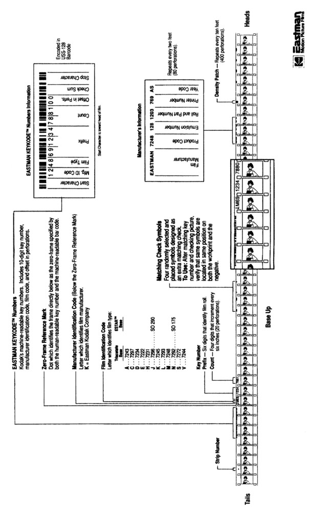
Figure 5.10 The Eastman 16 mm Edgeprint Format with KeyKode®. Courtesy of Eastman Kodak Company. © Eastman Kodak Company, 1991.
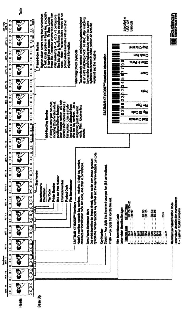
Figure 5.11 The Eastman 35 mm Edgeprint Format with KeyKode®. Courtesy of Eastman Kodak Company. © Eastman Kodak Company, 1991.
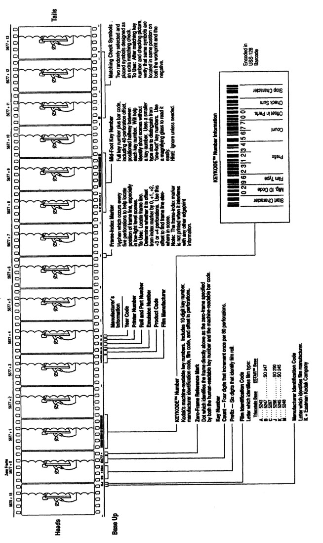
Figure 5.12 The Eastman 65 mm Edgeprint Format with KeyKode®. Courtesy of Eastman Kodak Company. © Eastman Kodak Company, 1991.
digit manufacturer's identification code, a 2-digit film type code, a 6-digit number (the 'prefix') to identify the roll, a 4-digit footage count, and a 2-digit offset (00 for the code at frame zero, 32 for the mid-foot code). The code is preceded by a start character. It is followed by checksum and stop characters. The checksum is the Modulo 103 sum of the start character and the weighted values of the 8 data characters.
Many manufacturers have developed equipment to both read the KeyKode® number system, and to convert it to IEC code (Figure 5.13). This facility permits the video off-line editing of film. The timecode can also be converted back to key number form again for the convenience of the negative cutter.
Film transfer to PAL video
Much film post-production is undertaken on videotape. This involves transfer of film to video at two separate points in the process: before video editing, and after video editing, before sound post-production. If the film
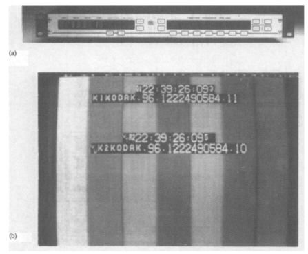
Figure 5.13 A timecode processor (a), which will display KeyKode®, TC generator path, TC signal type, and colour frame number (b), as well as performing a wide range of reprocessing and code translation functions. Courtesy Avitel Electronics Limited.
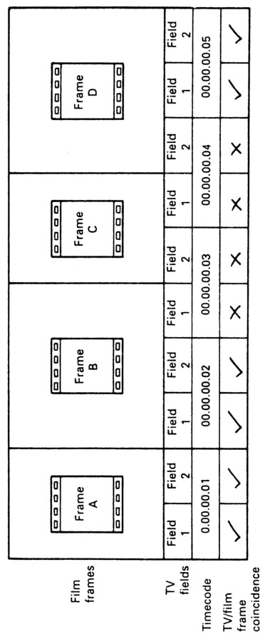
Figure 5.14 The relationship between 24 fps film and 30 fps video timecodes results in a 4 film frame/5 video frame sequence known as 3/2 pulldown. Frame A correlates exactly. Film frames B and D are recorded on three successive video fields. Film frame C is recorded on fields in different frames.
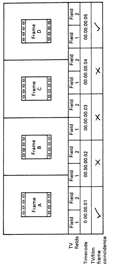
Figure 5.15 A linear 24/30 film /video transfer results in mixed film frame information on three out of five video frames.
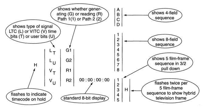
Figure 5.16 The film/video field/frame relationships that can be displayed on a picture monitor. Courtesy Avitel Electronics Limited.
and the accompanying audio are shot at 25 Hz frame rate there should be no problems with either pictures or sound transfer as long as everything is synced together. However, if the film has been shot at 24 Hz there can be problems. If the telecine/ video transfer is done at 25 Hz, the film will be running 4.1666...% fast. This can cause problems with some database management systems as they round up after a few decimal places, causing drift over time. The time discrepancies brought about this change in speed shift can be logged in the database of the controlling microcomputer or recorded in the user bits on the videotape. The sound will be running fast however, and particularly where music is concerned the discrepancy will be very audible.
A more elegant solution is to run the telecine at 24 Hz frame rate, locked to station syncs, and to make up the additional frames. Since telecine machines are working with optical images they can have RGB or component outputs, which means that sub-carrier phase is not a problem. An extra field can be added every twelve frames, the scans on the machine being modified accordingly, to maintain interlace. There will be short-term time discrepancies between timecode of film and real time, but these can be accommodated by a microcomputer and suitable database. The sound should either be transferred via a recorder locked to 50 Hz (the original tape running at 24 fps), or transferred to a machine (perhaps a digital sound station) which can run the sound at an equivalent 24 fps rate while being locked to 50 Hz In either case the 50 Hz reference is divided down to give a 25 Hz frame rate.
Transfer of film to video intended for digitizing into a non-linear editing system can be much simpler, but will vary according to the non-linear system employed, and the capability of the telecine to run at 24 fps. In this respect, later versions of data management systems, such as Aaton's Keylink are able to convert 24 fps recorded code into a time-correct 25 fps 625/50 code. Chapter 10 discusses the options in detail.
3-line VITC
In 1994 Aaton and Evertz proposed a 3-line encoding format that can be generated during film-to-video transfer. The code is able to carry the in-camera code, audio recorder code, in-camera date, camera ident and Aaton Tags, all recorded at the time of shooting, as well as video tape code (of the recording VCR), video reel ident (of the recording VCR), 3/2 pull-down code (see next section) and KeyKode®, all recorded at film-to-video-transfer. The first VITC line carries traditional VITC CRCC, the other two lines each have their own unique CRCC to prevent confusion with traditional VITC information. Although the positioning of the 3-line VITC block is up to the user, the manufacturers recommend the following:
| Block | 625/50 lines | 525/60 lines |
| 1 | 19 - 20 - 21 | 18 - 19 - 20 |
| 2 (optional) | 14 - 15 - 16 | 13 - 14 - 15 |
| 3 (White Flag) | 12 | 12 |
| (optional) |
The first line of a block is defined as that which lies closest to the vertical interval. The data are recorded in the three lines in the following manner:
| Time bits | User bits | CRCC | |
| 1st line | Videotape timecode | Aaton Tags or video reel ID | Normal |
| 2nd line | Pulldown and Keykode® | KeyKode® | Inverted |
| 3rd line | In-camera (production) or audio timecode | Audio user bits or in-camera date & ID | MS nibble inverted |
The first line of the 3-line VITC is encoded with normal VITC CRCC so that it can be accessed by timecode readers installed in existing VCRs. The CRCC in the second line is inverted (i.e. '1's and '0's are inverted), and the third line has the bits in the most significant nibble of the CRCC inverted to prevent confusion from existing VITC readers. The White Flag line can be used to identify the first field of a video frame that results from a new image transfer.
The generators of the codes are manufactured as 1-U high 19in rack mounted units by a number of manufacturers, including manufacturers of non-linear editors, and may also contain or access data management systems (such as Aaton's Keylink or Avid's Phoenix). The ability to transfer all relevant time- and film-footage codes to videotape has profound implications not just for post-production, but also for the way a film is shot. These are discussed in Chapters 8 and 10. Appendix 8 carries the details of the bit arrangements within 3-line VITC.
Film transfer via 3/2 pulldown
Film shot at 24 fps cannot be run at 30 fps because of the large speed discrepancy between the two rates. To overcome this, and to permit easy comparison between film frame and corresponding video field, as identified by timecode, additional fields have to be inserted in a known sequence. This process, known as '3/2 pulldown', is illustrated in Figure 5.14. As can be seen, the sequence repeats every four film and five video (and timecode) frames, a ratio of 24:30. As the initial sequence starts with film from 00 and timecode from 00 it is possible to identify each point in the sequence from the timecode. If the video is running at 29.97 fps (as it will be with colour) then the telecine will need to run at 23.976 fps. The short-term time discrepancies can again be handled by a microcomputer.
It is possible to transfer film to video without 3/2 pulldown by using an optical multiplex system (linear transfer). In this case the film frames are mixed together in various proportions in each video field (Figure 5.15), with each film frame being transferred to an average of 1.25 video frames. This mix of frames is less than satisfactory. If 3/2 pulldown and linear transfer methods are compared we can see that with 3/2 pulldown three in five video frames (A, B and D) each contain information from one single film frame; with linear transfer only two video frames (A and D) in five each contain information from one single film frame. Equipment is available to display the correlation between film and video frames and fields and to display that correlation within the picture area, together with the timecode (Figure 5.16).
Control of 4:3 scanning for the presentation of wide-screen films
Within the EBU, although there is no restriction on the use of user bits by any individual organization for the exchange of recorded programmes, some broadcasters have devised some uses for them which the EBU has documented and distributed for the benefit of its members. One use, devised by the French broadcaster TDF, concerns the control of video scanning of wide-screen feature films for transmission in the standard 4:3 aspect ratio.
There are two ways in which wide-screen (16:9) format film can be transmitted; either it can be sent in 'letterbox' display, with black bars above and below the picture, or a panscan display can be presented, where a full-height section of the 16:9 film frame fills the screen, but parts of the sides are lost. The displayed section can be moved around to preserve as far as possible the artistic composition of the film frames.
If the film is transferred, in 16:9 format, to videotape before playout, codes can be placed in the user bits to select which area of the original picture will be transmitted. This is called 'Panscan'.
The user bits in the LTC carry the control data because:
- LTC tracks are available on all current and proposed broadcast tape formats.
- The data can be edited independently of picture and sound.
The data are sent twice, on separate frames, because:
- LTC is not decoded until the end of the timecode word has been reached (at the end of the frame). This implies a delay in the picture while the scanning data are decoded.
- Sending scanning data in advance permits applications that involve special effects stores, or which require panscan data in advance of the picture.
Panscan data is sent both during the picture to which it applies, and 15 frames ahead of that picture, so also carries information about the current frame (f) and the following frame (f + 15) to which it refers. The data are sent in binary groups 1-5. Groups 1 and 2 carry information for current frame (f), groups 3 and 4 carry information for frame (f + 15), group 5 carries aspect ratio data flags. Table 5.2a-b gives the details.
Table 5.2a Allocation of panscan data in the timecode word.
| Bits | Information | Coding |
| 0-3 | Units of frames | IEC 461 |
| 4-7 | Binary group 1 | LSB of panscan data for picture N |
| 8-11 | Tens of frames, etc. | IEC 461 |
| 12-15 | Binary group 2 | MSB of panscan data for picture N |
| 16-19 | Units of seconds | IEC 461 |
| 20-23 | Binary group 3 | LSB of panscan data for picture N+15 |
| 24-27 | Tens of seconds, etc. | IEC 461 |
| 28-31 | Binary group 4 | MSB of panscan data for picture N+15 |
| 32-35 | Units of minutes | IEC 461 |
| 36-39 | Binary group 5 | Aspect ratio and panscan flag |
| 40-43 | Tens of minutes, etc. | IEC 461 |
| 44-47 | Binary group 6 | Reserved, set to zero |
| 48-51 | Units of hours | IEC 461 |
| 52-55 | Binary group 7 | Reserved, set to zero |
| 56-59 | Tens of hours, etc. | IEC 461 |
| 60-63 | Binary group 8 | Reserved, set to zero |
Table 5.2b Aspect ratio stored in binary group 5.
| Binary group 5 | ||
| Bit | Information | Coding |
| D3 | Unassigned | X |
| D2 | Panscan flag | 1: panscan data 0: no panscan data |
| D1 | Image aspect ratio for picture N+15 | 1: aspect ratio of image N+15 is 16:9 0: aspect ratio of image N+15 is 4:3 |
| DO | Image aspect ratio for current picture, N | 1: aspect ratio of image N is 16:9 0: aspect ratio of image N is 4:3 |
Table 5.3 Examples of panscan data stored as hexadecimal codes.
| Position | Shift Ree. 601 sample intervals | Code | MS nibble | LS nibble |
| Far left | -43 | -43 | D | 5 |
| Central | 0 | 0 | 0 | 0 |
| Far right | +44 | +44 | 2 | C |
Table 5.4 Allocation of panscan data in the binary groups.
| Data about frame | Binary group | |
| MS nibble | LS nibble | |
| N | 2 | 1 |
| N+15 | 4 | 3 |
Data are sent in eight-bit (byte) groups, by pairing binary groups. For each picture the data indicate the shift away from the centre of the picture in increments of ITU-R Rec. 601 colour-difference samples (approx. 148 ns) in 2's complement form (see Chapter 2). Accordingly, there are 43 increments left, one central position, and another 42 increments right, that define the shift in the scan. The value is coded as two hexadecimal numbers as Table 5.3 illustrates. In each binary group pair the LS nibble is carried in the lower number group, and the MS nibble in the higher number group as Table 5.4 illustrates.