CHAPTER 5
![]()
Diodes, Rectifiers, and Zener Diodes
Resistors can work properly without regard to “polarity.” That is, in a circuit a resistor can be wired either way. For example, you can desolder the resistor from the circuit and flip the resistor leads and solder them back into the circuit and the circuit should work the same.
In this chapter, we will look at some basic two-terminal semiconductors. These are devices that require proper attention to how their leads are wired because their terminal leads have polarities. If you reverse a semiconductor’s lead, chances are that the circuit will not work at all, not work well, or not work the same (e.g., symmetrically).
Diodes and Rectifiers
Devices that conduct electricity from one terminal to another, while not conducting electrical current when the terminals are reversed, are diodes and rectifiers.
Before we see this in action, let’s take a look at them in terms of types, connection terminals (e.g., cathode and anode), and schematic diagram symbols. See Figure 5-1.
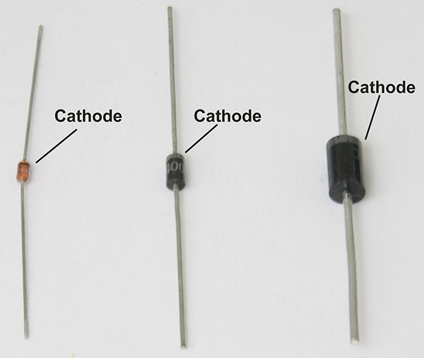
FIGURE 5.1 From left to right, a small signal diode (1N914), a 1 amp rectifier (1N4002), and a 3 amp rectifier (1N5401), all with cathode terminals as marked with stripes or bands.
The schematic symbol and terminal markings are shown in Figure 5-2.
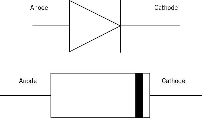
FIGURE 5.2 The schematic symbol of a diode or rectifier is shown on the top and its associated drawing with its cathode marking band is shown on the bottom.
There are two important characteristics in diodes and rectifiers: peak reverse voltage (PRV) and maximum conduction or forward current (IF).
Semiconductors such as diodes, rectifiers, transistors, and integrated circuits usually have a specific part number printed on them. This is different than the markings on a capacitor where there is the capacitance in micro farads or pico farads and the voltage rating.
Thus, you will not find a diode or rectifier that is marked “50 volts PRV, 1 Amp.” Instead, you will need to look up (e.g., via Google search or data books) the part number based on your diode’s PRV and maximum current rating. In this example, you will find a 50-volt PRV, 1-amp diode has a part number as 1N4001. If you need a 3-amp version at 50 volts, the part number will be 1N5400 (e.g., from On Semiconductor).
A typical small signal diode, such as a 1N914 or 1N4148, has a peak reverse voltage of about 75 volts to 100 volts and a maximum forward current of about 100 mA. Fortunately, in most low voltage circuits today, we do not worry much about the PRV since the power supply voltages generally work at less than 25 volts. However, even low-voltage circuits can damage small signal diodes if the forward current, IF, is exceeded. For example, if a 1N914 small signal diode is used as a power supply rectifier providing 500 milliamps, then the diode may be damaged by excessive diode current flowing into a circuit. When the diode is damaged, often it will conduct electricity both ways or directions like a low-resistance resistor, usually in the order of less than 1Ω.
To “correct” the situation, you can replace the 1N914 or 1N4148 small signal diode with a 1N4002 that is a 1-ampere, 100 PRV rectifier. Table 5-1 shows a short list of common small signal diodes and power supply rectifier/diodes with their PRV and maximum current rating.
TABLE 5.1 Silicon Small Signal Diode Part Numbers

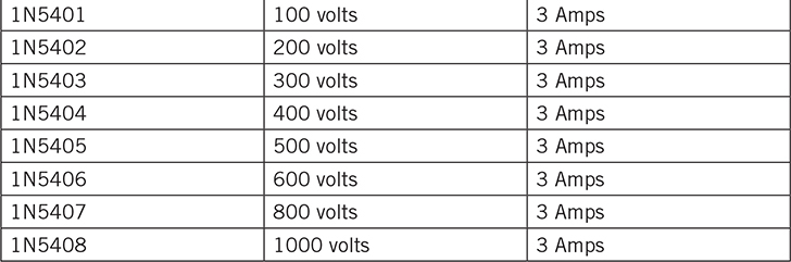
For large signal diodes or rectifiers, see Table 5-2, where these devices are used primarily for power supplies. Large signal diodes/rectifiers may also be used to protect other devices from high voltages, or to prevent circuits from accidental reverse voltages.
TABLE 5.2 Large Signal Diode/Rectifier Part Numbers

Large signal diodes such as the ones listed in Table 5-2 can be read relatively easily because the printing is gray or white on a black or dark epoxy diode body. For glass diodes such as the small signal diodes listed in Table 5-1, or other glass body diodes, the part numbers are imprinted on a shorter body, and the numbers are spanned out over three lines or rows. See Figure 5-3.
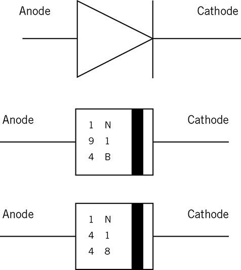
FIGURE 5.3 “Short body” small signal diodes, such as 1N914B and 1N4148, with their part numbers divided into a succession of three rows with two characters per row.
To identify these smaller glass diodes, we often need a magnifying glass or loupe to read their part numbers. See Figure 5-4.
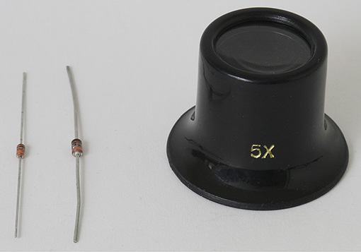
FIGURE 5.4 Glass diodes and a 5X magnifying loupe to read their markings.
One of the most common mistakes is putting in the wrong diode due to not reading its part number. Smaller glass diodes can include small signal diodes, but also include other types such as Schottky and Zener types. See Figure 5-5 for their schematic symbols compared to a standard diode.

FIGURE 5.5 Top: A standard diode with a straight bar for its cathode; Middle: A Zener diode with a “bent” cathode; Bottom: A Schottky diode—notice that the cathode resembles an “S” (for Schottky).
The drawings in Figure 5-5 are in the order of commonality. That is, we are more familiar with standard diodes first, then Zener diodes that are used primarily for establishing a specific voltage, and finally Schottky diodes that are used in situations where low forward voltage drop across the anode to cathode is required. We will look further into these two devices later. For now, let’s examine some voltage characteristics of standard diodes.
Forward Voltage Across Anode to Cathode and Reverse Voltage Effects
When an ideal diode is in forward conduction where a positive voltage is applied to the anode, this diode will transfer the same voltage to its cathode. Therefore, in an ideal diode there is no voltage drop across the anode to cathode when the ideal diode is conducting current. Put in another way, when an ideal diode is conducting current, it behaves like a wire. If the voltage is reverse biased where the anode voltage is negative, for example, the ideal diode will not pass any electricity and become an insulator or open circuit. The ideal diode has a forward voltage (VF) equal to zero volts.
However, standard silicon diodes have a forward voltage (VF) in the 0.5-volt to 0.7-volt range when measured across the anode to cathode leads. What this means is that when these common silicon diodes and rectifiers conduct in one direction, they develop a “loss” of about + 0.5 volts to + 0.7 volts across the anode to cathode terminals. The diode’s forward conduction happens when a positive voltage is applied to the anode with respect to the cathode voltage.
When a standard diode is reverse biased where the cathode to anode voltage is a positive voltage, there is essentially no current flow through the diode until the reverse bias voltage is equal to or exceeds the peak reverse voltage (PRV). Although essentially no current flows during reverse bias, the diode may leak through a very small amount of current, usually a micro-amp or less.
For example, a 50-volt PRV diode (e.g., 1N4001) will exhibit a very high resistance when the voltage is less than or equal to +50 volts across the cathode to anode leads. Beyond +50 volts, the 50-volt PRV diode will start conducting current.
When they are not conducting due to reverse voltage applied to the anode and cathode, the resistance is in the order of a million ohms. This reverse bias voltage occurs when the positive voltage is applied to the cathode with respect to the anode voltage, or put in another way, when the negative voltage is applied to the anode with respect to the cathode.
To illustrate forward conduction and reverse voltage non-conduction of a diode, see Figures 5-6 and 5-7.
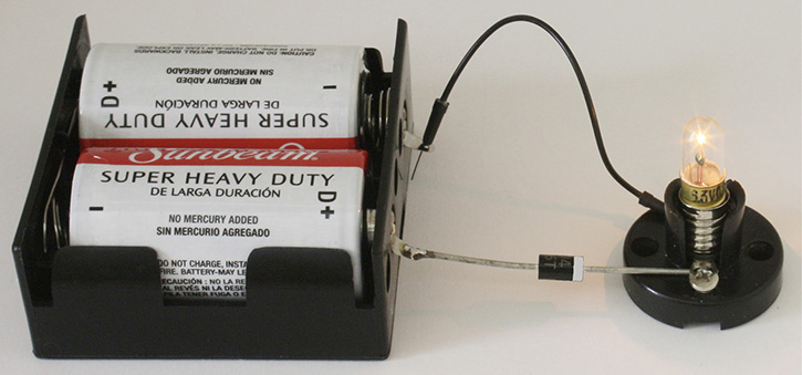
FIGURE 5.6 Positive terminal of battery is connected to the diode’s anode to enable the diode into forward bias conduction that supplies current to the lit lamp.
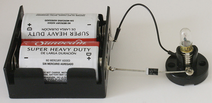
FIGURE 5.7 Diode connected in reversed bias mode with the battery’s positive terminal connected to the diode’s cathode. No current is flowing and the lamp is off.
In Figure 5-6, we see that a 1N5401 (3 amp) diode supplies current into the lamp.
Although a small signal 1N914 diode could have been used, the lamp’s current would have been close to the maximum current rating of the small signal diode. It’s always good to play it safe and use a higher current rating diode. Of course, the 1-amp 1N4002 device would have worked as well.
Now let’s look at what happens when the diode is reversed such that the battery’s positive terminal connects to the diode’s cathode lead. See Figure 5-7.
Testing Diodes and Rectifiers with Digital and Analog Volt Meters
With digital voltmeters (DVMs), we can determine whether a diode works or not by using the “diode” test feature that is available in most DVMs. See Figure 5-8.
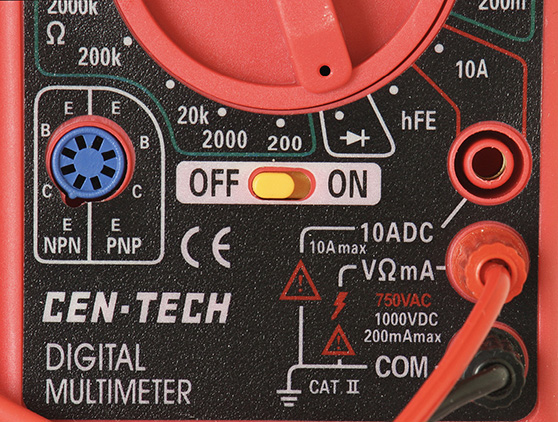
FIGURE 5.8 A typical DVM with its switch set to the “diode” test function that is represented by the schematic symbol of a diode.
We now will measure the forward bias voltage (VF) across the anode to cathode leads of two diodes, a small signal diode 1N914, and a large signal rectifier 1N4002 that has a 1-amp rating. The red positive test lead is connected to the anode and the black negative test lead is connected to the cathode. See Figure 5-9.
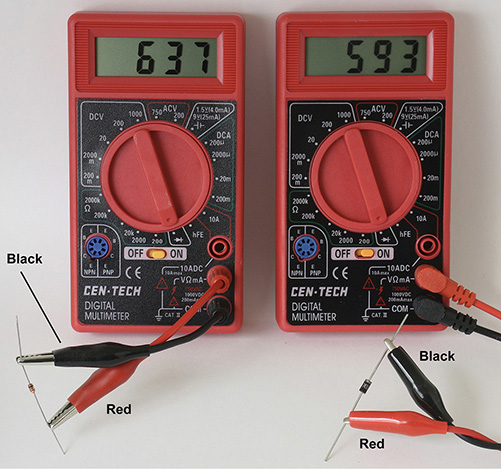
FIGURE 5.9 With the DVM’s test leads connected to the anodes via the red positive leads, and the cathodes connected to the black negative leads, we see that the forward voltage (VF) for the 1N914 is +0.637 volt, and the 1N4002 has voltage of +0.593 volt.
In general, higher current diodes or rectifiers will have lower forward voltages than a small signal version. One reason is that the higher current diodes and rectifiers must have very low equivalent series resistance. This is because when larger currents are flowing through a diode, any lossy resistance internal to the diode or rectifier will add as a forward voltage drop across the anode to cathode leads.
A bad diode will often have shorted out and exhibit the characteristics of a wire, which will conduct both ways. Also, when tested as shown in Figure 5-9, the resulting voltage will be < 10 mV or 0.010 volt instead of the voltage in the 500 mV to 700 mV range for a standard silicon diode.
When the test leads are reversed where the black test leads are connected to the anodes, and the red positive leads are connected to the cathodes, the DVMs will read a “1” and blank digits to show an “out of range” reading. This out-of-range reading means that the diodes connected this way look like a very high resistance resistor or an open circuit. See Figure 5-10.
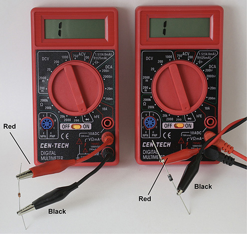
FIGURE 5.10 With the red test leads connected to the cathodes (e.g., striped side), the DVMs show an out of range display with only a “1” with blank digits elsewhere. This means that the diodes connected this way are like open circuits or insulators.
NOTE: With most DVMs, the red test lead is like supplying electric current from the positive terminal of a battery. However, this is not always the case with some analog meters.
Suppose we now try to test diodes with the DVM configured as an ohm meter? What we would expect is that in the forward conduction mode, the DVM’s ohm meter will display some resistance value. However, this may not be the case at all. See Figure 5-11 where we compare measuring a rectifier with an analog VOM (volt-ohm-milliamp meter) and a DVM.
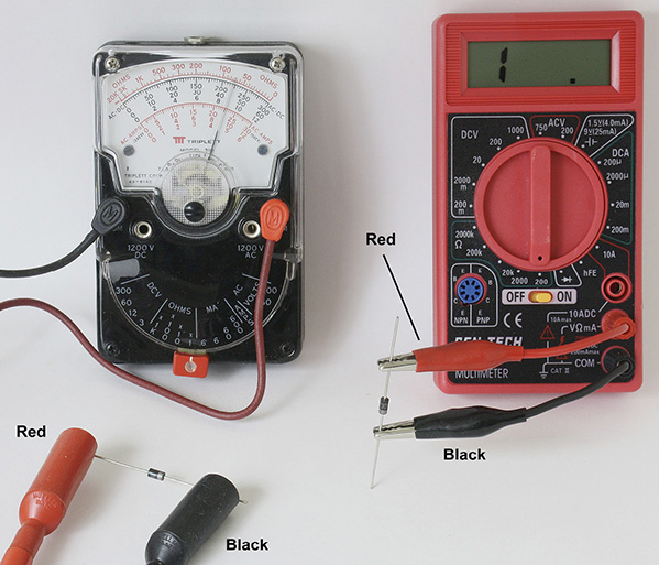
FIGURE 5.11 1N4002 rectifiers being tested on the left with an analog ohm meter that shows about 70Ω. The DVM on the right side shows an out-of-range condition signifying an open circuit, which is erroneous. Black leads of both meters are on the cathodes.
NOTE: The Triplett 310 analog ohm meter shows a 70Ω resistance with the diode at forward conduction when the positive test lead is connected to the anode. However, the actual resistance is lower because the diode has a forward voltage drop (e.g., 0.6 volt) that results in an inaccurate resistance reading. Usually, a reading in the forward conduction mode of less than 150Ω but more than 2Ω indicates that the diode is OK.
Many DVMs may not be able to test diodes in their ohm meter mode. Virtually all analog VOM meters will be able to test conduction of diodes in one direction while showing very high resistance in the reverse direction.
In Figure 5-11, the red positive test lead of the analog meter is connected to the anode of the diode-rectifier for testing forward conduction resistance. If the leads were reversed where the black lead is connected to the anode and the red lead is connected to the cathode, the meter’s needle will not move and stay on the side of the top scale, which would show infinite resistance.
With analog meters in the ohm meter mode, the red test lead does not always relate to the positive terminal of a battery. For those older meters made in United States, such as the Simpson 260 or the Triplett 310, 620, and 630 series, these analog VOMs have their positive test leads relating to the positive terminal of a battery.
However, some but not all analog VOMs elsewhere have their polarities reversed. That is, the black negative test lead is connected to the positive terminal of a battery. See Figure 5-12.
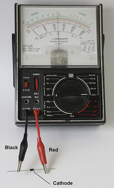
FIGURE 5.12 A “Micronta” analog VOM tested shows forward conduction (11.5Ω on top scale) with the negative black test lead connected to the rectifier’s anode.
Notice that the diode’s forward conduction occurs when Micronta meter’s negative test lead is connected to the anode. This is different from Figure 5-11 where the Triplett ohm meter shows forward conduction when its positive red test lead is connected to the anode of the rectifier.
Again in Figure 5-12, if the leads were reversed such that the red positive test lead is connected to the anode and the black test lead of the Micronta meter is connected to the cathode, then the diode will show essentially infinite resistance.
Testing a diode is normally done with analog VOM set to Rx1 (Ohms x 1) or Rx10 (Ohms x 10). Also, the actual resistance value for the diode in the forward conduction mode may vary from one analog voltmeter to another. The reason for this variation is because each meter may supply different test current or voltage to the diode. Usually, if the diode’s forward conduction resistance is less than 150Ω with Rx1 selected, the diode is OK.
Usually, a bad diode will short out and the resistance will read close to 0Ω. If you see this, then replace the diode. But also inspect or test other electronic components connected to the diode.
NOTE: Always test diodes with the power shut off and disconnect one lead of the diode from the circuit. If a diode is tested “in the circuit,” then an erroneous reading may occur. The reason is that other parts of the circuit connected to the diode may add a parallel resistance across the anode and cathode leads of the diode. This parallel resistance can cause the diode’s measurement in the reverse bias mode to show an unusually low resistance.
Schottky Diodes
Recall the schematic symbol for a Schottky diode has the cathode resembling an “S.”
Schottky diodes have lower voltage drop across their anode to cathode terminals compared to standard silicon diodes. With this lower voltage drop, Schottky diodes work well for lower voltage power supplies as to not “take away” some of the raw supply voltage. For example, if the raw supply is furnishing only 1.5 volts, a standard diode’s forward voltage drop (VF) is 0.55 volt that will subtract from 1.5 volts. As a result, about 0.95 volt will be at the output of the standard diode. A Schottky diode has a lower forward voltage drop, such as VF = 0.15 volt, and thus the output voltage will be 1.5 volts – 0.15 volt = 1.35 volt, a vast improvement over the 0.95 volt output from the standard silicon diode.
In general, you can replace standard silicon diodes with Schottky diodes, but be aware that the PRV rating may be lower. Schottky diodes are commonly used for switching power supplies that typically provide voltages below 24 volts DC but at very high currents.
For example, Table 5-3 shows the voltage ratings for the following 3-amp Schottky diodes. Note the lower PRV ratings compared to the 1N5400 series devices.
TABLE 5.3 Schottky Diodes Characteristics for the 1N5820 Series 3-Amp Devices
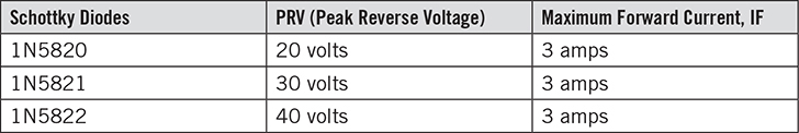
In contrast, the standard silicon 3-amp diode 1N5408 has a 1000 volt PRV.
Now let’s take a look at the forward conduction voltage drops of Schottky diodes. See Figures 5-13 and 5-14.

FIGURE 5.13 Testing for VF a Schottky diode (1N5822) on the left side, and a standard silicon diode (1N5402) on the right. Black leads of both meters are on the cathodes.
Note that the Schottky and silicon diodes look physically identical but the Schottky has a 0.153 forward voltage (VF) compared to a larger 0.533 voltage drop for the standard version.
Now let’s turn to small signal diodes. See Figure 5-14 for measurements of VF.
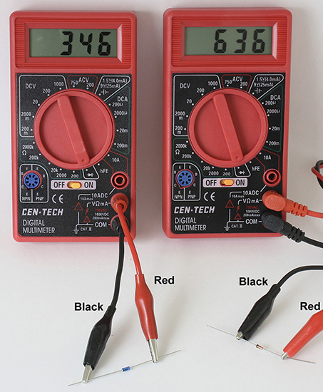
FIGURE 5.14 A Schottky small signal diode (1N5711) on the left and a standard small signal 1N914 diode on the right. Black leads of both meters are on the cathodes.
Note that the Schottky diode here has a 0.346-volt drop versus the 0.636-volt drop for the standard silicon 1N914 small signal diode.
In small signal circuits such as those with radio frequencies in a crystal radio, a standard silicon diode like the 1N914 or 1N4148 is unsuitable as the crystal detector because the radio frequency signals are weak, typically < 300 mV. A small signal Schottky is better but will still not pass through weaker radio signals in the crystal radio.
A better detector for a crystal radio is the germanium diode. It is based on very old technology (before 1950) and the germanium diode has a lower forward conduction voltage (VF), typically less than 300 millivolts. See Figure 5-15.
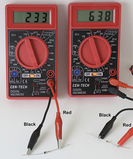
FIGURE 5.15 A germanium 1N34 diode on the left and a silicon 1N914 diode on the right. Note that the physical size of the germanium diode is much larger than the silicon device. Black leads on both meters are on the cathodes.
As we can see here, the germanium diode has a 0.233-volt drop versus the 0.638 volt in the silicon diode. Note that the Schottky diode measures 0.346 volt in Figure 5-14.
Also, beware of vendors selling “germanium” diodes that are of the size of a 1N914. These are unlikely to be (e.g., 1N34) germanium diodes. It should be noted that germanium diodes are generally packaged in larger (physical) sizes than small signal silicon diodes. However, a few vendors on the web may try to sell their germanium (e.g., 1N34) type diodes that are silicon and have the same larger size as a germanium diode. Thus, beware and (to be certain) always measure the forward diode voltage as shown in Figure 5-15.
For high frequency or radio frequency circuits (e.g., whose frequencies > 400 kHz), small signal diodes also require very low internal diode capacitance between the anode and cathode leads. The reason is that if there is a large capacitance across the anode and cathode, this large capacitance will cause signals to leak through the diode and bypass the diode as a signal detector.
For example, if we look back at Figure 5-14, then the 3-amp Schottky has a 0.152-volt voltage drop, even lower than the 1N34 germanium diode at 0.233 volt. So why not use the Schottky diode instead? The reason is that the 1N5822 Schottky rectifier has hundreds of pico farads of internal capacitance across the anode and cathode leads. This will cause the radio signal to bypass the 1N5822 rectifier, and thus the radio signal will not be demodulated correctly. However, if a radio signal’s frequency is in the 50 kHz or lower range, then the 1N5822 Schottky rectifier may just work.
A Brief Look at Zener Diodes
Zener diodes are very similar to standard silicon diodes in that they can pass current in one direction such as having a positive voltage applied to the anode. But this is not how Zener diodes are used. Instead, Zener diodes have a set or predetermined and accurate PRV (peak reverse voltage). This type of PRV in Zener diodes is known as the Zener voltage.
Some Zener voltages are:
• 3.3 volts
• 3.9 volts
• 4.3 volts
• 4.7 volts
• 5.1 volts
• 5.6 volts
• 6.2 volts
• 6.8 volts
• 8.2 volts
• 12 volts
• 15 volts
A Zener diode is also rated in wattage, which allows you to determine the maximum current flowing into it. Some of the common wattage ratings are 400 milliwatts, 500 milliwatts, 1 watt, and 5 watt.
The maximum Zener diode current, IZener = Wattage rating/Zener voltage
For example, if we have a 5.6-volt, 5-watt Zener diode (1N5339B), the maximum current is:
IZener = Wattage rating/Zener voltage
IZener = (5/5.6) amp = 0.89 amp = 890 mA
In another example, suppose we have a lower wattage Zener diode such as the 1N5237B, rated at 500 mW (0.50 watt) and 8.2 volts.
IZener = (0.50/8.2) amp = 0.061 amp = 61 mA
One thing to keep in mind as the Zener voltage is increased with the same wattage, the Zener diode’s maximum current goes down in proportion. But if the Zener voltage is decreased, then the Zener diode’s maximum current will increase given the same wattage rating.
TABLE 5.4 Example Maximum Zener Diode Current Based on Wattage and Zener Voltage
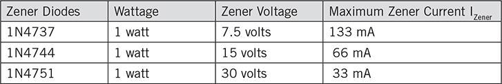
From Table 5-4 we first look at the 1N4744 Zener diode at 15 volts with a Zener current of 66 mA. If we decrease the Zener voltage by 2, which is a 7.5-volt Zener diode (1N4737), we have twice the Zener current at 133 mA. And increasing the 15-volt Zener voltage to 30 volts (1N4751) leads to half the Zener current at 33 mA.
In general, you should try to keep bias on the Zener diode to not more than 75 percent of the maximum Zener current. A good starting point is running the Zener diode at somewhere in the 15 percent to 50 percent maximum of IZener. For example, the 1N4744 device has a 66 mA maximum Zener current, and you can bias it at 50% or 33 mA.
Now let’s take a look at how various Zener diodes are labeled. See Figure 5-16.
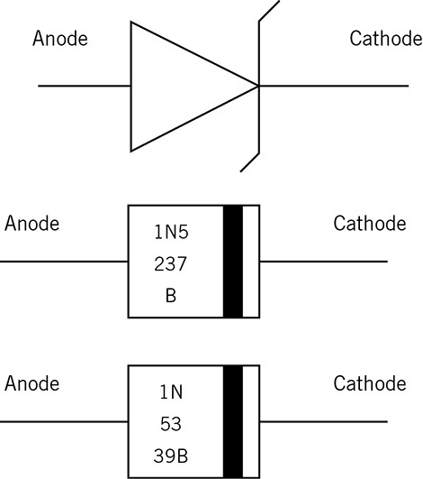
FIGURE 5.16 An example of a 0.50-watt 1N5237B Zener diode, and of a 5-watt 1N5339B Zener diode with their associated labeling.
Note in Figure 5-16 that the markings can span two or three lines for identifying the Zener part number. In the example of the 1N5237B, actually the first two lines (rows) will give your correct part number. You can usually ignore the suffix “B.”
For the 1N5339B, we see in Figure 5-16 that the part number is spanned over three lines (rows) to identify the Zener diode.
Just a reminder, a positive voltage greater than the Zener voltage will be connected to the cathode of the Zener diode. But the Zener current will be limited via resistor or a current limiting circuit.
So a pure voltage source such as a power supply or battery that has a higher voltage than the Zener voltage is NEVER connected across the Zener diode.
Now let’s look at two examples of Zener diodes in simple circuits. See Figures 5-17 and 5-18. Figure 5-17 shows that the red lead is on the anode.
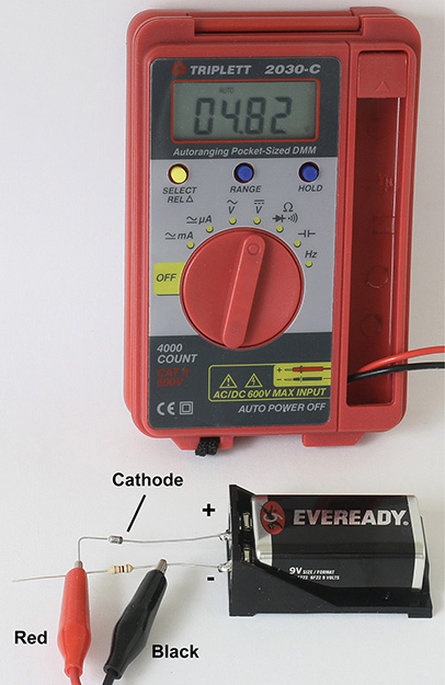
FIGURE 5.17 A 4.3-volt 1N749A, 400 mW Zener diode is connected in series with a resistor to drop or subtract 4.3 volts from the 9-volt battery.

FIGURE 5.18 A 4.3-volt 1N749A, 400 mW Zener diode on the left and a standard silicon diode, 1N914 on the right. Both black leads are on the cathodes.
In Figure 5-17 we see the 9-volt battery’s positive terminal connect to the cathode of the 4.3-volt Zener diode. Had this been a regular diode such as a 1N914, we would have a reverse bias condition and the voltmeter would have shown 0 volts. But because this is a Zener diode, it “breaks down” at about 4.3 volts and forms a 4.3 positive voltage from the cathode to the anode. This cathode to anode voltage, which is the Zener voltage, subtracts from the battery voltage when the voltage is measured from the anode of the Zener diode and the negative terminal of the battery. The resistor value shown is 1000Ω, and 4.82 volts is measured on the voltmeter. Note that 9 volts – 4.3 volts = 4.7 volts, which is approximately 4.82 volts. If the resistor’s value was changed from 1000Ω to 2000Ω or to 510Ω, the measured voltage would still be about 4.82 volts.
Let’s take a quick look at what happens if a Zener diode is accidentally reversed in wiring.
See Figure 5-18 for a Zener diode’s forward voltage, which is similar to a regular silicon diode.
As shown in Figure 5-18, both diodes are forward biased by having the red positive test leads connected to the anode of the Zener diode and standard diode. The Zener diode shows 0.789 volt while the standard small signal diode (1N914) shows 0.633 volt.
Thus, if you reverse a Zener diode’s connections you will get a voltage lower than the Zener diode voltage. For example, the 4.3-volt Zener diode provides about + 4.3 volts (across cathode and anode) when connected correctly, but will give only about + 0.789 volt when the leads are reversed.
Now let’s see if there is a better way to use the Zener diode. Figure 5-17 shows a series connection method of using a Zener diode. But it is not necessarily the best method to provide a stable voltage, or in an accident, a safe voltage. For example, suppose the 4.82-volt output voltage at the resistor is connected to a 5-volt logic circuit. If the Zener diode is inadvertently reversed in connection where the positive terminal is connected to the anode, the resistor will instead have 9 volts – 0.7 volt = 8.3 volts. If 8.3 volts is applied to a 5-volt logic circuit, most likely there will be damage. Also, if the 9-volt battery drops in voltage, the voltage at the anode of the Zener will drop as well below = volts. For example, suppose the 9-volt battery drains down to 8 volts. Then the output voltage in Figure 5-17 will be 8 volts – 4.3 volts = 3.7 volts. In the next example we will show a different circuit known as a shunt regulator that will maintain essentially constant voltage as long as the battery or power supply voltage is greater than the Zener diode voltage.
A better circuit is shown in Figure 5-19. Should the Zener diode be inadvertently connected in reverse or if the Zener diode shorts out, the voltage will be 0.7 volts or close to zero volts. This will be below the nominal 5 volts and will provide an “under voltage” that does not harm a circuit.
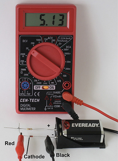
FIGURE 5.19 A 5.1-volt 1N751 400 mW Zener diode configured as a “shunt” regulator circuit that provides 5.13 volts as shown in the DVM. The red lead is on the cathode.
In Figure 5-19, the output voltage is taken across cathode to anode of the Zener diode. This output voltage is the Zener voltage. The series resistor (e.g., 1000Ω) is connected to the battery’s positive terminal and furnishes current to the Zener diode’s cathode. A positive voltage is provided at the cathode with the anode connected to the battery’s negative terminal. Figure 5-19 shows a shunt regulator circuit because the Zener diode is “shunted” across the output terminals.
Suppose the Zener diode is accidentally reversed. This accident results in the anode connected to the resistor and cathode connected to the battery’s negative terminal. The voltage will be the forward voltage of the diode, which is about + 0.7 volt. So, if a 5-volt logic circuit is connected to this shunt regulator circuit, there will be no damage to the circuit due to over voltage. And if the diode should short out, the voltage will be close to zero volts, which again will not damage the 5-volt logic circuit.
Some General Rules About Diodes
• They should not be wired in parallel for greater current capability because diodes bought off the shelf are not matched. If you measure the forward diode voltage from anode to cathode and the diodes are “matched” within 5 mV (e.g., Diode #1 = 0.608 volt, Diode # 2 = 0.603 volt), then they can be paralleled in close proximity to each other.
• If you buy the diodes in “tape” form, you have a much better chance of having matched diodes. The matched diodes can be used in circuits requiring nearly identical forward voltage characteristics and is not limited to paralleling diodes. See Figure 5-20 and be sure to double-check the diode’s forward voltages (VF) with a DVM. Both black leads are on the cathodes.

FIGURE 5.20 Two 1N914 diodes measured from a “tape” of 4 successive diodes with very close matching of VF within 5 mV. In this example the two diodes’ forward voltage readings of 0.641 volt and 0.642 volt are only 1 mV apart from each other.
So this ends a lengthier than normal chapter with introductions on standard, Schottky, and Zener diodes.
We will take a “breather” with a slightly shorter Chapter 6 that deals with light-emitting diodes (LEDs).