State machine diagrams are a familiar technique to describe the behavior of a system. Various forms of state diagrams have been around since the 1960s and the earliest object-oriented techniques adopted them to show behavior. In object-oriented approaches, you draw a state machine diagram for a single class to show the lifetime behavior of a single object.
Whenever people write about state machines, the examples are inevitably cruise controls or vending machines. As I’m a little bored with them, I decided to use a controller for a secret panel in a Gothic castle. In this castle, I want to keep my valuables in a safe that’s hard to find. So to reveal the lock to the safe, I have to remove a strategic candle from its holder, but this will reveal the lock only while the door is closed. Once I can see the lock, I can insert my key to open the safe. For extra safety, I make sure that I can open the safe only if I replace the candle first. If a thief neglects this precaution, I’ll unleash a nasty monster to devour him.
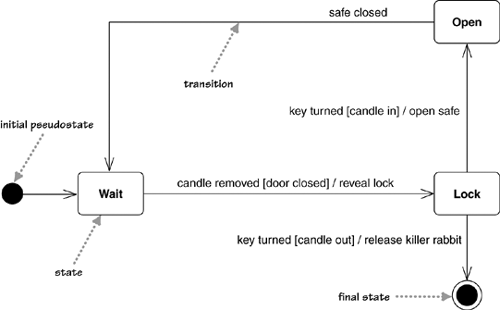
Figure 10.1 shows a state machine diagram of the controller class that directs my unusual security system.The state diagram starts with the state of the controller object when it’s created: in Figure 10.1, the Wait state. The diagram indicates this with initial pseudostate, which is not a state but has an arrow that points to the initial state.
The diagram shows that the controller can be in three states: Wait, Lock, and Open. The diagram also gives the rules by which the controller changes from state to state. These rules are in the form of transitions: the lines that connect the states.
The transition indicates a movement from one state to another. Each transition has a label that comes in three parts: trigger-signature [guard]/activity. All the parts are optional. The trigger-signature is usually a single event that triggers a potential change of state. The guard, if present, is a Boolean condition that must be true for the transition to be taken. The activity is some behavior that’s executed during the transition. It may be any behavioral expression. The full form of a trigger-signature may include multiple events and parameters. So in Figure 10.1, you read the outward transition from the Wait state as “In the Wait state if the candle is removed providing the door is open, you reveal the lock and move to the Lock state.”
All three parts to a transition are optional. A missing activity indicates that you don’t do anything during the transition. A missing guard indicates that you always take the transition if the event occurs. A missing trigger-signature is rare but does occur. It indicates that you take the transition immediately, which you see mostly with activity states, which I’ll come to in a moment.
When an event occurs in a state, you can take only one transition out of it. So if you use multiple transitions with the same event, as in the Lock state of Figure 10.1, the guards must be mutually exclusive. If an event occurs and no transition is valid—for example, a safe-closed event in the Wait state or a candle-removed event with the door closed—the event is ignored.
The final state indicates that the state machine is completed, implying the deletion of the controller object. Thus, if someone should be so careless as to fall for my trap, the controller object terminates, so I would need to put the rabbit in its cage, mop the floor, and reboot the system.
Remember that state machines can show only what the object directly observes or activates. So although you might expect me to add or remove things from the safe when it’s open, I don’t put that on the state diagram, because the controller cannot tell.
When developers talk about objects, they often refer to the state of the objects to mean the combination of all the data in the fields of the objects. However, the state in a state machine diagram is a more abstract notion of state; essentially, different states imply a different way of reacting to events.
States can react to events without transition, using internal activities: putting the event, guard, and activity inside the state box itself.
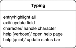
Figure 10.2 shows a state with internal activities of the character and help events, as you might find on a UI text field. An internal activity is similar to a self-transition: a transition that loops back to the same state. The syntax for internal activities follows the same logic for event, guard, and procedure.
Figure 10.2 also shows two special activities: the entry and exit activities. The entry activity is executed whenever you enter a state; the exit activity, whenever you leave. However, internal activities do not trigger the entry and exit activities; that is the difference between internal activities and self-transitions.
In the states I’ve described so far, the object is quiet and waiting for the next event before it does something. However, you can have states in which the object is doing some ongoing work.
The Searching state in Figure 10.3 is such an activity state: The ongoing activity is marked with the do/; hence the term do-activity. Once the search is completed, any transitions without an activity, such as the one to display new hardware, are taken. If the cancel event occurs during the activity, the do-activity is unceremoniously halted, and we go back to the Update Hardware Window state.
Both do-activities and regular activities represent carrying out some behavior. The critical difference between the two is that regular activities occur “instantaneously” and cannot be interrupted by regular events, while do-activities can take finite time and can be interrupted, as in Figure 10.3. Instantaneous will mean different things for different system; for hard real-time systems, it might be a few machine instructions, but for desktop software might be several seconds.
UML 1 used the term action for regular activities and used activity only for do-activities.
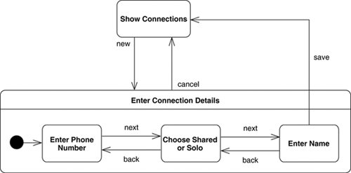
Often, you’ll find that several states share common transitions and internal activities. In these cases, you can make them substates and move the shared behavior into a superstate, as in Figure 10.4. Without the superstate, you would have to draw a cancel transition for all three states within the Enter Connection Details state.
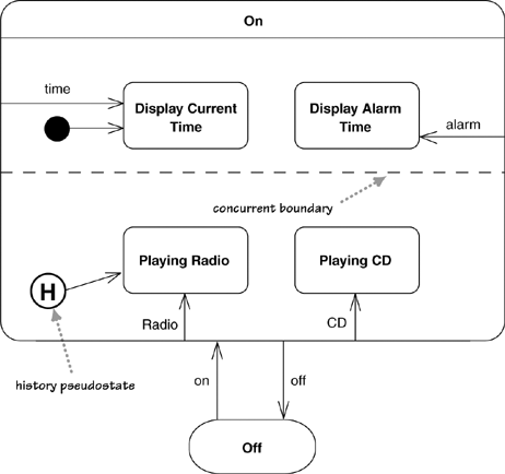
States can be broken into several orthogonal state diagrams that run concurrently. Figure 10.5 shows a pathetically simple alarm clock that can play either CDs or the radio and show either the current time or the alarm time.
The choices CD/radio and current/alarm time are orthogonal choices. If you wanted to represent this with a nonorthogonal state diagram, you would need a messy diagram that would get very much out of hand should you want more states. Separating out the two areas of behavior into separate state diagrams makes it much clearer.
Figure 10.5 also includes a history pseudostate. This indicates that when the clock is switched on, the radio/CD choice goes back to the state the clock was in when it was turned off. The arrow from the history pseudostate indicates what state to be in on the first time when there is no history.
A state diagram can be implemented in three main ways: nested switch, the State pattern, and state tables. The most direct approach to handling a state diagram is a nested switch statement, such as Figure 10.6. Although it’s direct, it’s long-winded, even for this simple case. It’s also very easy for this approach to get out of control, so I don’t like using it even for simple cases.
Example 10.6. A C# nested switch to handle the state transition from Figure 10.1
public void HandleEvent (PanelEvent anEvent) {
  switch (CurrentState) {
    case PanelState.Open :
      switch (anEvent) {
        case PanelEvent.SafeClosed :
          CurrentState = PanelState.Wait;
          break;
      }
      break;
    case PanelState.Wait :
      switch (anEvent) {
        case PanelEvent.CandleRemoved :
          if (isDoorOpen) {
            RevealLock();
            CurrentState = PanelState.Lock;
          }
          break;
      }
      break;
    case PanelState.Lock :
      switch (anEvent) {
        case PanelEvent.KeyTurned :
          if (isCandleIn) {
            OpenSafe();
            CurrentState = PanelState.Open;
          } else {
            ReleaseKillerRabbit();
            CurrentState = PanelState.Final;
          }
          break;
      }
      break;
   }
  }
}
The State pattern [Gang of Four] creates a hierarchy of state classes to handle behavior of the states. Each state in the diagram has one state subclass. The controller has methods for each event, which simply forwards to the state class. The state diagram of Figure 10.1 would yield an implementation indicated by the classes of Figure 10.7.
The top of the hierarchy is an abstract class that implements all the event-handling methods to do nothing. For each concrete state, you simply override the specific event methods for which that state has transitions.
The state table approach captures the state diagram information as data. So Figure 10.1 might end up represented in a table like Table 10.1. We then build either an interpreter that uses the state table at runtime or a code generator that generates classes based on the state table.
Obviously, the state table is more work to do once, but then you can use it every time you have a state problem to hold. A runtime state table can also be modified without recompilation, which in some contexts is quite handy. The state pattern is easier to put together when you need it, and although it needs a new class for each state, it’s a small amount of code to write in each case.
These implementations are pretty minimal, but they should give you an idea of how to go about implementing state diagrams. In each case, implementing state models leads to very boilerplate code, so it’s usually best to use some form of code generation to do it.
Table 10.1. A State Table for Figure 10.1
Source State | Target State | Event | Guard | Procedure |
|---|---|---|---|---|
Wait | Lock | Candle removed | Door open | Reveal lock |
Lock | Open | Key turned | Candle in | Open safe |
Lock | Final | Key turned | Candle out | Release killer rabbit |
Open | Wait | Safe closed |
State diagrams are good at describing the behavior of an object across several use cases. State diagrams are not very good at describing behavior that involves a number of objects collaborating. As such, it is useful to combine state diagrams with other techniques. For instance, interaction diagrams (see Chapter 4) are good at describing the behavior of several objects in a single use case, and activity diagrams (see Chapter 11) are good at showing the general sequence of activities for several objects and use cases.
Not everyone finds state diagrams natural. Keep an eye on how people are working with them. It may be that your team does not find state diagrams useful to its way of working. That is not a big problem; as always, you should remember to use the mix of techniques that works for you.
If you do use state diagrams, don’t try to draw them for every class in the system. Although this approach is often used by high-ceremony completists, it is almost always a waste of effort. Use state diagrams only for those classes that exhibit interesting behavior, where building the state diagram helps you understand what is going on. Many people find that UI and control objects have the kind of behavior that is useful to depict with a state diagram.
Both the User Guide [Booch, UML user] and the Reference Manual [Rumbaugh, UML Reference] have more information on state diagrams. Real-time designers tend to use state models a lot, so it’s no surprise that [Douglass]) has a lot to say about state diagrams, including information on how to implement them. [Martin] contains a very good chapter on the various ways of implementing state diagrams.
