One of the most significant new features in UML 2 is the ability to hierarchically decompose a class into an internal structure. This allows you to take a complex object and break it down into parts.
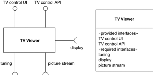
Figure 13.1 shows a TV Viewer class with its provided and required interfaces (page 69). I’ve shown this in two ways: using the ball-and-socket notation and listing them internally.
Figure 13.2 shows how this class is decomposed internally into two parts and which parts support and require the different interfaces. Each part is named in the form name : class, with both elements individually optional. Parts are not instance specifications, so they are bolded rather than underlined.
You can show how many instances of a part are present. Figure 13.2 says that each TV Viewer contains one generator part and one controls part.
To show a part implementing an interface, you draw a delegating connector from that interface. Similarly, to show that a part needs an interface, you show a delegating connector to that interface. You can also show connectors between parts with either a simple line, as I’ve done here, or with ball-and-socket notation (page 71).
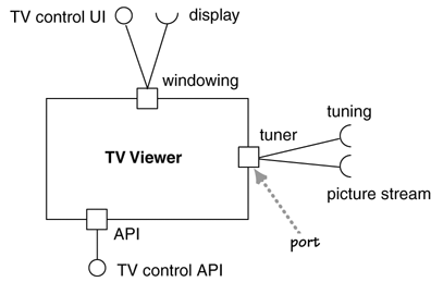
You can add ports (Figure 13.3) to the external structure. Ports allow you to group the required and provided interfaces into logical interactions that a component has with the outside world.
Composite structures are new to UML 2, although some older methods had some similar ideas. A good way of thinking about the difference between packages and composite structures is that packages are a compile-time grouping, while composite structures show runtime groupings. As such, they are a natural fit for showing components and how they are broken into parts; hence, much of this notation is used in component diagrams.
Because composite structures are new to the UML, it’s too early to tell how effective they will turn out in practice; many members of the UML committee think that these diagrams will become a very valuable addition.


