One of the reasons for using patterns and blueprints when developing a use-case model is to speed up the development of the model. With predefined use-case models, it is also possible to provide standard realizations of these models. This gives a kick-start when designing the system—that is, when mapping the use cases onto classes. Another effect of providing such mappings is that it becomes clear what the effects of different modeling decisions in the use-case model are in the subsequent models.
In Part III, “Use-Case Patterns,” and Part IV, “Use-Case Blueprints,” we have therefore included ideal class models—models that are independent of implementation technologies. These models present initial attempts at the classes needed to perform the use cases. This chapter provides the background you need to understand such ideal class models, or analysis models as they are often called.
You can find an introduction to class modeling and object orientation in Object Technology: A Manager's Guide, by D. Taylor (Addison-Wesley, 1998) and in Object-Oriented Software Engineering: A Use-Case Driven Approach by I. Jacobson et al. (Addison-Wesley, 1993).
Use cases model how a system is to be used. However, they do not capture how the system is structured internally in terms of classes, components, subsystems, and so forth. The internal structure is stated in a class model, such as an analysis model or a design model, modeling the realization of the use-case model. Usually the difference between these two kinds of models is that an analysis model describes how the system ideally ought to be structured so that it can be easily maintained, whereas a design model describes how the system is actually structured.
The analysis model expresses the platform-independent, ideal design of the system and can therefore be given a straightforward structure. In contrast, the design model has to be adjusted to constraints imposed by performance requirements, implementation standards, security requirements, existing code, volumes to be handled, what can be implemented efficiently in the programming language at hand, and so forth. In some situations, the maintainability might have to be partly sacrificed to meet the design constraints.
There is a never-ending discussion whether to use an analysis model when developing a system. Many agree, and we certainly share their opinion, that it is wise to develop the design model in two steps. The first step involves preparing an initial version of the model not taking into account implementation constraints. The goal here is to prepare a model that is resilient to future changes and additions. For this reason, this task is sometimes referred to as robustness analysis (Jacobson et al. 1993; Rosenberg and Scott 1999). In the second step, this ideal model is adjusted and adapted to the implementation environment at hand, which results in an ordinary design model.
In this sense, the developers will actually have an analysis model at some stage in their work (even if the work is done incrementally). The remaining question to answer is this: Should the analysis model be maintained, be discarded after the design model has been produced, or be refined and transformed into a design model? Different persons have different views on the subject; we only want to stress that we do not think that the development team should have the final say in the matter. The product owner ought to decide which types of models should be developed and maintained, because he or she is responsible for the maintenance and the enhancement of the system.
The following sections first describe what different kinds of classes we use in the analysis models, and then describe how the mapping from use cases onto analysis classes is expressed.
Analysis classes are ordinary classes; they declare the structure and the behavior of the instances, or objects, that appear in the analysis model. However, the declaration is often not as detailed and explicit as are those for design or implementation classes. The focus is more on the responsibilities of the instances of the classes than on how these responsibilities are to be realized. Typically, the behavior is described in ordinary text (rather than in algorithms expressed in a language with precise semantics such as a programming language). Furthermore, parameter lists are seldom complete (if they exist at all), and rather than following an implementation standard the name of a signature focuses on understandability. Similarly, many of the details about the information expressed as attributes in the classes and associations between the classes are abstracted away. All of these details must be provided at some point, but most of them can safely be left to the design model, thereby preventing wasted time and effort in making preliminary decisions in the analysis model that later have to be changed in the design model.
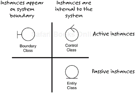
We favor a paradigm with three kinds of analysis classes: entity class, control class, and boundary class, each with its own notation icon (see Figure 15.1). We originally used this paradigm in OOSE (Jacobson 1993), and it is now used in other books and processes (Jacobson, Booch, and Rumbaugh 1999; Rational Software Corporation 2003; Rosenberg and Scott 1999). The idea is to look at the system in terms of three dimensions, which helps to keep each class more focused on one subject—a class should not be an assembly of independent things; remember that maintainability is a primary goal of the analysis model. The advantage of organizing the system according to these dimensions is that the classes can often be modified independently of each other. Hence, a class focused on displaying information is not modified if the procedure of how to perform a task is modified. (Of course, the world is seldom ideal, so at times a fourth concept might also be useful: service package, which is a package grouping modeling elements that model a whole service offered by the system. A modification of that service should only affect the classes in the corresponding service package.)
If you are not interested in using these kinds of classes, they can simply be replaced, in this chapter as well as in the pattern and blueprint descriptions, with ordinary nonclassified (nonstereotyped) UML classes.
The meanings of these kinds of classes are as follows (see Figure 15.1):
Entity class—. Models a concept managed inside the system. The focus of the entity classes is on the information the system needs about various concepts, but they also contain the behavior relevant for these concepts. Instances of entity classes are passive in that they provide other instances in the system with information, but they do not initiate communication with other instances than entity objects. The instances usually live longer than a use-case instance (they are often said to be persistent), but longevity is not a firm requirement. One entity class usually participates in multiple use cases and one entity object in multiple use-case instances.
Control class—. Models a task or a job to be performed in the system; it coordinates what takes place in a use case. The task originates from one or a few use cases in which the task is performed. Instances of these classes are active in the system because they perform the tasks and coordinate the actions in the system. The instances normally live only during the lifetime of one use-case instance; they are said to be transient. A control object usually participates in one use-case instance, but a control class may participate in the realizations of a few use cases.
Boundary class—. Models a transformer of the interaction between the interior of the system and the system's environment; the boundary classes appear only on the system boundary. This implies that communication between actors and the system is handled by instances of boundary classes. Instances of a boundary class are normally active, because they initiate actions in the system. The instances can both be short-lived and long-lived. In the realization of one use case, there must be at least one boundary class for each actor associated with the use case. However, the same boundary class may participate in the realization of multiple use cases, and one boundary object may participate in multiple use-case instances.
The properties of the different kinds of analysis classes imply that associations connected to entity classes should be navigable only to the entity class, but not from an entity class to a boundary class or a control class. (Passive instances should not initiate interaction with active instances.) However, entity classes may have associations with other entity classes, and these associations may be navigable in both directions.
Classification of classes like this is expressed with stereotypes in UML. This implies that all these three kinds of analysis classes have all the features of ordinary classes, such as attributes and operations, but they have been given specialized purposes as well as icons of their own.
The use-case model and the analysis model model different aspects of the same system. Therefore, in the analysis model it must be possible to perform all the usages of the system expressed in the use-case model; otherwise, these two models are not harmonized. (In fact, the reverse is also a requirement, although this is seldom mentioned: All the ways the system can be used according to the analysis model must be modeled as use cases in the use-case model.) For each use case, we create a use-case realization that states what roles are to be played by instances, or objects, of the classes in the analysis model when they cooperate to jointly perform an instance of the use case. Such a use-case realization is usually documented in what in UML is called a communication diagram (previously called collaboration diagram) or a sequence diagram, stating what participants take part and what their interactions will be when performing the use-case instance.
Assume that we have a task management system where work tasks are registered. The registration of a task includes what is to be done, when to do it, and any other information needed. At some other point in time, on a command, the system retrieves the registered work tasks that are to be performed at this moment in time, and these selected work tasks are then executed by the system (see also Chapter 28, “Future Task”).
The realization of the
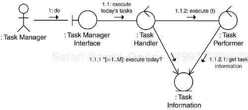
Perform Taskuse case—the realization of the latter use case described previously—consists of a set of roles that are played by a collection of objects when they together perform one instance of thePerform Taskuse case (see Figure 15.2).Figure 15.2. A communication diagram presenting the use-case realization of the
Perform Taskuse case.Figure 15.2 shows the realization of the
Perform Taskuse case. Because the use case starts when theTask Managercauses an external event (in this case, by giving a command to execute the relevant work tasks), there must be a boundary object between the actor and the rest of the system. Therefore, we introduce theTask Manager Interface. An object of this boundary class will transform the external event into an internal stimulus sent to a control object responsible for identifying what work tasks are to be performed at this moment in time. This control object is an instance of the classTask Handler, which models how the retrieval of tasks is performed.We can conclude that the system also needs to handle information about the work tasks, so we identify an entity class, the
Task Informationclass. After theTask Handlerobject has identified what work tasks are to be performed, these work tasks will be executed. Because this is another job to be performed within the use case, we identify another control class,Task Performer. (That it is another control class can easily be seen by just analyzing the cardinalities: There is one instance identifying the work tasks, but there are many work tasks to be executed in each use-case instance.) TheTask Performeris responsible for executing a work task, so it will contain a description of how this is done. Any task-specific information it will need for the execution is to be found in its instance ofTask Information.
Multiple use-case realizations can be used when realizing a use case. If some of the alternative flows depart significantly from the basic flow—that is, if a partly different collection of roles is used—the realization of the alternative flow is best captured in a separate use-case realization. Together, these two use-case realizations then realize the complete use case. Furthermore, nothing prevents using multiple communication or sequence diagrams when documenting a use-case realization. If, for any graphical reason, the diagram becomes difficult to read, split it into two or more diagrams; by doing so, you will make the use-case realization more easily understood by the reader.
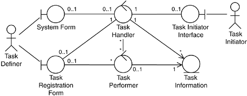
A more lightweight alternative to producing communication or sequence diagrams for the use-case realizations is to leave out the dynamics from the diagram and let it show only the roles the objects are to play and their relationships (see Figure 15.3). The diagram may be complemented by one or a couple of sentences written for each participant, describing its responsibility in the performance of the use case. In this way, the dynamics are described textually, which is often preferred for use-case realizations during analysis; the details of the communication being excluded to be worked out as part of the design work.
The use-case realizations form a basis for identification of the classes. Each realization identifies what roles are to be played by instances when they jointly perform an instance of the realized use case and hence what requirements the use case poses on the instances. By analyzing one realization, or a group of related realizations, we can identify classes or associations that are needed in the analysis model, or features that have to be added to the description of the existing analysis classes. Based on this information, we can extend our model with new classes, new associations, and new features so that it will be possible for the analysis model to perform the realized use case.
Sometimes it becomes necessary to go back and modify some of the use-case realizations because they might impose contradictory requirements on the analysis model, but that is at least a localized problem. We will not have to start all over again. Nevertheless, it is necessary to iterate back and forth between the use-case realizations and the analysis classes, all the time making sure that the use-case realizations and the use cases synchronize. When both sides have stabilized, we can describe the classes in more detail and continue with the design model.
Experience shows that it is most helpful to prepare a class diagram for each use case, presenting the static structure of all the classes that somehow participate in the realization of the use case. This is particularly true when multiple sequence diagrams are used to document the use case's realization. In this way, the reader will get an overview of the subset of the classes in the analysis model that is relevant for this use case. In the early days, we called such a diagram a VoPO, an acronym for View of Participating Objects, because we then used the term object in a much broader sense than today (the term meant both classes and instances). Today, a more proper acronym would be VoPC, which obviously has not caught on, probably because it is hardly pronounceable.
In the descriptions of the patterns and modeling problems in the next part of this book, we have chosen to include an analysis model consisting of the classes needed for realizing the use cases. We have also added a textual description of how the classes are used in that context.


