The system is to include or make use of an already existing system.
Characteristics: Common. Basic solution.
Keywords: Embedding existing system, existing system, incorporating existing system, old system, using existing system.
This blueprint captures the situation where the system includes a legacy system as a part of it, which implies that the legacy system is not structurally visible in the use-case model. However, it appears in the description of the use cases.
This blueprint is preferred when there should be no explicit interaction with the legacy system in the use-case model. Instead, the parts of the use cases that are performed in the legacy system are described briefly in the use-case descriptions; that is, the behavior and the information of the legacy system are described at a higher level of abstraction than are the other parts of the system.
When a new system is to be developed, there is often already an older system that partly covers the needs of the new system. If the old system is to be replaced by the new one after it has been developed, this causes no problem. However, the situation is more complicated if the transition from the old to the new system will take place over a sequence of versions of the new system—that is to say, if the two systems will live in parallel for a while.
How can we incorporate the old system in the new system, or, from our point of view, how can we incorporate it in the use-case model? In principle, there are two ways to handle the old system: Either we keep it outside the new system or we wrap it up inside the new system where, hopefully, it will eventually be replaced by a new, possibly better implementation.
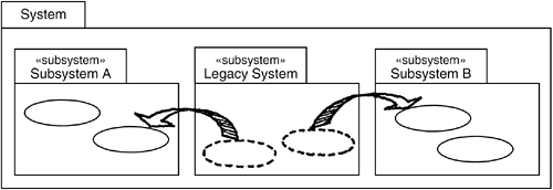
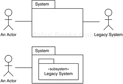
In the former case, we treat the existing system as an actor to the new system, and in the latter, we treat it as a subsystem (see Figure 30.1). Several factors have to be considered when deciding which alternative is preferable, some of which are discussed here.
Figure 30.1. A legacy system can either be modeled as an actor to the new system or as a subsystem inside the new system.
One important factor is whether other systems and users are to continue to use the old system as is, or whether it is to be replaced by the new system altogether. If others are to continue to use the old system, it must be treated as an actor to the new system because it must be possible to continue using its functionality independently of the new system. In this case, the Legacy System: Separate blueprint is applied and the old system is modeled as an actor that is given the same name as the old system, as is shown in the upper part of Figure 30.1. If the old system consists of clearly distinguishable parts that are used independently, the old system might even be modeled as a collection of actors, each of them given the name of the part it represents.
When it is not necessary to access the old system directly, it is better to apply the Legacy System: Embedded blueprint and treat the old system as a subsystem in the new system. One advantage of this approach is that it enables gradual replacement of the old system. This means that when developing new versions of the new system we can move functionality from the old subsystem (that is, stop using that functionality) to other subsystems that will implement the corresponding functionality. Eventually the subsystem modeling the old system can be removed completely as all its functionality and information are covered by other parts of the new system (see Figure 30.2).

Figure 30.2. In each new version of the new system, functionality is moved from the subsystem modeling the legacy system (Legacy System: Embedded) into other subsystems, so that it can finally be removed.
In both cases, it is important that a well-defined interface be defined for the old system, where we define how it is to be accessed by the new system. Failure to do so will imply that the boundaries of the two systems will be undefined, that it will be difficult to access the old system in a homogeneous way, and that the systems might eventually blend together into one cemented blur.
When the legacy system is represented by an actor, this interface is often realized by a separate component between the actor and the other parts of the new system. All interaction with the actor must go through this interface component, which transforms the interaction and transferred information to suitable formats and signals.
In the encapsulation case, we instead create a subsystem enclosing the legacy system, acting as a wrapper and defining all the operations that can be applied to the legacy system.
How, then, do we express the use cases when we are dealing with a legacy system? In the actor alternative (the Legacy System: Separate blueprint), the use cases must include the sending and the receiving of messages to and from the actor modeling the old system. The interaction with the old system must be explicitly stated; that is, it must not be hidden or abstracted away because a reader would then easily misunderstand the use case, thinking that the functionality of the old system is captured by the new system. It is imperative to use phrases like this:
Or, in the other direction:
We need not mention that the information or the requests must be transformed into other formats. This transformation is handled by the interface and will not add to the understanding of the use case. Furthermore, how the old system performs an operation, or stores or retrieves relevant information, should not be described in the use case because this is handled outside the system that is modeled by the use cases.
This means that in general the use cases of the new system are modeled and described as ordinary use cases. However, it might be useful to give a slightly more thorough description of what the actor modeling the legacy system does in the interaction with the use cases than is normally done for actors. If this information is left out, the user might find it difficult to understand the service modeled by the use case because several important parts are performed by an actor and not by the use case.
When the old system is wrapped inside a subsystem of the new system (the Legacy System: Embedded blueprint), the use cases of the new system should be described as normal use cases. The only difference is that the description of the parts of the use cases that take place inside the legacy subsystem can be expressed at a more abstract level than usual because these parts have already been implemented and are not to be developed. The description of these parts should cover only what is needed for a reader to understand what they accomplish, and exclude other details.
This is different from an ordinary use-case description where the whole use case should be described at a uniform level of abstraction. It is advisable to explicitly mention in the use-case descriptions that a certain part of the behavior is performed in the legacy subsystem, because this explains the difference in level of detail and abstraction in the description. How the transformation of information inside the legacy subsystem is to be performed should not be captured in the description of the use cases, nor how the interaction with the legacy subsystem is to be performed. This is design information, and should be described within the wrapper.
When a part of the legacy subsystem is to be enhanced and therefore moved to and implemented by another subsystem, the corresponding parts of the use cases must also be enhanced so that they capture the new requirements. These parts must then be expressed at a more detailed level—that is, at the same level as the rest of the use cases—because the modified parts are now to be used for developing new realizations (see the following example).
This section provides an example of wrapping a legacy system inside a subsystem defined in the new system—that is, the Legacy System: Embedded blueprint. (Handling the legacy system as an actor as in the Legacy System: Separate blueprint does not imply anything specific to the use-case descriptions. All interactions are described as usual interactions with actors.)
Two versions of the flow description of one use case are provided. The first one uses the existing functionality of the legacy system. In the second version, some of this functionality has been replaced by an enhanced procedure to be implemented in a new subsystem.
The example is a warehouse system for registering orders to be shipped to customers. The warehouse has a legacy system for scheduling deliveries at a first-come, first-served basis. The first version of the new system is to use the old scheduling system (the legacy system) for scheduling new orders. In the second version of the system, the scheduling of deliveries will be more intelligent (for example, so that deliveries to addresses close to each other will be handled in one shipping).
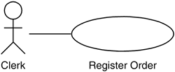
The following section presents the two versions of the use case Register Order (see Figure 30.3). In the first one, the legacy system is used, which implies that the planning of the deliveries is described at a high level of abstraction. The second version includes an enhanced planning procedure of the shipment, so the corresponding part of the flow in this version is given at the same level of abstraction as the rest of the flow.

Figure 30.3. The Clerk registers new orders in the system. In the first version of the system, the scheduling of the deliveries of the orders is done using the functionality of the legacy system. In the second version of the system, a new algorithm is used.
The Business Rules and the CRUD patterns might also be useful in this example, as might the Future Task blueprints.
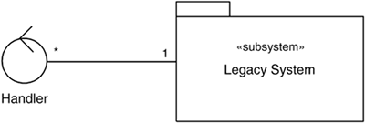
The analysis model for a system using a legacy system depends on how the legacy system is modeled. In the Legacy System: Embedded blueprint (see Figure 30.4), the legacy system is wrapped inside a subsystem in the system. Therefore, all interaction with the legacy system is expressed as interactions with that subsystem. Here the content of the new system is represented by a control class, but it can, of course, be any kind of class in the new system.

Figure 30.4. In the analysis model of the Legacy System: Embedded blueprint, the interaction with the legacy system is expressed as interaction with the subsystem enclosing the legacy system.
In the Legacy System: Separate blueprint, where the legacy system is modeled as an actor, a boundary class, Legacy Interface, is introduced, which is to transform the different data formats and signals between the new system and the legacy system (see Figure 30.5). This boundary class will often correspond to a large chunk of code, but there is no reason to model it in detail during the analysis because its responsibility is quite obvious. The details are left to be worked out during design.


