Structure the use-case model so that each use case is defined within one layer, and use relationships between the use cases in different layers to allow use-case instances to span multiple layers.
Characteristics: Common in mid-size and large systems. Advanced solution.
Keywords: Accessing lower layers, application-specific functionality, dependency direction, directed dependency, domain-specific functionality, level of abstraction.
In each of the Layered System patterns, there are two packages modeling two layers, and a package import relationship from the package representing the upper layer to the package representing the lower layer. The relationship implies that the (public) contents of the lower-layer package become available inside the upper-layer package. All relationships between elements defined in different layer packages are defined within the upper-layer package.
According to UML, a plus sign (+) in front of the name means that the element is public (that is, it can be used outside the package), whereas a minus sign (–) means that it is private (that is, it must not be used outside the package).
Note that in the pattern models that follow, the use case defined in the lower layer is public in that layer and hence imported into the upper layer. However, because this very same use case is defined to be private in the upper layer, it will not be imported into another layer on top of the upper layer.
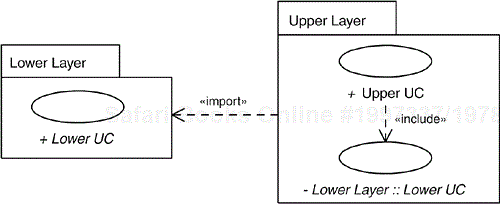
The Layered System: Reuse pattern contains two use cases and two packages with a package import relationship between the packages. The use case defined in the upper layer has an include relationship to the use case that is defined in the lower layer and imported into the upper layer. The use case defined in the lower layer is often, but not always, abstract (see Chapter 19, “Concrete Extension or Inclusion”).
This pattern is appropriate when the use-case instance starts in the upper layer, but will use a service defined in the lower layer. It is not suitable when the use-case instance starts in the lower layer.
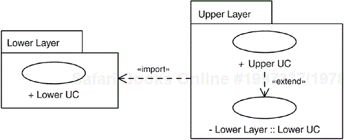
In another Layered System pattern, the use case defined in the upper layer extends the use case defined in the lower layer. Here the use-case instance starts in the lower layer, but services defined in the upper layer are inserted into it. The use case in the upper layer is normally abstract; that is, it will usually not be performed as an instance of its own.
The difference between this alternative and the previous one is the relationship between the upper use case and the lower use case.
This pattern is applicable when the use-case instance starts in the lower layer, but should not be used if it starts in the upper layer.
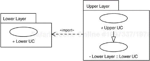
In the Layered System: Specialization pattern, the use case defined in the upper layer is a specialization of the use case defined in the lower layer; that is, the former has a generalization to the latter.
This pattern is applicable when the upper use case is of the same kind as the lower use case. (In UML, generalization is a taxonomic relationship; see Chapter 11, “Use-Case Generalization: Classification and Inheritance.”) It is not applicable whenever the use-case instance follows a combination of descriptions from the two layers.
In this alternative pattern, no lower-layer use cases are available. Instead, the access of the information inside the lower layer is described inside the descriptions of the use cases in the upper layer.
This pattern is used when the upper layer only performs single operations on information in the lower layer or when the lower layer consists of a platform that is not to be modified. The information in the lower layer is considered available in the system when writing use-case descriptions for the upper layer.
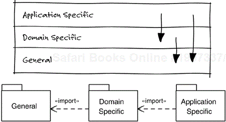
Most nontrivial systems are organized in layers, with lower layers containing basic parts and more application-specific parts placed higher up in the layer hierarchy (see Figure 22.1). The latter parts may (as a matter of course) make use of the parts located in the lower layers, although the opposite is not allowed; the general modeling principle when modeling a layered system is that an entity may only be dependent on elements in the same layer or on elements in lower layers, whereas it may not depend on elements higher up in the layer hierarchy. This principle leads to an overall structure having a general direction: from application-specific elements to elements that are more general. The number of circular or bidirectional dependencies is therefore reduced, because such dependencies are only allowed within layers, not between layers.
Figure 22.1. Systems are often organized in layers, in which elements in a lower layer may be used by elements in layers above, but not the other way around. It must be decided whether to allow access according to the arrow to the right in the upper part of the figure. In UML, layers can be modeled using packages with package import relationships in the allowed access direction.
When it comes to the question of whether it should be possible to access elements in layers further down in the layering structure—not immediately below the current layer—there are two schools of thought, one stating that this should be prevented, and the other allowing it. Whichever of the alternatives is chosen, it can be imposed by giving imported elements visibility according to the following principle: Giving elements imported into a certain layer from the layer below public (+) visibility makes them accessible by elements in the layer above, whereas if they are private (–) in the importing layer they are not visible above this layer. In the pattern models presented above, we have applied the conservative approach by making imported elements private, but this is obviously easily changed if the other approach is chosen.
We refer you to Software Architecture in Practice (Bass, Clements, and Kazman 2003) or Software Reuse: Architecture, Process, and Organization for Business Success (Jacobson, Griss, and Jonsson 1997) for a more thorough description of layers.
This layering technique is also applicable when using a framework or component library where the predefined parts and components are placed in a lower layer and the part of the application to be developed is put in the upper layer.
The structure of a system using layers also affects the use-case model. Although a specific usage of the system—a use-case instance—can span several layers (remember that a use-case instance is a complete usage of the system), the use cases themselves should not do so because the general modeling principles for layered systems say that an element should be located in one layer only. Different use cases will be placed in different, distinct layers based on what information and what services each layer is to contain. This technique implies that separate parts of concrete use cases will be extracted and put into separate, possibly abstract use cases defined in different layers. Relationships are defined between the use cases declared in the different layers to define the complete usages of the layered system. These relationships are of course defined in accordance with the general “downward” direction of the structure.
In the simple case when a usage of the system is localized to one layer—containing and exploiting only information and behavior situated in that layer—it is obviously modeled by a use case that is defined solely within that particular layer.
What then are the implications if the usage spans several layers—if a use-case instance uses information and performs behavior localized in multiple layers? To define one use case containing the complete declaration of such a use-case instance would be impossible, because such a use case would span over multiple layers. Instead, we must split such a use case into several use cases distributed over the layers—each use case to be defined in one layer only.
These use cases are bound to have different kinds of relationships to each other—include, extend, and generalization—so that the use-case instance can be assembled from all these declarations. Again, because of modeling principles, these relationships will always be directed downward in the layer hierarchy.
When use of a lower layer is limited to applying simple operations on information, defining use cases in the lower layer for this is often overkill. Such use cases would all be very simple and short, and would probably not contribute to the understanding of the lower layer. Instead, we simply consider the information the lower layer contains available in the system when writing use-case descriptions for the upper layer. This makes usage of the lower level embedded in the use-case descriptions instead of explicit in the model, according to the Layered System: Embedded pattern.
This pattern is also suitable in the special case where a lower layer consists of a platform over which we have no influence.
We say that a use case in the upper layer uses a service in the lower layer if there is an include relationship from the upper use case to the use case in the lower layer modeling the used service, as in the Layered System: Reuse pattern. In this way, we can reuse the more basic use cases defined in the lower layer when we define the use cases in the upper layer. A use-case instance will follow the flow declared in the upper use case, and in this declaration will be included the flow declared in the lower use case; hence, the use-case instance spans both the upper and the lower layer, as shown in Figure 22.2.
In a bank system, there are two layers. The lower layer contains parts for banking in general, such as handling accounts, managing stock portfolios, and handling loans. Use cases for these parts are defined within this layer. The upper layer contains parts that are specific for this particular bank system, such as financial advice for the customers based on their current situation (age, savings, loans, real estate, and so on). The use cases in this layer describe how they make use of use cases defined in the lower, more general layer.
For example, in the lower layer we will find a use case for buying and selling stocks. This use case includes another use case that retrieves and presents the customer's portfolio so that the
Clerkcan see the exact number of shares, bonds, liquid assets available, and so forth. In the upper layer, there is a use case to support theClerkin giving a customer financial advice. During this process, theClerkhas to be able to find out all about the customer's financial situation. Therefore, this use case must also include theView Portfoliouse case. An import relationship from the upper layer to the lower one makes it possible to define the include relationship within the upper layer.To sum up: The portfolio use case is defined in the lower layer, because it models a more general (or basic) service in the system. This makes it possible for other use cases to include it when modeling more specific (or advanced) services defined in the upper layer.
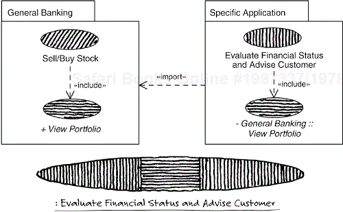
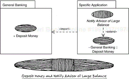
Figure 22.2. A use case in the upper layer may have an include relationship to a use case in the lower layer. A use-case instance will therefore span both the upper and the lower layer, as indicated by the hatching.
This pattern—Layered System: Reuse—proves useful when the flow starts in the upper layer and partly continues in the lower layer (possibly several times in different use cases).
If the flow instead starts in the lower layer (Layered System: Addition), we will use a lower-layer use case describing what happens if an actor of the system performs some action, such as sending some information to the system. This use case describes the system's response to this action, but only that part of the response that takes place in this layer. In the upper layer, we will find a use case that performs the application-specific part of the behavior.
In this case, the include relationship is not applicable to connect the two use cases, because the base use case is in a lower layer, implying that the direction of the include relationship would be upward. Instead, an extend relationship is defined from the upper to the lower use case. Hence, a use-case instance will start by performing the behavior declared in the use case that is defined in the lower layer, and then at the extension point continue by performing the behavior declared in the use case in the upper layer. Again, the use-case instance spans both layers even though each one of the two use cases is defined in only one layer. By using a relationship directed downward in the layering hierarchy, we follow the layer modeling principles (see Figure 22.3).
In our bank example, the customers can deposit money. If the sum of money in the account is large—that is, if the balance in the account passes a specific threshold value—an advisor of the bank is notified. The advisor will then contact the customer and suggest that they meet to discuss what should be done with this large sum of money. The customer can, of course, always decline that meeting, but the system should at least notify the adviser so that the contact can be made.
In the lower layer, there is a use case modeling how money is to be deposited. This use case is placed in the lower layer because it deals with a general service in the system. The notification use case is placed in the upper layer because it models a specific service for this system and has nothing to do with managing accounts. The use case is abstract because it will never be performed on its own; a notification will not be sent unless there is a use case modifying the balance of an account. To achieve the desired functionality, the notification use case extends the depositing use case; that is, a use-case instance performing the depositing may be extended with the actions described in the use case to notify the advisor.
These two patterns can be combined, of course. As shown in Figure 22.4, the flow can start as declared by a use case in the lower layer. This use case can be extended by multiple use cases in the upper layer. Once the flow is in the upper layer, it can include flows declared in use cases defined in the lower layer. A similar structure can be obtained if the flow starts in the upper layer.
In the example above, when the advisor is to be notified that the balance of an account exceeds a given threshold level, the system is also to register that this event has occurred so that the advisor can find information about it later. As we already know, this use-case instance starts in the lower layer when the depositing occurs. After the deposit, the balance is seen to exceed the threshold level, and therefore the use-case instance is extended with the actions of the notification use case in the upper layer. These actions include those defined in the use case that registers the event that, in turn, is defined in the lower layer (see Figure 22.4). Therefore, the use-case instance starts in the lower layer, continues in the upper layer, and then it is carried on in the lower layer again before it ends.
In some cases, especially where a framework is used, many predefined use cases are included in the system. These use cases exist in the layer modeling the framework. If some of these use cases are to be specialized to capture the exact behavior of the application at hand, the specializations of the use case are put in the application layer (the upper layer) and the generalizations will go from the upper to the lower use cases—once again, in accordance with the modeling principles for modeling layered systems. In this way, complete use cases can be reused, and developers need only provide the specialized parts of those use cases, according to the Layered System: Specialization pattern.
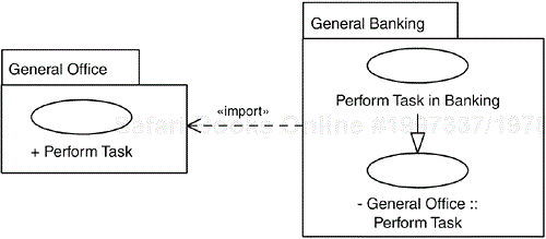
In many office systems, there is a part handling the registration and the performance of the work tasks. However, even though the registration service is often useful as it is, the functionality of the performance service must usually be specialized in each installation of the office system.
Assume that there is such an office system in our bank example. This system is included in a layer below
General Banking, calledGeneral Office, because it has nothing to do with banking per se. In this layer, there is a use case calledPerform Taskthat models that a task is selected from the collection of all the registered tasks, that the task is performed, that the task may have to be rescheduled if it could not be completed, and so on.However, in the bank system, all tasks having to do with something that affects a customer's money, loans, or securities must always be logged for security reasons. Therefore, the
Perform Taskuse case defined in the office system must be modified to capture this additional requirement. This modification is described in a use case, calledPerform Task in Banking, defined in theGeneral Bankinglayer, because this modification is specific to the banking business. Because the new use case is of the same kind as thePerform Taskuse case, a generalization is defined between the two, as shown in Figure 22.5.
This section presents the use-case description of the use cases in the bank example discussed in the previous section and shown in Figure 22.4. Therefore, it uses the first two Layered System patterns. The first use case is Deposit Money, which models how an amount of money is deposited into a bank account. Register Event is the second use case, modeling the registration of an event in a log, so that the information about the event can be retrieved later. The last use case, Notify Advisor of Large Balance, informs an advisor that the new balance of an account is above a specific threshold, so that the advisor can contact the customer and discuss what to do with the money. This use case, which is defined in the upper layer, both extends the Deposit Money use case and includes the Register Event use case. The latter two use cases are defined in the lower layer.
See also the Message Transfer: Automatic blueprint.
In principle, the modeling of a layered system will not introduce any specific techniques, as long as the dependency directions between the layers are fulfilled, which is to say that elements in a lower layer must not be dependent on elements in an upper layer. The existing techniques used for realizing use cases and their relationships are sufficient. Following are a few guidelines commonly used when modeling layered systems.
As mentioned previously, when the only part of a use case that belongs in a lower level is a simple operation on information in the lower layer, this can be modeled entirely within a use case in the upper level (Layered System: Embedded).
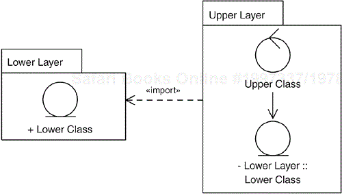
This implies that classes in the upper layer may have associations to entity classes in the lower layer, as long as these associations are used only for simple operations. These associations are defined in the upper layer, and should be navigable only in the direction toward the lower-layer class. This implies that the lower-layer classes must be imported into the upper layer to become available when defining the associations (see Figure 22.6).
When realizing an include relationship from a use case defined in the upper layer to an inclusion use case in the lower layer (Layered System: Reuse), we make use of a class defined in the lower layer and use it in the realization of the inclusion use case. This class, usually a control class (see Chapter 15, “Mapping Use Cases onto Classes”), is imported into the upper layer, and an association is defined in the upper layer from a class participating in the realization of the upper use case to this imported class (see Figure 22.7).
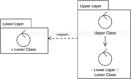
Figure 22.7. The realization of an include relationship from an upper-layer use case to a lower-layer use case is usually done with an association from a control class realizing the upper-layer use case to a control class realizing the lower-layer use case. The latter class must be imported into the upper layer to be available when defining the association.
This association is used for invoking the realization of the inclusion use case, and when the included flow is completed, the control is transferred back to the realization of the base use case using the same association.
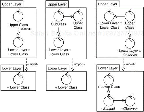
When realizing an extend relationship from a use case defined in the upper layer to a base use case in the lower layer (Layered System: Addition), we use a technique similar to the one described above; a class defined in the lower layer that is used in the realization of the base use case is imported into the upper layer. Because this class is not to be modified (it is defined in a lower layer and hence must be kept independent of the elements in the upper layer), however, we cannot define a communication from that class to a class defined in the upper layer to invoke the extension flow. Another technique must be used.
We can, for example, define an extend relationship from the class defined in the upper layer to the class defined in the lower layer (Jacobson et al. 1993). Another alternative is to define a subclass of the lower-layer class in the upper layer and let this class send a notification to relevant classes in the upper layer. A third option is to expand the second alternative and use the Observer design pattern (Gamma et al. 1995). However, this alternative requires that the classes in the lower layer have been prepared in advance for this pattern (see Figure 22.8), because we only have read access to the lower layer when developing the upper layer.
If a use case in the lower layer is specialized by a use case defined in the upper layer (Layered System: Specialization), two different techniques can be used depending on the situation. In the first case, the upper use case specializes a part of the flow defined in the lower use case. In this case, the class in the lower layer realizing the flow to be specialized is identified. This is usually a control class or a boundary class. This class is imported into the upper layer, and a new class with a generalization to the imported one is introduced in the upper layer. This new class realizes the specialized flow, possibly together with a collection of other classes, also defined in the upper layer (see Figure 22.9).
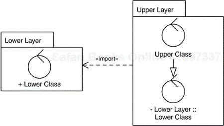
Figure 22.9. Realization of a generalization between use cases in different layers usually involves a specialization of a class defined in the lower layer.
In the second case, an additional flow is added by the upper use case. Here, the class performing the actions before the added ones is specialized in the upper layer. In the specialized version of the class, the new actions are added, possibly including communications to other classes defined in the upper layer (see Figure 22.9).
