Chapter 2. Storage
Storage will be one of the key components in your virtualized environment. In this chapter, we will look at the different types of storage and ways to successfully configure and use them within the ESXi environment.
2.1. Comparing ESXi Storage Options
Solution
Review the comparison tables in this recipe.
Discussion
Table 2-1 lays out the types of storage ESXi supports. Table 2-2 lists the features of different storage types that can be utilized in ESXi. It’s important to understand the technologies and their capabilities and limitations when setting up your ESXi environment.
You will achieve higher success and performance within your environment when using VMware with a SAN, regardless of which type of SAN you use.
Let’s take a look at each technology and the benefits of each.
- Fibre Channel
Fibre Channel has been around for years and gives you 2, 4, or 8Gbps of throughput from your ESXi servers to the SAN. People who are using Fibre Channel tend to have dedicated storage administrators and larger environments that require its robust feature set. Fibre Channel, however, can be more difficult to set up because of the switch zoning that needs to take place. However, zoning is a requirement if the SAN is directly connected to the servers.
- Local storage
Local storage implies exactly that. It’s a local disk or disks inside a server or JBOD that are either in a single or RAID configuration. This is the least beneficial type of storage to use in a virtualized environment because VMware requires a SAN to use some of the high-end features.
- iSCSI
iSCSI, which stands for SCSI over IP, has also been around for years. This technology is robust and allows flexibility, while giving good performance for the price. Many people are starting to gravitate toward iSCSI from Fibre Channel when it makes sense. It’s easier to configure and maintain and doesn’t require a dedicated SAN administrator. iSCSI can be set up on either 1GB or 10GB connections depending on the host bus adapter (HBA) and SAN vendors.
- Network attached storage (NAS)
NAS, often using the network file system (NFS), is also popular among the VMware community. Most of the SAN vendors today will provide some type of NFS- or CIFS-type connectivity. Performance can vary on NFS, but it’s still very usable in small- to medium-sized environments.
- Fibre Channel over Ethernet (FCoE)
Fibre Channel over Ethernet is a converged protocol that emulates Fibre Channel and is generally set up and configured in the same way as a normal Fibre Channel. The benefit to FCoE is you generally have a higher bandwidth connection, for example, 10GB or greater in which you isolate the Fibre Channel traffic from normal network traffic that flows over the link. This is beginning to become a popular option because it allows end users to eliminate cables inside their racks.
Selecting the Virtual Machine Datastore Location
Problem
You need best practice guidelines for placing your virtual machines on specific types of storage.
Solution
In this recipe, we have put together some industry standard best practices for placing virtual machines on certain types of storage.
Discussion
Before we begin, it’s important to mention that a lot of factors are involved when placing your virtual machines on storage. As the industry expands and new technologies come out, there is a standardization on storage tiering, which allows the SAN or storage array to automatically move data between different types of disks. For example, you might have a mix of 15,000 RPM and 7,200 RPM drives in a SAN. The goal of tiering is to place each type of data on a disk with a speed appropriate to the need and use for the data. The software on the SAN will automatically move work loads between the different types of disks, generally on the block level. It’s important to note that each SAN vendor does things slightly differently.
Here we will take a look at the different tiers and what might be placed inside those tiers from a virtual machine perspective.
As you can see, there is no real best answer for virtual machine placement. It’s a best effort based on your knowledge of the workloads in your environment. Because virtualization allows you to easily place virtual machines on different datastores, you can pick and choose until you find a suitable storage location. However, VMware has additional tools like vCenter Operations Manager that can help ensure specific metrics can be met inside your virtualized environment.
2.2. Storage Runtime Naming Scheme
Solution
This recipe breaks down the naming scheme so you can understand how it works.
Discussion
Figure 2-1 shows a typical list of volumes and their device names. In this figure we’ve listed multiple iSCSI volumes arranged them by the identification fields, followed by their device names, capacity, free space, and the type of filesystem on the volume.
The format of a storage device name in ESXi consists of three or four numbers separated by colons. As an example, in Figure 2-1, the device name for the first volume is vmhba38:C0:T0:L0. The numbers have the following meanings:
HBA:Adapter:Channel:Target:LUN
Our first volume’s datastore HBA has a device ID of 38. The second number, 0, is the storage channel number, the third number indicates that the target of the LUN is 0, and the LUN number is 0.
The third value—the target number—is incremented for each volume added to the HBA. It should be noted that if the same target is shared across multiple ESXI servers, this value can be different.
The first and third numbers may change for the following reasons (if they are changed, they will still reference the same physical device to which they were originally connected):
The first number belonging to the HBA can change if an outage occurs on the Fibre Channel or iSCSI network. In this case, ESXi will assign a different number to access the storage device. The first number can also change if the card is moved to another PCI slot in the server.
The third number will change if any modifications are made to the mappings on the Fibre Channel or iSCSI targets that are visible to the ESXI server.
2.3. Creating a Network for the Software iSCSI Initiator
Problem
You want to create a separate iSCSI network to isolate storage traffic for servers when communicating with the storage device.
Solution
Using vCenter, create a network and VMkernel port on which the iSCSI device can communicate. Because we are using software iSCSI, we will create one vSwitch assigned to vmnic1.
Discussion
Before ESXi can communicate with an iSCSI device, a VMkernel network port must be created within the network component of the vCenter server.
The VMkernel port can be configured on an existing network, but we strongly advise you to put your iSCSI traffic on its own network and port group, isolated from all other traffic. This ensures maximum performance for your virtual machines. Follow these steps:
Log in to vCenter Server and select the server from the inventory list.
Select the Configuration tab from the right window pane, navigate to Networking on the lefthand side, and click the Add Networking link in the upper right corner.
Under Connection Types, select VMkernel and click Next. The VMkernel option allows you to set up VMotion, iSCSI, or NAS in your ESXi environment.
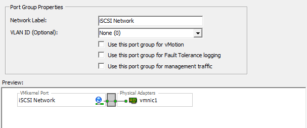
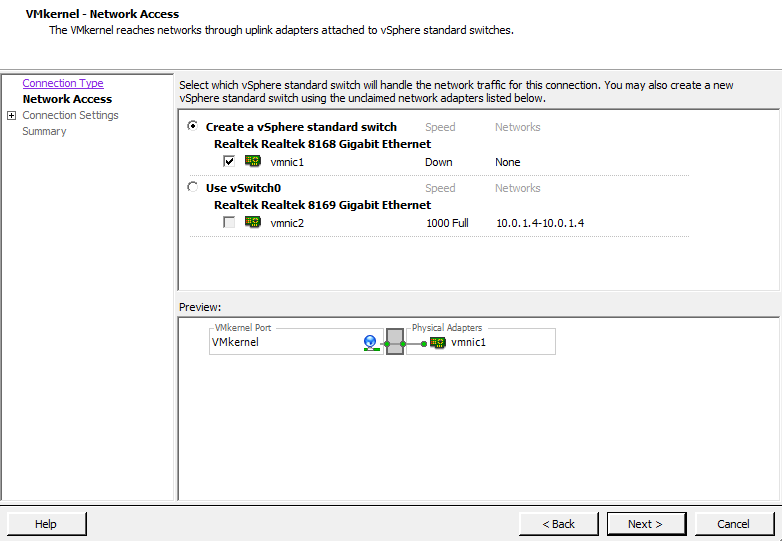
Under Network Access, select an unused network adapter (see Figure 2-2; we’ve selected vmnic1 for our VMkernel port) to set up your VMkernel on a separate network (recommended), or select an already existing vSwitch and Ethernet adapter to share iSCSI traffic with other traffic. Your options will be displayed in the lower portion of the screen, in the Preview section (Figure 2-2). Click Next.

You will be required to enter some information about the VMkernel port on the Connection Types screen (Figure 2-3).
First, configure the port group properties:
- Network label
The label by which the port group will be recognized within the virtual environment. It’s important to give this port group the same name on all physical ESXi Servers to ensure that VMotion and other aspects of the ESXi environment will work.
- VLAN ID (optional)
The network VLAN your port group will use to communicate. This should be specified only if you are using VLANs in your network infrastructure.
- Use this port group for VMotion
This option should not be selected when configuring a VMkernel for iSCSI or NAS traffic because this port group will not include VMotion traffic.
- Use this port group for Fault Tolerance logins
This option should not be selected when configuring a VMkernel for iSCSI or NAS traffic because this port group will not include VMotion traffic.
- Use this port group for management traffic
This option should not be selected when configuring a VMkernel for iSCSI or NAS traffic because this port group will not include VMotion traffic.
Configure the IP settings. Generally, you will want to use a static IP address here and not use the Obtain IP settings automatically; however, this may depend on your network configuration.
To configure additional options, such as DNS and advanced routing, click the Edit button.
Click Next to view the summary, and then Finish to create the port group.
2.4. Configuring Software iSCSI on ESXi
Problem
You want to use iSCSI connections to store area networks on an ESXi without an iSCSI host bus adapter.
Solution
Configure the software iSCSI initiator using vCenter.
Discussion
Because SCSI is an efficient, low-cost interface and many systems use the popular iSCSI protocol to reach network storage over a TCP/IP network, VMware ESXi allows iSCSI to connect ESXI servers to SANs. It is strongly recommended that you create a dedicated network for this traffic, as described in Recipe 2.3.
ESXi supports two different types of iSCSIs out of the box: hardware iSCSI and software iSCSI. Both are very powerful, but they’re set up differently and require different components to work. Each uses a different kind of software translation, called an initiator, to send traffic from the ESXI server to the network.
Hardware iSCSI uses third-party HBAs to transmit iSCSI traffic over the network. Typically, if you can afford the iSCSI HBA cards, you will benefit from faster data transfers. These cards also offer configuration options for fine tuning and can allow you to boot your ESXI server off the iSCSI SAN. Booting an ESXI server from the iSCSI SAN can be helpful in a situation where you have limited local disk space or are utilizing blade servers.
Software iSCSI uses built-in code in ESXi, specifically the VMkernel, to run the iSCSI protocol over standard Ethernet cards. This eliminates the cost of HBAs, but it puts a significant load on your ESXI server’s physical CPUs, which will affect system performance under high I/O loads. However, a lot of enterprise-grade systems will have TCP/IP offload engine-enabled Ethernet ports that can handle this offload and act like HBAs.
This section explains the basic configuration for a software iSCSI. By default, the iSCSI initiator is disabled, so you must enable it and indicate which SAN volumes you are communicating with:
Log in to vCenter Server and select the ESXi host you are configuring from the inventory list.
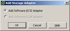
Select the Configuration tab from the right window pane. Click the Storage Adapters link on the lefthand side. Click Add and then select Add iSCSI Software Adapter (Figure 2-4). Click OK.
A confirmation dialog box will appear. Click OK (Figure 2-5).

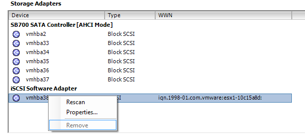
In the Storage Adapters configuration screen, right click the iSCSI Software Adapter (Figure 2-6) and choose Properties.
The iSCSI Initiator Properties window will appear (Figure 2-7). Enable software iSCSI by clicking the Configure button, putting a check in the Enabled box under Status, and clicking OK (Figure 2-7). A VMkernel port will be required for software-based iSCSI to work within the ESXI server; see Recipe 2.3 for more information.

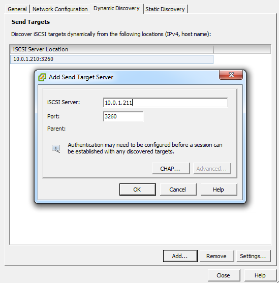
Click OK to return to the iSCSI Initiator Properties window. From here you can begin to configure the initiator to see the iSCSI SAN volumes. Click the Dynamic Discovery tab, and then the Add button. In the dialog box that appears, enter the IP address and port of your iSCSI storage array—the default is 3260 (Figure 2-8).
If your iSCSI SAN infrastructure requires use of the Challenge Handshake Authentication Protocol (CHAP), click the CHAP Authentication tab and enable and configure CHAP. Some iSCSI SANs, such as Dell’s EqualLogic PS series, will allow you to set three different authentication methods, including IP address matching, iSCSI initiator name matching, and CHAP authentication. It’s important to mention that CHAP authentication in ESXi 5.0 is one-way, allowing the array to identify the ESXI server.
Click OK to finish (Figure 2-8).
Next, to bind a physical NIC port to the VMkernel, select the Network Configuration tab and Click Add. Select the iSCSI networks that were created in Recipe 2.3 (Figure 2-9) and click OK.
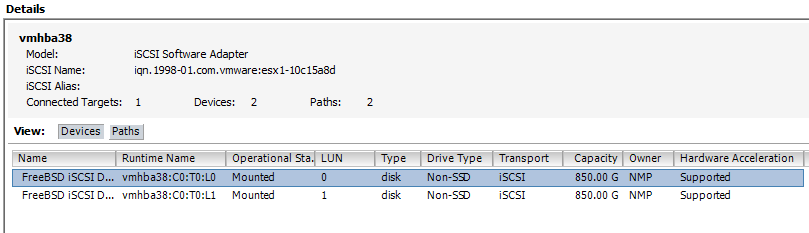
After clicking Close, you will be asked whether you wish to rescan for new disks. Click Accept, and ESXi will rescan. When the scan is complete, the new target will appear in the iSCSI software initiator’s Details window (Figure 2-10).


2.5. Configuring Hardware iSCSI with an HBA
Problem
You want to make iSCSI connections to storage area networks on ESXi with an iSCSI host bus adapter.
Solution
Use vCenter to configure the iSCSI HBA cards.
Discussion
Hardware-based iSCSI HBAs, such as a QLogic HBA, provides a dedicated and specially designed processor to send and receive iSCSI traffic. Before you purchase any iSCSI HBA cards, you should check the VMware HCL. It requires a hardware iSCSI initiator, which you can set up using the instructions in this section:
Log in to vCenter Server and select the server from the inventory list.
Select the Configuration tab from the right window pane and navigate to the Storage Adapters link on the left-hand side. Select the iSCSI HBA and click Properties. A new window will appear.
Unlike with the software iSCSI Initiator, a separate network inside ESXi is not required. You will generally create a separate physical network outside your ESXi environment and set the IP address and network information directly on the iSCSI HBA.
The iSCSI HBA we are using for our example is a QLogic QLE4062c, which has dual 1GB interfaces. If your iSCSI HBA has only one port, the model and device name (vmhba
N) will differ from those in our screenshot (Figure 2-11).

Click the Configure button to configure the IP address, subnet mask, default gateway, and optional iSCSI name and iSCSI alias (Figure 2-12). Once you’re finished, click OK to continue.

Click the Dynamic Discovery tab, then the Add button. Enter the IP address of the iSCSI server and, if necessary, change the default iSCSI port from 3260 to your customized value. Click OK, then click Close. The ESXI server will begin to scan for new devices.
New LUNs will appear in the Details window of the selected HBA card (Figure 2-13). The server can have a maximum of 64 LUNs, numbered SCSI Target 0, SCSI Target 1, and so on. In our example, the server has four targets, as identified in the Details window under vmhba4.
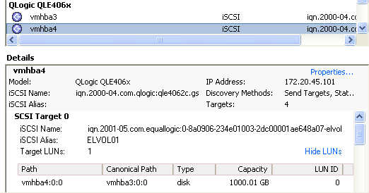
On the SCSI Target 0 LUN (Figure 2-13), notice that the path and the canonical path differ. This is because we are looking at the vmhba4 path view on the second port of the HBA, and the canonical path is set to route all traffic through the first port of the HBA, which is vmhba3.
See Also
2.6. Configuring iSCSI in Windows Virtual Machines
Problem
You want a Windows virtual machine to communicate directly with a SAN over your iSCSI connection.
Solution
Using the Microsoft iSCSI Initiator, you can configure your virtual machine to talk to your iSCSI SAN directly.
Discussion
Using Microsoft’s iSCSI Initiator, you can directly connect a volume that resides on a SAN directly to a virtual machine that is running Windows. This recipe assumes you have set up a separate network for the ESXI server and a virtual machine to use for iSCSI traffic, and that you have assigned a dedicated Ethernet port on the virtual server for ESXi traffic. This section explains how to download and install the initiator.
Allowing your virtual machine to directly connect via iSCSI to your SAN will allow you to use features from the SAN directly, for example, snapshots done on the SAN or other types of backups that require access to a specific LUN. Additionally, some software vendors might require the storage live outside a VMFS volume and this method can provide RDM-like capabilities.
If you are running Windows Vista or Windows 2008, the iSCSI Initiator is already included and no download is necessary. However, if you’re using Windows XP, 2000, or 2003, you’ll need to download the initiator from Microsoft’s website. Microsoft provides both 32-bit and 64-bit versions of the application.
Users who are required to download the application can install it by double-clicking the executable file and following the on-screen instructions. You will be presented with a new window giving you a set of options that include the following user-selectable options. However, we suggest leaving them checked by default.
- Virtual port driver
- Initiator service
This service handles the behind-the-scenes communication of iSCSI traffic.
- Software initiator
This will handle all the iSCSI traffic and works in conjunction with the initiator service to complete requests.
- Microsoft MPIO multipathing support for iSCSI
MPIO increases throughput by utilizing multiple interfaces. If you have a target that supports this, such as a Dell EqualLogic iSCSI SAN, you may wish to utilize this technology if performance becomes an issue for you. This option is not available on Windows XP.
Continue the installation of the initiator by accepting the license agreement. When the installation has completed, you will have a new icon on your desktop called Microsoft iSCSI Initiator. You’ll use this application to manage your iSCSI connections in Windows.
When you launch the application, you will be presented with a screen of options to configure the iSCSI connections. On the Discovery tab, click the Add button in the Target Portals section (Figure 2-14).

The Add Target Portal dialog box allows you to enter the IP address or DNS name of your iSCSI SAN or array. The default port is 3260; you should change this if you’re using a different port on the array. If you need to configure CHAP authentication or will be using IPsec for communication between the initiator and the iSCSI array, click the Advanced button and configure the necessary options.
Once you are satisfied, click the OK button to make the connection to the iSCSI array. The IP address or DNS name of the target will show up in the Target Portals area of the Discovery tab.
After creating the initial connection to the iSCSI array, you need to specify which volume you will connect to and mount on the Windows machine. Click the Targets tab to see the list of targets that are available for you to use (Figure 2-15).

Select the volume to which you will be connecting and click the Log On button. A new window will pop up with the target name and two options (Figure 2-16). The options are:
- Automatically restore this connection when the system boots
Selecting this option will make the system automatically reconnect to the volume each time Windows reboots. Unless you have a very good reason not to, you should always check this box. If this option is not selected, the volume will need to be manually reconnected each time the system boots.
- Enable multipath
This option should be checked only if you plan on using multipathing for better reliability and performance. It requires multiple Ethernet cards dedicated to the iSCSI task.
It can be valuable if you have the necessary hardware, need high availability, and previously configured multipathing when installing the initiator.
Once you are satisfied, click the OK button. The status for the target under the Targets tab will switch to Connected, showing that the volume is connected.

Now that the Windows machine can see the volume, you need to make, configure, and format the volume in Windows. Windows will treat the new iSCSI volume the same as if you had added a physical hard drive to the server.
Right-click on My Computer and select Manage. Choose the Disk Management option. Because the volume is presumably a new volume with no data, Windows will pop up a new window with the Disk Initialization wizard.
Follow the steps presented by this wizard and select from either a basic disk (recommended) or a dynamic disk (this is not recommended for Windows iSCSI). Once the disk has been initialized, you will need to create a partition and format the new volume by right-clicking on the new disk in the Disk Management window.
2.7. Opening Firewall Ports for an ESXi iSCSI Software Initiator
Problem
Your firewall is blocking your ESXI server from communicating with storage over its iSCSI connection.
Solution
Use vCenter to open the necessary firewall port.
Discussion
In order for the iSCSI software initiator to communicate with its targets, port 3260 needs to be opened for outbound traffic on the ESXi Server’s firewall. In ESXi 5.0, this port will be opened for you automatically when software iSCSI is enabled. However, for troubleshooting, or if there becomes a need to disable and reenable this service, follow the directions that follow.
Using vCenter, this task is easy. For each ESXI server that is part of your cluster or will be using the iSCSI Software Initiator, follow these steps:
Log in to vCenter Server and select the ESXi hosts from the inventory list.
Select the Configuration tab from the right window pane. Navigate to the Security Profile link on the left-hand side, and click the Properties link in the lower right corner under the Firewall section to display the Firewall Properties window. Look for the Software iSCSI Client service and select the box next to it to open the firewall on the ESXI server (Figure 2-17). Click OK when you’re done.

See Also
2.8. Multipathing with iSCSI
Problem
You want to route iSCSI traffic from an ESXI server over multiple paths for speed or redundancy.
Solution
Use vCenter to view and change multipath settings.
Discussion
One of the nice things about iSCSI is that it is IP based, so it already has built-in support for multipathing using IP routing if you are using dynamic routing protocols on your network. This configuration of iSCSI represents a simpler alternative to Fibre Channel.
The steps for configuring multipathing are as follows:
Log in to vCenter Server and select the server from the inventory list.
Select the Configuration tab from the right window pane and navigate to Storage. Then select the datastore you wish to modify and click Properties under the Datastore Details section of the screen.
In the properties window, click the Manage Paths button (Figure 2-18).
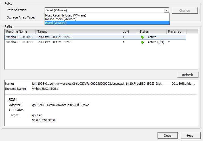
Path selection and paths will be displayed (Figure 2-19). The path selection will be Fixed, most recently used (MRU), or round robin. You may see third-party options as well if you have installed custom multipathing drivers from your SAN manufacturer. If you are using a SAN, it’s highly suggested to use their multipathing drivers, if available.
The ESXI server will automatically decide the default path depending on the make and model of your SAN. If the array is not an ESXi supported device, the default path will be set to active/active and the other options may not be available for you to use. Please refer to the hardware compatibility list found at http://www.vmware.com/go/hcl to ensure your hardware is fully supported.
Failover is handled using one of the following policies:
- MRU
Uses the last access path for your storage traffic. For example, if you were using path 1 and it failed over to path 2, the device will continue to use path 2 even after path 1 comes back online.
- Fixed
Tries to use a specific path. For example, if you set your path policy to Fixed on path 1 and it has a failure, the device switches to path 2 until path 1 is restored, then switches all traffic back to path 1. This is the default policy for active/active storage devices such as Dell EqualLogic iSCSI SANs.
- Round robin
This method uses an automatic path selection algorithm that will rotate through all active paths when connecting to active/passive arrays, or if you are using an active/active SAN, it will use all the available paths.

Click the Manage Paths button to configure the path settings (Figure 2-19).
From the Path Selection drop-down menu you will be able to select the available pathing options available to you. Select the multipathing option you desire and click the Change button. Then click the Close button to save the configuration.
2.9. Adding Fibre Channel Storage in ESXi
Solution
Use vCenter to configure the new storage and present the LUN to the ESXI servers.
Discussion
Before you can configure the Fibre Channel disks on the ESXI server, you must first create the LUN on the disk array (SAN) and set up the specific Fibre Channel zoning permissions. Normally, this is done in a utility that is provided by the SAN manufacturer. Fibre Channel zoning will take place on your Fibre Channel fabric on your switching environment. That is outside the scope of this recipe, so please refer to the documentation from your SAN and Fibre Channel switch manufacturers.
VMware has some best practice guidelines in place when using Fibre Channel storage. We’ll outline the VMware best practices in the following before we look at adding new VMFS datastores via the Fibre Channel fabric.
- House only one VMFS datastore per LUN
An example to avoid would be creating a 1TB LUN and creating two 500GB datastores on that volume. Instead, create a 1TB datastore on the 1TB LUN.
- Multipathing is generally set to support your SAN
VMware has specific multipathing policies depending on the SAN vendor and the type of SAN you are using, for example, active/active, active/passive, etc. It’s best practice to not modify the datastore pathing unless you understand the implications. However, some SAN vendors provide their own plug-ins that utilize the vSphere API and are acceptable to use.
- Document everything
As your environment grows, it’s really important that you document every detail. This will help troubleshoot later and, additionally, it will help keep your VMware environment cleaner.
When the SAN-side configuration is completed, you can use vCenter to add the new disk to your ESXI servers:
Log in to vCenter Server and select a ESXi host from the inventory list.
Select the Configuration tab from the right window pane and navigate to Storage. Click the Add Storage link.
Select the Disk/LUN storage type and click Next to proceed.
Select the Fibre Channel device that will be used for your VMFS datastore. Click Next to continue. If the disk you are formatting is blank, the entire disk space is presented for configuration.
If the disk is not blank, review the current disk layout in the top panel and select the appropriate configuration method from the bottom panel (this will erase and remove all data from the disk):
- Use the entire device
Selecting this option will dedicate all the available space to the VMFS datastore. This is the suggested option for VMware access, and selecting this option will remove all data currently on the LUN.
- Use free space
Selecting this option will use the remaining free space to create the VMFS datastore.
When you are satisfied with your decision, click Next to continue.
In the Disk/LUN properties page, enter the name by which you want to refer to this datastore. Click Next to continue.
If you need to adjust the block sizes, do so and click Next to continue.
Review the summary and click Finish to add the new datastore.
Note
You do not need to add the same datastore to multiple ESXI servers. After it has been added to one, the others will see it if the correct zoning has been configured or if no zoning is present on your fibre switch.
2.10. Creating a Raw Device Mapping for Virtual Machines
Problem
You want direct access, without going through the virtual filesystem, from a virtual machine to a disk on your storage network.
Discussion
RDM allows virtual machines to have direct access to a LUN on a physical storage system without the use of a VMFS datastore.
VMware generally suggests that you store your virtual machine files on a VMFS partition. However, certain situations may require the use of RDM, such as MSCS clustering that spans over physical hosts, or the use of SAN technologies inside your virtual machine. RDM is supported only over Fibre Channel and iSCSI at this time.
RDM has two different modes:
- Virtual compatibility mode
This mode allows the RDM to act like a VMDK (virtual disk file) and allows the use of virtual machine snapshots within ESXi. Virtual compatibility mode is also compatible when initiating a vMotion.
- Physical compatibility mode
This mode allows direct access to the device, but gives you less control within ESXi. For example, you will not be able to snapshot the data using ESXi. However, if your SAN supports snapshot technology, you will be able to use it on this volume.
To add an RDM disk to a virtual machine that has already been created:
Log in to vCenter Server and select the virtual machine to which you wish to add the RDM.
From the Summary tab on the virtual machine, click Edit Settings.
When the new window appears, click the Add button.
The Add Hardware wizard will open. Select Hard Disk, then click Next.
You will be presented with a list of options. Select Raw Device Mapping and click Next.
Select the LUN you wish to use for your RDM (Figure 2-20) and click Next.

From the available list of disks, select the LUN you wish to use for your virtual machine.
Select the datastore for your RDM mapping file. You can store the mapping file on the same datastore as the virtual machine files (described in Recipe 2.16), or on another datastore. If you have N-Port ID Virtualization (NPIV) enabled, ensure that the RDM mapping files are on the same datastore as the virtual machine files. Once selected, click Next to continue.
You will be presented with a choice of two compatibility modes, detailed earlier in this recipe. Make your selection and click Next to continue.
Select the virtual device node and click Next to continue.
If you selected virtual compatibility mode, you will need to choose between the two following modes:
Once you have made your selection, click Next to continue and click Finish to add the RDM to the virtual machine.
2.11. Creating a VMkernel Port for Access to NFS Datastores
Solution
Create a VMkernel port to allow ESXi to communicate with NFS.
Discussion
Although a lot of larger ESXi environments use Fibre Channel or iSCSI, ESXi also supports the use of NFS. As with software-based iSCSIs, you will need to create a VMkernel on the ESXI server for NFS traffic to pass over. It is recommended that you configure the VMkernel to use a dedicated network, but you can configure it on an existing network if necessary. Here are the steps:
Log in to vCenter Server and select the ESXi host from the inventory list.
Select the Configuration tab from the right window pane and navigate to Networking on the left-hand side. Click Add Networking in the upper right corner.
Under Connection Types, select VMkernel and click Next.
If you are going to set up your VMkernel on a separate network (recommended), you will want to select an unused network adapter; alternatively, select an already existing vSwitch and Ethernet adapter. The options will appear in the lower portion of the screen, in the Preview section (Figure 2-21). After making your selection, click Next.
You will be required to enter some information about the VMkernel port on the Connection Settings screen (Figure 2-22). Click Next once the Network Label is set.
First, set the port group properties:
- Network label
The label by which the port group will be recognized within the virtual environment. It’s important to give the port group the same name on all physical ESXi Servers.
- VLAN ID (optional)
The network VLAN your port group will use to communicate. Specify this if you are using VLANs in your network infrastructure.
- Use this port group for VMotion
Because the VMkernel also handles VMotion traffic, this option is available when configuring the NFS VMkernel. However, you should leave it unchecked because it is not recommended to run VMotion traffic over the same network as your storage traffic.
Next, configure the IP settings as shown in Figure 2-23:
Further options, such as DNS and advanced routing, can be configured by clicking the Edit button.

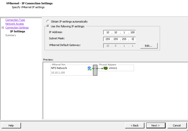
Click Next to view the summary, and then click Finish to create the port group.
Before ESXi can communicate with the NFS datastore, you have to configure it to use the storage, as described in the next section.
2.12. Configuring ESXi to Use NFS
Solution
Use vCenter to configure the ESXI server so it recognizes the NFS device.
Discussion
NFS is becoming a popular storage tier because it is cost-effective and provides reliable speed. VMware supports HA, DRS, vMotion, and virtual machine snapshots on NFS datastores.
Before you follow this recipe, set up a VMkernel port to communicate with the NFS datastore, as described in Recipe 2.11. Then configure the ESXI server as follows:
Log in to vCenter Server and select the server from the inventory list.
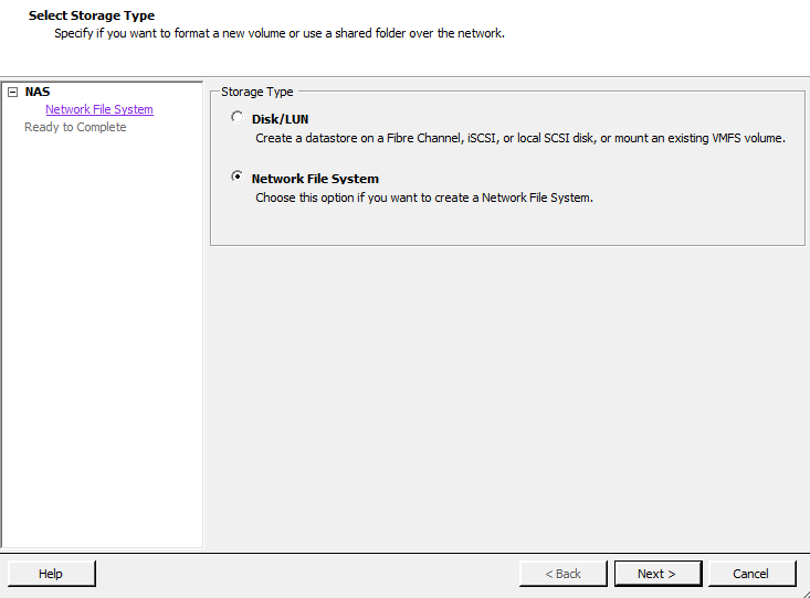
Select the Configuration tab from the right window pane, navigate to the Storage link on the left-hand side, and click Add Storage in the upper right corner.
A new window will appear with two options: Disk/LUN or Network File System (Figure 2-24). Select Network File System and click Next to continue.
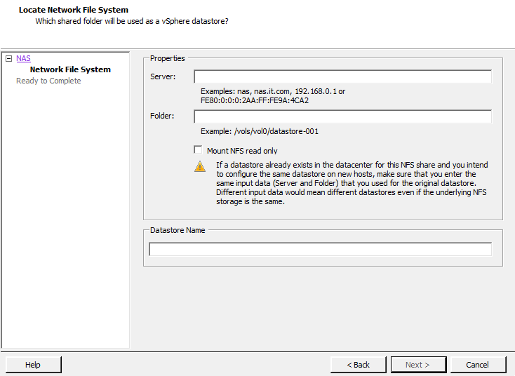
You will now be asked to enter some information about the NFS share (Figure 2-25). When finished, click Next.
- Server
The name or IP address of the device that is serving the NFS share
- Folder
The directory on the NFS device you are going to mount
- Mount NFS read only
This allows the NFS datastore to be read only.
- Datastore name
The name you wish to give the new datastore (for example, NFS01)
2.13. Creating a VMFS Volume in vCenter
Solution
Using vCenter, you can easily create and attach new VMFS volumes.
Discussion
Adding an additional VMFS volume to your ESXI servers is pretty straightforward for all aspects of storage. For example, once configured on the SAN side, Fibre Channel and iSCSI disks will be visible to your ESXI server, and local disks will be detected automatically.
When adding a new disk to your ESXI servers in a clustered environment, where multiple ESXI servers will be accessing the SAN LUN/datastore, you only need to add it to one ESXI server. After the datastore is created, you can rescan or refresh the existing servers and the datastore will appear.
ESXi 5 allows you to have 256 VMFS datastores per host, with a maximum size of 64TB. The minimum size for a VMFS datastore is 1.3GB; however, VMware recommends a minimum size of 2GB.
Warning
If you try to add the same datastore to each individual ESXi Server, you will get data corruption and configuration problems.
Follow these steps to create the VMFS volume:
Log in to vCenter Server and select the ESXi host from the inventory list.
Select the Configuration tab from the right window pane, navigate to Storage, and click the Add Storage link.
Select the Disk/LUN storage type and click Next to proceed.
Select the device to use for your VMFS datastore (Figure 2-26). The device may be a local, iSCSI, or Fibre Channel disk. Click Next to continue. If the disk you are formatting is blank, the entire disk space is presented for configuration.
If the disk is not blank, review the current disk layout in the top panel and select the appropriate configuration method from the bottom panel:
- Use the entire device
Selecting this option will dedicate all the available space to the VMFS datastore. This is the suggested option for VMware servers, and selecting this option will remove all data currently on the LUN.
- Use free space
Selecting this option will use the remaining free space to create the VMFS datastore.
After making your choice, click Next to continue.
Select the File System Version that you wish to use (Figure 2-27). In ESXi 5, you have the option to create VMFS-5 and VMFS-3 file systems. VMFS-3 limits the size of each datastore to 2TB, whereas VMFS-5 allows you to create datastores that can scale up to 64TB. Generally, you will select VMFS-5, unless you have a mixed environment of older ESX versions that share the datastore. Click Next to continue.
Review the disk layout (Figure 2-28). If you are satisfied, click Next to proceed.
On the Properties page, enter the name you want to give this datastore (Figure 2-29). Click Next to continue.
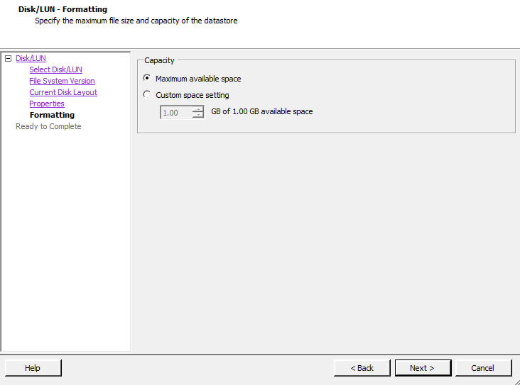
On the Capacity/Formatting screen, select either Maximum available space or choose a Custom amount of space to allocate to the datastore (Figure 2-30). Generally, you will want to use the maximum amount of space. Unlike with ESX 3 and 4, version 5 will standardize on a 1MB block size for the datastore when using VMFS-5. However, if you selected VMFS-3, you will need to choose a block size as well. The block size will determine the amount of individual files you can store on the datastore.
Click Next to continue once you have selected the capacity option that fits your needs.
Review the summary and click Finish to add the new datastore.
After the datastore has been created, you may need to click Refresh to see the new datastore. If multiple ESXI servers connect to the same datastore, you will need to refresh the storage on each one to see the new datastore.


See Also
2.14. Performing a Storage Rescan
Solution
Use the rescan feature in vCenter Server.
Discussion
There may be times when it is necessary to rescan your ESXi Server’s storage devices. These situations include:
When changes are made to the disks or LUNS available to the ESXI server
When changes are made to the storage adapters in the ESXi Server
When a new datastore is created or removed
When an existing datastore is reconfigured, for example, by adding an extent to increase storage
To rescan a server’s storage adapters:
Log in to vCenter Server and select the ESXi host from the inventory list.
Select the Configuration tab from the right window pane, navigate to Storage Adapters on the left-hand side, and click Rescan.
Alternatively, to rescan a specific adapter, you can right-click on that adapter and select Rescan.
If you wish to rescan for new disks or LUNs, select Rescan in the upper right corner and then choose the Scan for New Storage Devices option. If new LUNs are discovered, they will appear in the disk/LUN view.
To discover new datastores or update existing datastores after a configuration change, select the Scan for New VMFS Volumes option. If a new datastore is found, it will be displayed in the datastore view.
2.15. Creating a VMFS Volume via the Command Line
Problem
You must create a new VMFS volume but you do not have access to vCenter Server, or you want to create an automation script.
Discussion
The vmkfstools command
creates a new VMFS volume. It also assigns it a unique UUID, which is a
hexadecimal value that incorporates the SCSI ID and label name into the
volume’s metadata. Run this command on the ESXi host’s service
console:
vmkfstools --createfs vmfs5 --blocksize 1m disk_ID:PThe --createfs option tells
the command which type of VMFS volume to create. In our case, we created
a VMFS-5 volume. The -S option allows you to
specify a label for your volume, which should be a simple name.
See Also
2.16. Viewing the Files that Define a VMFS Volume
Problem
You need to find information about a VMFS volume, but this information is contained in files on that volume rather than in the vCenter.
Solution
Each virtual machine has a directory with files that define and control the virtual machine. You can view the contents of this directory and read the files themselves, because they’re text based.
Discussion
Many files make up a virtual machine. Understanding the purpose of each one helps you keep your virtual machine environment running at top performance:
- .vmx
- .vmss
- .vmdk
Holds the operating system and data for the virtual machine. This file is based on the .vmx file.
- .vmem
- .vmsd
The dictionary file for snapshots and associated disks. If you have snapshots or multiple disks, this file keeps track of them.
- .nvram
- .vmx.lck
A lock file is created when the virtual machine is powered on.
- -flat.vmdk
- f001.vmdk.filepart
The first extent of a preallocated disk that has been split into 2GB files.
- s001.vmdk
The first extent of a growable disk that has been split into 2GB files.
- -delta.vmdk
Holds the differences between the actual virtual machine and snapshot differences. This allows you to roll back your virtual machine to a previous state or merge the current state with the old state.
- -Snapshot#.vmsn
These files are located within the virtual machine’s directory on
the storage volume, which is typically /vmfs/volumes/DATASTORE/VIRTUALMACHINE.
For example, our server, which is named
W2KStandardBase, is on the
ELISCSI01 database store, and its path is /vmfs/volumes/ELISCSI01/W2K3StandardBase.
2.17. Increasing the VMFS Volume Capacity
Solution
Using the vCenter server, you can add an extent to your existing datastore to add more space.
Discussion
An extent is a physical hard drive partition on a physical storage device, such as a Fibre Channel, iSCSI SAN, or local disk. These partitions can be dynamically added to an existing VMFS-based datastore, allowing you to grow as needed. Datastores can span multiple extents and will be presented to ESXi as a single volume.
Adding new extents can be done while the existing VMFS datastore is online. This makes adding new space really easy. Each datastore can span up to 32 extents.
It should be noted that the first VMFS datastore (disk) in the extent holds the metadata for the entire datastore, including all new extents. If the first extent is corrupted or damaged, you are at risk of losing all the data on the entire extent set.
Add an extent as follows:
Log in to vCenter Server and select the ESXi host from the inventory list.
Select the Configuration tab from the right-hand window pane, navigate to Storage on the left-hand side, and select the datastore to which you wish to add the extent.
Once the datastore is highlighted, right click and select the Properties link (Figure 2-31).
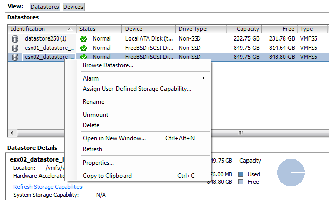
A new window will appear with information regarding the datastore. Click the Increase button, which appears under the General section (Figure 2-32). A new window will pop up.
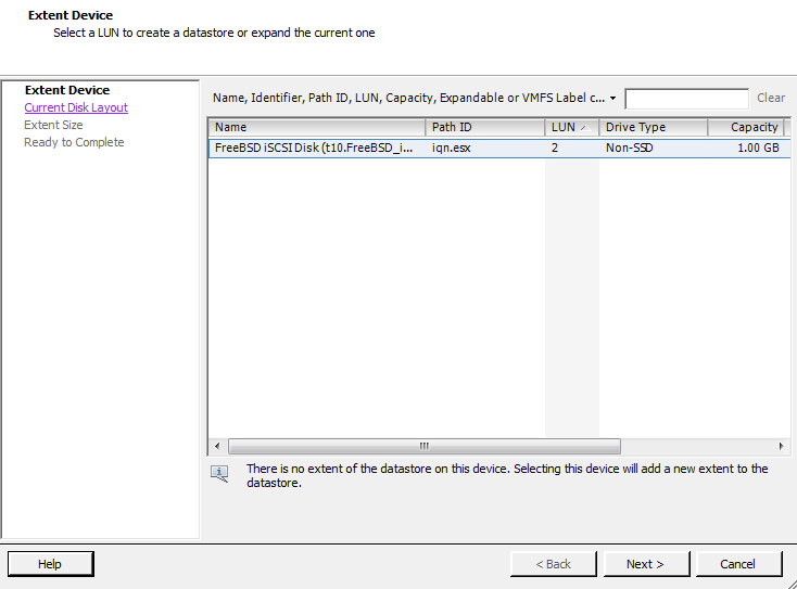
Select the device from the list of available storage devices (Figure 2-33) and click Next.
Review the disk layout. When you are satisfied, click Next.
Select how the space should be used on the extent. You will have one or many of the following options from which to choose. Set the capacity for the extent. If using the custom setting, the minimum size is 1.3GB. When you are done setting the size, click Next.
- Maximum available space
Allows all the available space on the device to be used in the extent.
- Custom setting
Allows a custom amount of space to be used on the extent.
Finally, once you are satisfied, click Finish and the process to increase the datastore will begin.

Once the datastore has been expanded, you can click on the datastore to view the new extent in the lower Details window. You will also need to refresh the datastore on each host so the new capacity will be reported correctly.
Note
You cannot remove individual extents after they have been added to a datastore; you can only remove the entire VMFS datastore, which will result in losing all of its data.
2.18. Reading VMFS Metadata
Discussion
The metadata in a VMFS volume is made up of six parts:
Block size
Number of extents
Volume capacity
VMFS version
Label
VMFS UUID
The vmkfstools command lets
you view the metadata in a specific VMFS volume:
vmkfstools -P -h pathnameThe -P option allows you to
read the metadata, and the -h option tells the
vmkfstools command to
display amounts in megabytes, kilobytes, or gigabytes, instead of the
default bytes. The
pathname is the pathname of your VMFS
filesystem. For example:
VMFS-5.54 file system spanning 1 partitions.
File system label (if any): esx02_datastore_lun1
Mode: public
Capacity 849.8 GB, 848.8 GB available, file block size 1 MB
UUID: 4f546274-32257e8a-132c-5404a64c91b1
Partitions spanned (on "lvm"):
	t10.FreeBSD_iSCSI_Disk______001d60f814da001_________________:1
Is Native Snapshot Capable: NO
2.19. Creating a Diagnostic Partition
Solution
Use the vCenter to create a diagnostic partition.
Discussion
ESXI servers need to have a diagnostic or dump partition in order to run. These partitions store core dumps for debugging and are used by the VMware technical support team. Diagnostic partitions can be created on a local disk, on a shared LUN on a Fibre Channel device, or on a device accessed by a hardware-based iSCSI initiator connection. Diagnostic partitions are not supported on software-based iSCSI initiators.
The diagnostic partition must be at least 100MB in size. If you use a shared storage device, each ESXI server must have its own separate diagnostic partition.
If you choose the Recommended Partitioning scheme when installing your ESXI server, the installer automatically creates the diagnostic partition for you. The following steps create a diagnostic partition if your ESXi installation lacks it:
Log in to the vCenter server and select the ESXi host from the inventory list.
Select the Configuration tab from the right window pane, navigate to Storage, and click Add Storage.
A new window will appear allowing you to select the storage type. Select the Diagnostic option and click Next to continue. If you do not see the Diagnostic option, your ESXI server already has a diagnostic partition. If your ESXI server already has a diagnostic partition, you can access it by issuing the
esxcli system
          coredump
command at the command line.Select the type of diagnostic partition you wish to create. You have three options:
After making your selection, click Next.
Select the device on which to create the partition and click Next.
Finally, review the partition configuration and then click Finish to create the diagnostic partition.
2.20. Removing Storage Volumes from ESXi
Solution
Use the vCenter to remove a volume from ESXi.
Discussion
The steps to remove a volume follow:
Log in to the vCenter server and select the ESXi host from the inventory list.
Select the Configuration tab from the right window pane and navigate to Storage. Right-click on the datastore you wish to remove, and choose Remove.
A pop-up window will appear asking you to confirm the removal of the datastore. It’s very important to make sure you know which datastore you want to remove, because this window provides no details on the datastores.
Click Yes if you are positive the correct datastore has been selected, and the datastore will be removed. All of the data will be deleted.
2.21. Determining whether a VMFS Datastore Is on a Local or SAN Disk
Problem
Using the vCenter, find if a specific VMFS datastore is on a local disk or connected to a SAN or NFS device.
Solution
Through vCenter, you can determine the physical location of a VMFS datastore.
Discussion
To find out where your VMFS datastore is located:
Log in to the vCenter server and select the ESXi host from the inventory list.
Select the Configuration tab from the right window pane and navigate to Storage.
Find the datastore you want to check. Look for the Device column (Figure 2-34). This will identify if the datastore is Local or if it’s connected to a Fibre Channel or iSCSI SAN. In the example, we can see that datastore250 is a local disk datastore specific to the ESXi host.

2.22. Adjusting Timeouts When Adding Storage in vCenter
Solution
Adjust the timeout value in the vCenter.
Discussion
timeouts can occur for various reasons when adding new storage via the vCenter. It may be simply that the timeout values are just too short, but be aware that lengthening these values is not a fix-all solution; there may be a larger underlying problem in networking or I/O that you should investigate.
To lengthen the timeout in the vCenter client, navigate to Edit→Client Settings→Remote Command timeout→Use a custom value. The value is shown in seconds. Adjust it to a higher number (perhaps two times what is already set).
2.23. Setting Disk Timeouts in Windows
Problem
A Windows guest operating system will sometimes timeout when a SAN is rebooted or goes through a failure and recovery.
Solution
You can adjust the disk timeout value in the Windows registry.
Discussion
Default timeouts on Windows servers may be too short for a SAN recovery. During the time your SAN is down and Windows is trying to write data, it is possible for data to be lost or corrupted if your timeout values are not high enough. You can change the timeouts on both Windows Server 2000 and 2003 by editing the system registry:
Once these changes have been made, Windows will wait 60 seconds before generating disk errors. If 60 seconds isn’t long enough, you can adjust the value to suit your specific needs.
Renaming Datastores
Solution
You can use vCenter to rename your datastores. Follow these simple steps.
Discussion
Log in to your vCenter server and select the ESXi host that has the datastore you wish to rename.
Click the Configuration Tab and then select Storage.
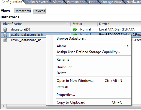
Finally, select the datastore and right-click and choose Rename (Figure 2-35).
Once the datastore is renamed, any ESXi host that has access to that datastore will see the new name, and it will be updated across all ESXi hosts.