Chapter 3. Networking
Networking is a crucial aspect of the ESXi virtual environment. It’s important to understand the technology, including the different pieces that make it up and how they work together. In this chapter, we will look at different networking elements inside the ESXi platform and how to configure and build those different pieces.
3.1. Configuring ESXi Network Ports and the Firewall
Problem
You need to identify the ports used by ESXi services and ensure they are open for traffic to pass.
Solution
Review and discuss the ports and their functions within the environment.
Discussion
Connections to the ESXi host through the vCenter server, Secure Shell, or the Web must use specific ports. ESXi handles most communication through the following ports; they cannot currently be changed, so make sure they are open on your firewall if you have internal firewalls inside your network.
- Port 902
The vCenter server uses this port to send data to the ESXI servers it manages. The listening process (vmware-authd) on the ESXI server handles the flow of traffic.
- Port 903
Both the vCenter client and the web client use this port to provide mouse keyboard screen (MKS) service from the virtual machine to the end user over Transmission Control Protocol/Internet Protocol. This port also handles all interactions with the virtual machine when it is accessed via the console in the vCenter client or via the Web.
- Port 443
vCenter clients, web clients, and the Software Development Kit all use this port to send data to an ESXI server managed by the vCenter server. This port is also used if you connect to the ESXI server directly, bypassing the vCenter server. The clients will connect to the ESXI server via the Tomcat or SDK instance, and the running process on the ESXI server (vmware-hostd) will handle the traffic.
Note
For a complete reference of all ports inside the vSphere product suite see: http://kb.vmware.com/selfservice/microsites/search.do?language=en_US&cmd=displayKC&externalId=1012382
When communications regarding VMware HA, migrations, cloning, or VMotion take place between multiple ESXI servers, it’s important to have the following firewall ports open to ensure all the traffic gets from the source to the destination without any problems:
By default, to ensure you don’t unintentionally leave open services that could be a security risk, ESXi is installed with no firewall ports open. You have to configure it to open the ports just mentioned, along with any that are needed for the actual services you run on your guests, such as web services, DNS, etc.
In Chapter 6, we will discuss
how to manage the ESXi Firewall via the command line and how to
enumerate the ports that are available using the esxcli network firewall command. Here, we’ll
take a look at some of the firewall features, using the vCenter client.
It provides some useful additional features—notably, the ability to tie
the starting and stopping of services to the opening and closing of
ports. Any changes made via the command line will not take advantage of
these settings.
Configure the firewall and services as follows:
Log in to the vCenter server and select the ESXi host from the inventory list.
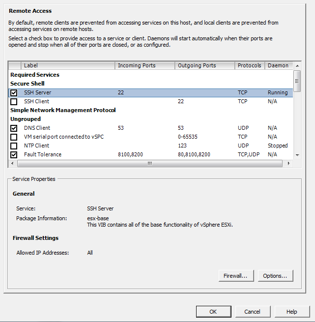
Select the Configuration tab from the right window pane and navigate to Security Profile. A list of services and ports will appear in the right-hand window (Figure 3-1).

Click the Properties link under the Firewall Options to open the Firewall Properties window. From here, you can open the port on the firewall by checking the box next to the service (Figure 3-2).
You can enable automatic starting and stopping by selecting a service and clicking the Properties link under the Services section. This new window will be displayed for certain services that support options such as SSH or NTP. Figure 3-3, for instance, shows the options available for SSH. Not all services offer these three options.
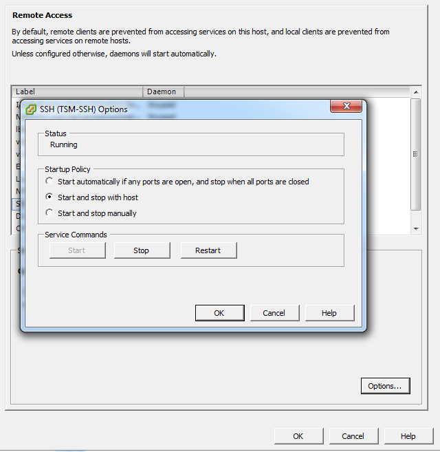
The configurable options for SSH running under ESXi are:
- Start automatically if any ports are open, and stop when all ports are closed
This is the default setting for many services, such as NTP and SSH. VMware recommends keeping this option checked.
- Start and stop with host
The service will start shortly after the host start-up scripts have been run and will stay up until the host shutdown scripts run, even if you close their ports on the firewall. Using this option might lead to a small delay in a service used for routine background traffic, such as NTP, if its port is opened after the host starts. However, once the port is opened, the connection will begin transmitting data.
- Start and stop manually
The ESXi Host will not attempt to start or stop services automatically. For example, NTP may not be started on a reboot, but if you start it manually and the necessary firewall port is specified in the Remote Access area, the firewall will automatically open the port.
3.2. Creating a vSwitch for Virtual Machines
Solution
Use the vCenter server to build a complex or simple network for your virtual machines.
Discussion
A vSwitch, or virtual switch, behaves much like a physical switch. A vSwitch will automatically detect which virtual machines are connected and route the traffic either to other virtual machines using the VMkernel, or to the physical network using a physical Ethernet port (sometimes referred to as an uplink port). Each uplink or physical adapter will use a port on the vSwitch. By using vSwitches you can combine multiple network adapters, balance traffic, facilitate network port failover, and isolate network traffic.
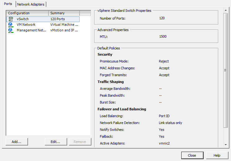
A single ESXI server can have a mixture of Standard vSwitches and Distributed vSwitches. A single vSwitch has a default of 120 logical ports. However, a vSwitch can be configured with up to 1,016 active ports. A single virtual machine will use one port on the vSwitch. A logical port on the vSwitch is also a member of a port group, which we’ll discuss later in this chapter. If you choose the standard defaults during the installation of ESXi, your initial vSwitch and vswif interfaces will already have been created for you.
Create a vSwitch and assign key configuration properties as follows:
Log in to the vCenter server and select the ESXi Host from the inventory list.
Select the Configuration tab from the right window pane and navigate to Networking. Any current network configurations will be displayed. Click the Add Networking link to create a new virtual switch.
Three options will be presented. Choose the default option, Virtual Machine, which allows you to add a labeled network for virtual machine traffic (Figure 3-4). Click Next to continue.

Select “Create a virtual switch” (Figure 3-5). A new vSwitch can be created with or without Ethernet adapters assigned to it.
If the vSwitch is configured without network adapters, all traffic will be confined to that vSwitch itself. Traffic on each of the virtual machines on the same switch will be isolated from other virtual machines and vSwitches.
A vSwitch that is configured with an Ethernet adapter will communicate with other physical hosts or virtual machines on its network. However, it can be isolated from other networks by using VLAN tagging.
Click Next to continue.
The Port Group Properties section allows you to configure the network label (Figure 3-6). This is used to identify the network and will be used by the virtual machine to associate itself with that specific network. Optionally, if you are using VLANs in the physical network, you can specify a VLAN ID between 1 and 4094. This can generally be left blank, but check with your network administrator.
Click Next to continue.


3.3. Removing a Virtual Switch
Solution
Use the vCenter to remove the vSwitch.
Discussion
Removing a vSwitch is simple with vCenter. However, it may disrupt your network; therefore, you should take precautions before removing a vSwitch that has virtual machines attached to it. Those virtual machines will need to be moved to another vSwitch in order to maintain their connectivity on the physical network.
Follow these steps to remove a vSwitch using vCenter:
Log in to the vCenter server and select the ESXi host from the inventory list.
Select the Configuration tab from the right window pane and navigate to Networking.
All configured virtual switches will be displayed in the Network window. Identify the vSwitch to be removed and click the Remove link above it (Figure 3-7).

3.4. Adding VMotion to Enable Virtual Machine Migration
Solution
Use the vCenter client to create a vSwitch attached to a VMkernel port and to enable VMotion.
Discussion
VMotion allows you to migrate virtual machines between ESXi hosts without taking down the virtual machines or ESXi hosts. This is called migrating. The migration uses a VMkernel port.
We looked briefly at VMkernel ports in Chapter 2, during our discussion of the configuration and setup of such ports for iSCSI and NFS traffic. ESXi3 uses a VMkernel port to handle all network based traffic for software iSCSI, VMotion, and NFS, because these technologies are network-based and can use the same VMkernel.
However, you can also configure a VMkernel port with support for VMotion. Some architectural restrictions should be observed to make VMotion work, though:
VMotion is designed to allow migration between similarly configured ESXi hosts. For example, CPU types must be compatible, and migration doesn’t work between AMD and Intel processors.
Typically, the VMkernel port that has VMotion configured will be on an isolated network away from all other traffic. This ensures that the complete network is available to transfer the necessary data while the migration is taking place.
VMkernel ports can be configured in the vCenter or via the command line. We will show you only how to use the vCenter client. If you read the recipes in Chapter 2 on configuring NFS and iSCSI, you will notice that the following steps are similar, but add the use of VMotion:
Log in to the vCenter server and select the ESXi host from the inventory list.
Select the Configuration tab from the right window pane and navigate to Networking. Any current network configurations will be displayed. Click the Add Networking link to create a new virtual switch.
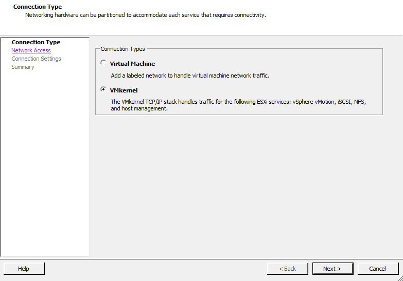
Three options will be presented. Choose the VMkernel option, which allows you to add a VMkernel port to handle TCP/IP traffic for VMotion, NFS, or iSCSI (Figure 3-8). Click Next to continue.
Select “Create a vSphere standard switch” and select the vmnic that will be used to handle the VMotion traffic. Details about the configuration will be presented in the Preview window (Figure 3-9). Click Next to continue.

The Port Group Properties section allows you to configure the network label, which is used to identify the network. It’s extremely important to use the exact same naming scheme on all your ESXi Servers to ensure that VMotion will initiate smoothly, remembering that network labels are case sensitive. If you are using Enterprise or higher licenses you can take advantage of Host Profiles to create a standardized network profile.
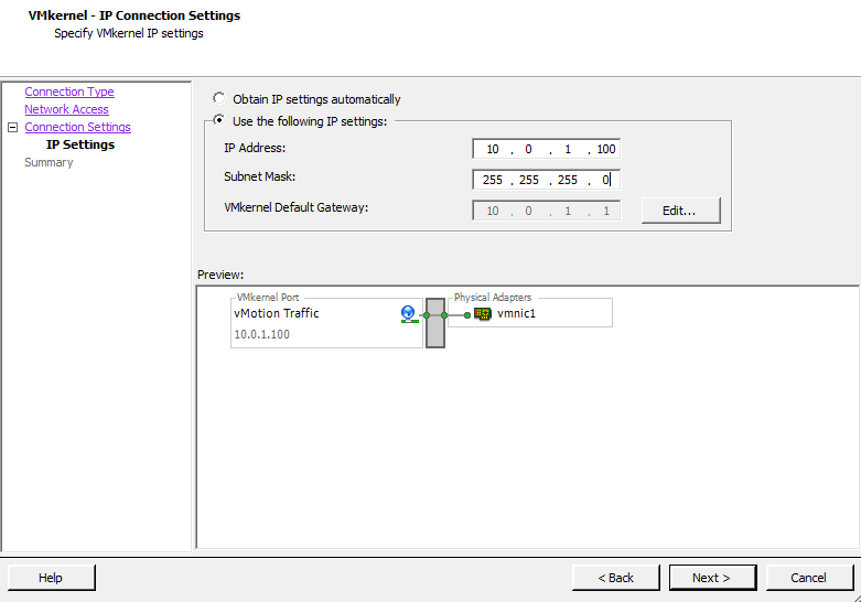
If VLANs are used on your network, enter the relevant information in the VLAN ID field. The step that configures a VMkernel for VMotion is also done here: “Use this port group for VMotion” must be checked and enabled. This allows the port group to advertise that it is going to handle VMotion traffic (Figure 3-10).

Fill in the IP Address and Subnet Mask fields. If there are more detailed network settings that need to be configured, such as gateways, routing, and DNS servers, click the Edit button to configure them. Save your changes by clicking OK, and click Next to continue (Figure 3-11).
View the summary on the Read to Complete screen and click Finish to finalize the configuration.
See Also
3.5. Modifying the Speed of a Network Adapter
Solution
Modify the network adapter’s properties in the vCenter.
Discussion
The vCenter offers control over a much smaller set of features on the physical adapter than you can control using command-line tools. However, vCenter does let you change the port speed of specific network adapters.
To configure your network adapter’s speed:
Log in to the vCenter server and select the ESXi host from the inventory list.
Select the Configuration tab from the right window pane and navigate to Networking. The current network configurations will be displayed.
Click the Properties link of the vSwitch that you wish to modify (Figure 3-12).

A new window will appear. Click the Network Adapters tab. From here, select the network adapter you wish to modify and click the Edit button.
A dialog box pops up allowing you to change the speed (Figure 3-13). Make your choice and click OK.

3.6. Choosing Network Elements that Protect Security
Problem
You want to make sure that the network tying your ESXi and virtual servers reflects your site’s needs and matches up with the security on your physical networks.
Solution
Examine the different security measures available in the ESXi network and create the appropriate architecture or firewalls.
Discussion
Securing your virtual network is just as important as securing the physical network to which your ESXI servers are connected. A virtual network may be subjected to the same attacks as a physical network. Virtual machines that are isolated from a physical network could even be targets of attacks from other virtual machines within the same ESXi network, so it’s important to take these things into consideration when planning your ESXi network configuration. In general, the security measures you use on your physical network should be replicated on your virtual network.
Within the ESXi network, virtual machines that are connected on separate network segments are isolated from each other, so they cannot read from, write to, or communicate with virtual machines on a separate network unless the ESXi network specifically enables such communication through vSwitches.
Some ways to add additional security are:
Keep virtual machines isolated by using separate physical network adapters for each internal ESXi network. This setup is the most secure one, because you are not sharing virtual machine traffic over the same physical network adapter.
For example, your physical network might have an external DMZ and an internal network. By connecting those separate physical networks to separate network adapters in ESXi, you physically separate the traffic. In contrast, putting those networks on a single network adapter would lead to the routing of internal and external traffic over the same network adapter inside ESXi, which could make the entire internal network just as vulnerable as your DMZ. Minimizing the potential attack locations will help you more easily defend your entire infrastructure.
Use software-based firewalls inside the ESXI server’s virtual network. Software-based firewalls can use Windows, Linux, or a virtual server appliance provided by a third-party vendor that sits between virtual machines.
Create virtual LANs (VLANs). ESXi fully supports VLAN tagging to isolate your network segments. Using VLANs allows you to route traffic from multiple networks on the same network, while keeping traffic separated by the VLAN ID.
3.7. Setting the Basic Level 2 Security Policy
Solution
Use the vCenter client to select the layer 2 security model that fits your environment.
Discussion
Port groups and vSwitches in ESXi have a layer 2 security policy with three different parameters you can control:
- Promiscuous mode
This option gives you access to the standard operating system feature of the same name. Promiscuous mode allows the virtual machine to receive all traffic that passes by on the network.
Although this mode can be beneficial for an administrator tracking network activities, it’s a very insecure operation mode because users can see packets on the network that are designated for other systems. In other words, if enabled, it would be possible for virtual machines to see other virtual machines’ traffic on the same network.
Therefore, by default, this option is set to Reject. Each virtual machine on the ESXI server receives only traffic directed to it.
- Forged transmits
This option is set to Accept by default, meaning that the ESXI server does not compare source IP addresses and MAC addresses. However, setting this to Reject causes the ESXI server to compare the source MAC address being transmitted by the operating system with the effective MAC address for its adapter.
- MAC address changes
This option is set to Accept by default, meaning that the ESXI server accepts irequests to change the MAC address associated with the sender. This affects traffic that the virtual machine receives.
If you are worried about MAC address impersonations, this can be set to Reject. However, ESXi will not honor requests to change the effective MAC address to anything other than the original MAC address. More information on this setting can be found in the ESXi documentation.
You can change these three settings using the vCenter as follows:
Log in to the vCenter server and select the ESXi host from the inventory list.
Select the Configuration tab from the right window pane and navigate to Networking. Any current network configurations will be displayed.
Click the properties link of the vSwitch that you wish to modify (Figure 3-14).

Select the vSwitch or port group that you wish to modify and click the Edit button (Figure 3-15).
A new pop-up window will appear. Click the Security tab to change the security policy settings (Figure 3-16).

3.8. Ethernet Traffic Shaping on Standard vSwitches
Solution
The ESXI server offers traffic shaping under the administrator’s control.
Discussion
The ESXI server can throttle and shape network traffic by adjusting three outbound characteristics:
- Average bandwidth
The number of bits per second to allow across the vSwitch, averaged over time.
- Peak bandwidth
The maximum amount of bandwidth in kilobits per second (Kbps) the vSwitch or port group can handle. If the traffic exceeds the peak bandwidth specified, the packets will be queued for later transmission. If the queue is full, the packets will be discarded and dropped.
- Burst size
The maximum number of bytes that the port is allowed to burst. If the packet exceeds the burst size parameter, the remaining packets will be queued for later transmission. If the queue is full, the packets will be discarded and dropped. If you set the average and the peak, this is a multiplicative factor that helps to determine how long the bandwidth can exceed the average at any rate before it must come back down to the average. The higher the bandwidth goes, the less time it can stay there with any particular burst size.
These values can be configured using the vCenter client on a specific port group within the vSwitch. Bandwidth shaping in ESXi is currently supported only on outbound traffic; these characteristics are ignored for inbound traffic.
To make changes to the traffic shaping policy:
Log in to the vCenter server and select the ESXi host from the inventory list.
Select the Configuration tab from the right window pane and navigate to Networking. Any current network configurations will be displayed.
Click the properties link of the vSwitch you wish to modify (Figure 3-17).
Select the vSwitch or port group you wish to modify and click the Edit button (Figure 3-18).

A new pop-up window will appear. Click the Traffic Shaping tab to change the policy exceptions (Figure 3-19).

Notice that the traffic shaping status is disabled by default. When this is disabled, you will not be able to make any changes to the various settings. To enable it, select Enabled from the status drop-down box, and the three configurable options will become available for you to modify to suit your needs.
The traffic shaping policy is then applied to each individual virtual adapter that is attached to the port group (not to the entire vSwitch).
3.9. Load Balancing and Failover
Problem
You want to set up multiple network adapters on a vSwitch to perform load balancing and support failover.
Solution
Set up load balancing and failure detection policies within your ESXi network.
Discussion
Load balancing helps you distribute traffic evenly among network adapters, whereas failover protects you in case adapters or upstream network elements stop working. This can be particularly useful when setting up a service console network to appease ESXi’s redundancy requirements for the service console.
When determining the policies that will be applied to your vSwitch, you need to consider three things:
- Load-balancing policy
Determines how outbound traffic will be distributed between the network adapters assigned to the vSwitch. It’s important to understand that inbound traffic is not affected by this setting.
- Network failover detection policy
Determines how aggressively the server monitors links for failures.
- Network adapter order
Indicates which adapters are active and which are on standby.
The vCenter allows you to configure these options and a few related ones. By doing so, you can set up a load-balanced and failover-ready network within your ESXi environment:
Log in to the vCenter server and select the ESXi host from the inventory list.
Select the Configuration tab from the right window pane and navigate to Networking. Any current network configurations will be displayed.
Click the Properties link of the vSwitch you wish to modify (Figure 3-20).

Select the vSwitch or port group you wish to modify and click the Edit button (Figure 3-21).

A new pop-up window will appear. Click the NIC Teaming tab to change the policy exceptions (Figure 3-22).

From here, the configurable options include:
- Load balancing
Allows you to choose one of four load-balancing methods:
- Route based on the originating virtual port ID
Choose an uplink based on where the virtual port’s traffic entered the switch. This is useful because each virtual machine has a vSwitch port ID assigned to it and the load is balanced based on that port ID. It also encompasses all protocols, including TCP and UDP.
- Route based on IP hash
Choose an uplink based on the hash of the IP address from the source and the destination, assuming the physical uplink switches have been configured to use 802.3ad/LACP. This method will have some additional overhead as the packets are handled not on the virtual machine layer, but instead on the physical network.
- Route based on source MAC hash
Choose an uplink based on a hash of the source MAC address. This option uses the virtual machine’s MAC address for the basis of its load balancing. This can cause problems if you change your virtual machine’s MAC address often or during a time when active network traffic is present.
- Use explicit failover order
Always use the first available uplink chosen in order from the list of active adapters. Using this option will not give you any load balancing, but it will give you failover capabilities.
- Network failover detection
Allows you to choose the method to be used for failover detection:
- Link status only
This method relies solely on the link status from the network adapter. It will detect an external networking error such as a bad cable or upstream switch failure, but not physical switch configuration errors.
- Beacon probing
This method sends out and listens for a beacon probe on all the NICs in the team. It will then use that information to determine whether there is a network failure. This option offers more end-to-end error checking.
- Notify switches
If this is set to Yes, in the event of a failure, the server will send out a notice to the upstream switches to update their lookup tables. This is desirable, but it should not be used in conjunction with Microsoft Load Balancing in unicast mode.
- Failback
Allows the originating physical adapter to fail back and take over the workload after a failure.
- Failover order
Here you can specify which physical adapters will handle the load and in which order they will do it. There are three different modes:
3.10. Enabling Jumbo Frames on a VMkernel for iSCSI
Problem
You want to improve performance through the use of Jumbo Frames on your software iSCSI network.
Solution
Using the console on the physical ESXI server, you can enable Jumbo Frames support.
Discussion
The Jumbo Frames feature increases the maximum frame size beyond the traditional 1,500 bytes, thus potentially reducing overhead and speeding up traffic on the link. Before enabling this feature, please check with your hardware vendor to ensure it is supported.
As of ESXi 5.0, the following operating systems support Jumbo Frames and have the enhanced vmxnet driver that supports the feature:
Microsoft Windows 2003 Server with Service Pack 2
Red Hat Enterprise Linux 5
SuSE Enterprise Linux 10
To enable jumbo frames you have to configure the VMkernel, the vSwitch, and each virtual machine on your server. This recipe and the next two cover these tasks.
Enable Jumbo Frames on a VMkernel port as follows:
Log in to the vCenter and select the ESXi host from the list.
Click the Configuration tab and click Networking.
Select the vSwitch that has the VMkernel Port on which you wish to enable Jumbo Frames on, Click the properties link on the right-hand side.
The vSwitch properties window will appear. Select the VMkernel Port under the Configuration section and click Edit.
A new window will appear. Under the General tab, look for the NIC Settings section which will allow you to set the MTU. This should be set to 9000 to enable Jumbo Frames. Once you make the selection, click OK and then OK again to return to the Networking section for the Host will appear as shown in Figure 3-23.

3.11. Enabling Jumbo Frames on a Standard vSwitch
Problem
You want to continue the task of enabling the use of Jumbo Frames by setting them up on your vSwitch.
Solution
Use the vCenter client and the vCenter to enable Jumbo Frames on a vSwitch.
Discussion
Enabling Jumbo Frames on a vSwitch is very similar to enabling the feature on a VMkernel port:
Log in to the vCenter and select the ESXi host from the list.
Click the Configuration tab and click Networking.
Select the vSwitch on which you wish to enable Jumbo Frames. Click the Properties link on the right-hand side.
Next, the vSwitch Properties window will appear. Select the vSwitch under the Configuration section and click Edit.
Next, a new window will appear. Under the General tab as shown in Figure 3-24, look for the NIC Settings section, which will allow you to set the MTU. This should be set to 9000 to enable Jumbo Frames. Once you make the selection, click OK and then OK again to return to the Networking section for the Host.

3.12. Enabling Jumbo Frames on a Virtual Machine
Solution
Using vCenter, you can enable Jumbo Frames on one or more virtual machines.
Discussion
To complete the configuration of Jumbo Frames, log in to the vCenter server and perform the following steps for each virtual machine on which you wish them to be supported:
Note
There is an issue with vSphere 5.x with Jumbo Frames and the vmxnet3 driver. If you are upgrading from ESXi/ESX 4.x you should keep the older version of the VMware tools. For more information, see the VMware KB entry (http://kb.vmware.com/selfservice/microsites/search.do?language=en_US&cmd=displayKC&externalId=2006277).
Select the virtual machine from the list presented to you and shut it down. Select the Summary tab, then select Edit Settings. You can also right-click on the virtual machine and select Edit Settings.
Select the network adapter from the hardware list and copy the MAC address that is displayed.
Now you must recreate the network adapter. Click the Add button and select Ethernet Adapter. Click Next. In the Adapter Type drop-down menu, select “Enhanced vmxnet.” Click Next and then Finish.
Now that the network adapter has been recreated using the enhanced vmxnet driver, you need to add the old MAC address. The new NIC is still highlighted at this point. Select the network adapter from the hardware list, change the MAC address radio button to Manual, and enter the old MAC address (if you used Ctrl-C to copy it previously, you can use Ctrl-V to paste it). Click OK to continue.
It’s important also to enable Jumbo Frames on the operating system running on the virtual machine. Power on the operating system and configure Jumbo Frames per instructions for that OS.
3.13. Changing the ESXi Host IP Address
Solution
In this recipe, we will outline the steps required to change the IP address of your ESXi host.
Discussion
In some situations you may be required to change the IP address of your ESXi host. For example, the network segment is being changed or you are doing a network restructure. Regardless, there are a few ways to reset and change the IP address. In this recipe, we’ll look at using the direct console user interface (DCUI), which is the main screen on the ESXi host system.
If the ESXi Host is attached to the vCenter server, you will need to remove that server via the vCenter client. If your ESXi Host is not connected to a vCenter server, then skip to step 2. Log in using the vCenter client and put your ESXi Host in maintenance mode. This will move the virtual machines to other ESXI servers within the cluster. If you are not using a cluster, you may have to manually vMotion all the virtual machines before putting the ESXi host in maintenance mode. Once the ESXi host is in maintenance mode, you can right-click and select Remove.
Connect directly to the DCUI of the ESXi host. Press F2 to log in to the system.
Select the Restore Network Settings option and press enter. A confirmation window will appear letting you know all settings will be restored to defaults. Press F11 to reset the ESXi host as shown in Figure 3-25.
Once completed, you can use the Configure Management Network to reconfigure the ESXi host with the new IP address, the DNS, and the hostname.

3.14. Using the Remote Command Line to Locate Physical Ethernet Adapters
Problem
You have to map the physical Ethernet adapters to the appropriate vmnic without using vCenter.
Solution
Use command-line commands to identify the physical Ethernet adapters.
Discussion
There may be a time when you need to identify the physical Ethernet adapters that exist in your ESXi host. This can also be accomplished in the vCenter by clicking on the ESXi host, clicking the Configuration tab, and then clicking Networking.
To do so, log in to the physical console of the ESXI server and
gain root privileges. Then run the esxcli network nic list command, which
displays all the physical Ethernet adapters along with their speeds,
drivers, MTUs, PCI devices, vmnics, link status, and
descriptions.
The following is an example of output on a server with 12 physical Ethernet adapters:
~ # esxcli network nic list

Name    PCI Device     Driver  Link  Speed  Duplex  MAC Address         MTU
------  -------------  ------  ----  -----  ------  -----------------  ----
vmnic1  0000:001:00.0  r8168   Down      0  Half    54:04:a6:48:7a:fd  1500

vmnic2  0000:003:05.0  r8169   Up     1000  Full    00:14:d1:1e:fe:f6  1500

~ #
(The description field is cut off in this example in order to fit
the output on the page.) You can then use the esxcli network vswitch standard list command
to see which vSwitches the Ethernet adapters (uplinks) are assigned
to:
~ # esxcli network vswitch standard list
vSwitch0
   Name: vSwitch0
   Class: etherswitch
   Num Ports: 128
   Used Ports: 3
   Configured Ports: 128
   MTU: 1500
   CDP Status: listen
   Beacon Enabled: false
   Beacon Interval: 1
   Beacon Threshold: 3
   Beacon Required By:
   Uplinks: vmnic2
   Portgroups: VM Network, Management Network
~ #
See Also
3.15. Changing the Ethernet Port Speed via the Command Line
Discussion
Although the port speed on a physical adapter is easily changed within the vCenter, it’s almost as important to understand how to change it using the command line in the event that the vCenter isn’t available. Here’s how:
Log in to the physical console of the ESXi host and gain root privileges.
List the available adapters by following the steps in the previous recipe, and make a note of the names of the adapters you wish to change.
Run the
esxcli network niccommand on each desired adapter to change the speed. For instance, the following command changes the vmnic1 port speed to 100MBps with the duplex set to full (you can instead set the duplex to half by specifying the-D halfoption):esxcli network nic set -S 1000 -D full vmnic1
To verify the changes, you can run the
esxcli network nic listcommand as outlined in the previous recipe:esxcli network nic list
See Also
Enabling TCP Segmentation Offload Support on a Virtual Machine
Solution
Follow these steps to enable TSO support; in addition, we will enable the enhanced vmxnet3 driver.
Discussion
By default VMware enables TSO (TCP Segmentation Offload) support on the VMkernel interface. However, it must be enabled on the virtual machine on which you wish to use this feature. The following operating systems that support the enhanced vmxnet network adapters.
Microsoft Windows 2003 Enterprise Edition with Service Pack 2 (32 bit and 64 bit)
Red Hat Enterprise Linux 4 (64 bit)
Red Hat Enterprise Linux 5 (32 bit and 64 bit)
SUSE Linux Enterprise Server 10 (32 bit and 64 bit)
The following steps are required to enable TSO support on a virtual machine. This can be replicated for each virtual machine. It’s also important to make sure the virtual machine is powered off when making these changes.
Log in to the vCenter server using the vCenter client and select the virtual machine you wish to modify.
Click the Summary tab and click Edit Settings.
Select the network adapter from the list and write down the MAC address.
Click Remove to remove the network adapter from the virtual machine.
Click Add and select Ethernet Adapter and click Next. In the Adapter Type group, select the enhanced vmxnet option.
Select the network setting and the MAC address the older network adapter was using and click Next.
Click Finish and then click OK.
Your virtual machine will require VMtools Version 8 or newer for TSO to work with the enhanced network driver.
Enabling Jumbo Frames on a Distributed Switch
Solution
Inside the vCenter server, you can modify the switch to support Jumbo Frames. Changing this setting is a must for iSCSI-based connectivity to ensure maximum performance of the iSCSI traffic.
Discussion
The following steps will enable Jumbo Frames on the distributed switch by modifying the MTU settings.
Log in to the vCenter server and select the Networking view.
Right-click the Distributed Switch you wish to modify and select Edit Settings.
Click the Properties tab, and select the Advanced option.
Finally, set the Maximum MTU to the largest size among all the virtual network adapters that are connected to the distributed switch.
When completed, click the OK button. Jumbo Frames will now be enabled for that distributed switch and its adapters.
Changing DNS Entries on the ESXi Host
Solution
Follow these quick steps to change the DNS servers your ESXI servers use.
Discussion
Log in to the vCenter and select the ESXi host from the list.
Click the Configuration tab and then select the DNS and Routing link on the left-hand side.
On the right side of the window, click the Properties link.
In the DNS configuration tab, enter the name and domain you wish to use.
Choose to use a static DNS entry or have one obtained automatically from the network.
Enter the domain on which the ESXi host will search for domains.
Creating a vSphere Distributed Switch
Solution
By following these steps you can create a vSphere Distributed Switch across your ESXi hosts, giving a unified network configuration.
Discussion
VMware introduced the Distributed Switch in ESX 4.x and has continued to improve this advanced switch with ESXi 5.0. By using Distributed Switches, you will create a unified switch configuration across all the hosts that are connected to that switch. This is very important when your virtual machines vMotion from server to server inside your cluster. In a traditional vSwitch configuration, you had to worry about the naming conventions of your vSwitches to ensure compatibility when doing vMotion. This is resolved when moving to a Distributed Switch, because it provides a common naming scheme across the ESXi hosts attached to the distributed switch.
Like traditional vSwitches, the Distributed Switches act like a hub, providing ports for the virtual machines to use. In addition, port groups are supported and, like a vSwitch, multiple network adapters are used as uplinks to the core network. In ESX 4.x, VMware started to support third-party switches, such as the Cisco 1000v, which uses the Distributed Switch API to provide additional features.
The following steps create a basic Distributed Switch. You will need to be running vCenter Server in order to create a Distributed Switch. In addition, once the Distributed Switch is created, you can add ESXi hosts to the switch.
Log in to vCenter and navigate to the Network view.
Right-click the Datacenter on which you wish to deploy the Distributed Switch and select New vSphere Distributed Switch. A new window will appear, allowing you to select from three different types of switches (Figure 3-26).
- vSphere Distributed Switch Version: 4.0
Supports ESX 4.0 and later
- vSphere Distributed Switch Version: 4.1.0
Supports ESX 4.1 and later
- vSphere Distributed Switch Version: 5.0
Supports ESX 5.0 and later (the default option)
It’s important to select the Distributed Switch that will be most compatible with the versions of ESXi that you are running.
Once you have selected the switch version, click Next.
In the Name area, enter the name for the Distributed Switch (Figure 3-27). Next, select the number of uplinks you plan to use with your Distributed Switch. The uplink ports should be available vmnic uplinks on each ESXi host. Once completed, click Next.
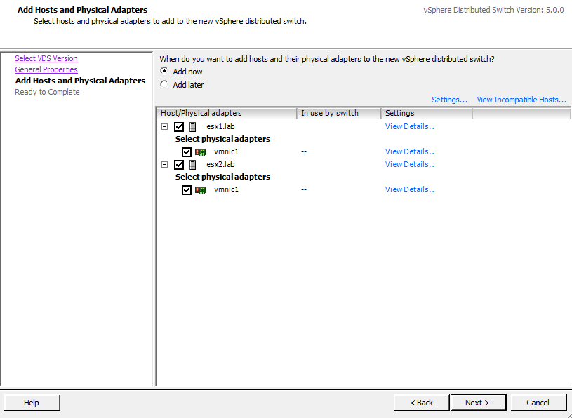
Next, assign the new Distributed Switch to the ESXi hosts and select the available network adapters. In our example we’ve assigned this switch to multiple ESXi hosts and assigned vmnic1 as one of the uplinks (Figure 3-28).
Click Next, and finally click Finish to create the new distributed switch.