3
Image Formation
Almost any lens that can be attached to a lens board, including a pinhole aperture, can be used on a view camera, but for most picture-taking situations lenses specifically designed for view cameras should be used. Considering the many ways in which lenses can differ, photographers often have little specific information about the lenses that they purchase and use. Not infrequently, the focal length and f-number of the maximum aperture are the only quantitative information marked on the lens barrel (with the full set of f-numbers and shutter speeds appearing on the shutter housing). Since relatively few photographers are prepared to conduct comprehensive lens tests, they tend to be influenced in their choice of lenses by recommendations of others and the manufacturers’ advertising claims. Although the major lens manufacturers do make testing and performance data available in their technical publications, some of the characteristics of the images formed by view camera lenses are difficult to document in terms that are meaningful to photographers who have no knowledge of optics. A basic knowledge of image formation is also helpful in understanding the limitations of view camera swings, tilts, and other adjustments to prevent unnecessary loss of quality of the optical image.
Some of the more significant ways in which the images formed by different lenses may vary are image size, image illumination at the maximum aperture, variations of illumination from the center to the edges of the film, image definition at the center and edges of the film, image definition when focused on near and far object distances, and accuracy of the image with respect to shape, color, and contrast.
3.1 Image Formation with a Pinhole
The simplest method for forming an optical image is with a pinhole in a thin sheet of opaque material. The pinhole can be thought of as transmitting only a single ray of light from each point on the subject, which, since light travels in a straight line in air, can strike only one position on a ground-glass viewing surface or piece of film placed behind the pinhole. The size of the inverted image increases with the distance between the pinhole and the ground glass or film, as shown in Figure 3-1. Instead of a single ray of light, the pinhole actually transmits a very narrow beam of light, one that has the same diameter as the pinhole, from each object point. It would seem logical that the sharpness of the pinhole image would vary inversely with the size of the pinhole, but for a given pinhole-to-film distance there is an optimum pinhole size. If the pinhole is made larger than the optimum size, it transmits too large a beam of light, which reduces image sharpness. If the pinhole is made smaller than the optimum size, it causes the narrow beam to spread out (somewhat like water from the nozzle on a garden hose) due to a phenomenon known as diffraction, which also reduces image sharpness.
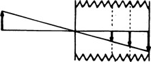
Figure 3-1
The size of the inverted image formed with a pinhole increases with the pinhole-to-film distance.
Images formed by pinholes are not good enough to compete with those formed by photographic lenses, although one may have a moment’s pause in identifying comparison photographs made with a pinhole and a soft-focus portrait lens (Figure 3-2). The image sharpness produced with a pinhole of optimum size used with a 4 × 5-in. or larger film is comparable to that produced with a professional soft-focus portrait lens used at the maximum aperture. Pinhole photography is introduced here because of the simplicity of image formation with pinholes, which makes it easier to understand the more complex process of image formation with lenses.
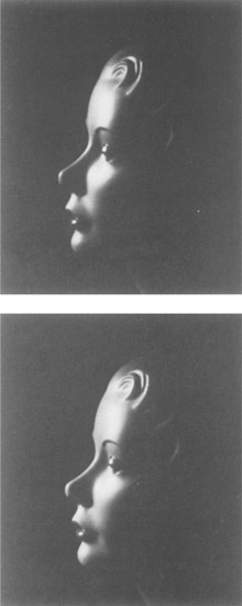
Figure 3-2
Photographs made with a pinhole aperture [top) and a soft-focus portrait lens [bottom).
Because pinholes produce images with nearly uniform sharpness for objects ranging in distance from miles to inches from the camera, many photography students, amateur photographers, and others have developed an interest in experimenting with pinhole photography and have produced many fascinating pinhole photographs. View cameras are well suited to pinhole photography since it is easy to attach a pinhole made in a small piece of thin, opaque material over an opening in a cardboard lens board. The distance between the pinhole and the film can be altered easily to change image size and angle of view, and sheet-film holders enable one to make as many different exposures as desired.
The diameter of a pinhole of optimum size varies primarily with the pinhole-to-film (or -image) distance. Optimum pinhole diameters are listed in Table 3-1 for image distances from 1 in. to 16 in. The corresponding f-numbers are also listed to assist in determining exposure times. If an exposure meter is used and the f-number scale does not include such large f-numbers, the exposure time for a smaller f-number should be multiplied by 4 each time the f-number is doubled until the desired f-number is reached, for example, 1/15 sec. at f/32 corresponds to ¼ sec. at f/64 and 1 sec. at f/128. With exposure times longer than 1 sec., it may be necessary to increase the indicated exposure time to compensate for reciprocity effects, a factor that will be discussed in Chapter 8, Exposure Meters.
Comparison pinhole images made with three different-size pinholes (optimum size, one-half optimum size, and two times optimum size) and an image made with a photographic lens on an 8 × 10-in. view camera are shown in Figure 3-3. The three pinhole prints were cropped to permit a side-by-side comparison, but the images are the same size as in the uncropped photograph made with the lens. One can see that the pinhole image becomes less sharp when the pinhole is either larger or smaller than the optimum size. Also, although the sharpest pinhole picture has good detail, it appears soft in comparison with the image made with the view camera lens.
Diffraction affects images formed with lenses as well as those formed with pinholes, although lens manufacturers normally do not equip their lenses with diaphragms that can be stopped down so far that diffraction produces an obvious degradation of the image. Some 35-mm camera lenses are designed so that they cannot
Table 3-1 Optimum Pinhole Diameters for Different Pinhole-to-Film Distances
| (Distance) f | (Distance) D | (f-Number) f-N |
|
|
||
| 1 in. | 1/140 in. | f/140 |
| 2 in. | 1/100 in. | f/200 |
| 4 in. | 1/70 in. | f/280 |
| 8 in. | 1/50 in. | f/400 |
| 16 in. | 1/35 in. | f/560 |
![]()
![]()
f−N = f/D
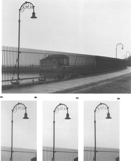
Figure 3-3
(A) Photograph made with a lens on an 8 × 10-in. view camera. Three additional photographs were made using different-size pinholes, and an area on the right side was cropped in printing to facilitate comparing image sharpness. The pinhole sizes were (B) one-half the optimum diameter, (C) the calculated optimum diameter, and (D) two times the optimum diameter.
be stopped down beyond f/16, to avoid an objectionable loss of definition. Comparable f-numbers for other format cameras are:
- f/32 for 2 ¼ × 2¼ in.
- f/64 for 4 × 5 in.
- f/128 for 8 × 10 in.
- f/256 for 16 × 20 in.
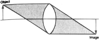
Figure 3-4
Image formation with a positive lens.
3.2 Image Formation with a Simple Lens
Positive lenses produce images by refracting or changing the direction of light so that all rays of light falling on the front surface of the lens from each object point converge to a point behind the lens, as shown in Figure 3-4. If the object is at infinity (or for practical purposes, at a very large distance), the light rays will enter the lens traveling parallel to each other, and the image point formed where they come to a focus is referred to as the principal focal point. For conventional photographic lenses, the approximate focal length can be determined by measuring the distance from the center of the lens to the principal focal point, or the distance from the center of the lens to the ground glass when a camera is focused on a distant object. The size of the image of a given object formed with a lens will be the same as the image formed with a pinhole when the distances from the lens and pinhole to the object and to the film are the same, as shown in Figure 3-5. Since the lens brings all the rays of light in the cone of light transmitted by the lens to a focus for each object point, a sharp (in-focus) image will be obtained only when the film is at an appropriate distance from the lens, determined by the focal length of the lens and the object distance.
3.3 Lens Terminology
The following 17 terms refer to important physical and optical features of photographic lenses.
Spherical Surfaces
The surfaces of most photographic lenses are either flat or spherical (Figure 3-6). Cross-section drawings of lenses show the curved surfaces as parts of circles, but on the actual lenses they are parts of spheres. Aspherical surfaces (curved surfaces that are not spherical) are used in some photographic lenses.
Center and Radius of Curvature
If the lens surface is extended to form a complete sphere, the center of the sphere and the radius of the sphere are referred to as the center of curvature and the radius of curvature, respectively (Figure 3-7).
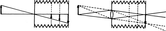
Figure 3-5
Image size is determined by the position of the film.

Figure 3-6
Curved lens surfaces as parts of spheres.
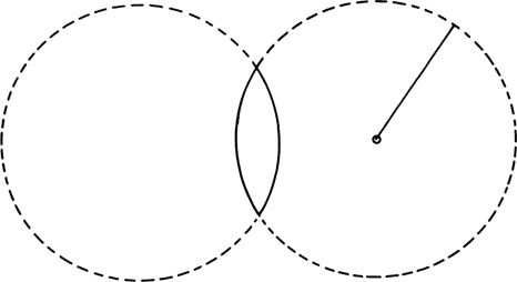
Figure 3-7
Center and radius of curvature.
Positive Lenses
Positive lenses are thicker in the center than at the edges. One surface of all positive lenses must be convex. The other surface can be convex, plane, or concave. If the second surface is concave, it must have a larger radius of curvature than the convex side. The three basic types of positive lenses are shown in Figure 3-8.
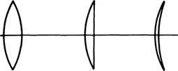
Figure 3-8
Positive lenses.
Negative Lenses
Negative lenses are thinner in the center than at the edges. They are incapable of forming real images, that is, images that can be focused on a ground glass or film, but negative lenses are used in combination with positive lenses. The three basic types of negative lenses are illustrated in Figure 3-9.
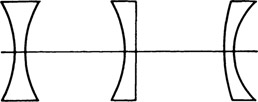
Figure 3-9
Negative lenses.
Lens Axis
The lens axis is a straight line through the centers of curvature of the lens surfaces (Figure 3-10). Two of the six basic types of lenses have only one center of curvature. With lenses having one plane surface, the lens axis is a line through the center of curvature perpendicular to the plane surface. When two or more elements are combined to form a compound photographic lens, the lens axes of the individual elements must coincide. Dropping a photographic lens may destroy this alignment, which in turn will affect image definition even though there is no outward evidence of damage to the lens.
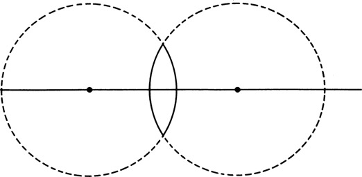
Figure 3-10
Lens axis.
Optical Center
The optical center of a single element or of a compound lens is a point on the lens axis through which every ray of light that passes is undeviated (Figure 3-11). That is, all rays of light that pass through the optical center leave the lens traveling in the same direction they entered, although they may be displaced laterally. The surfaces where undeviated rays enter and leave the lens are parallel to each other, so that for these particular rays the lens is acting like a piece of window glass with parallel sides.
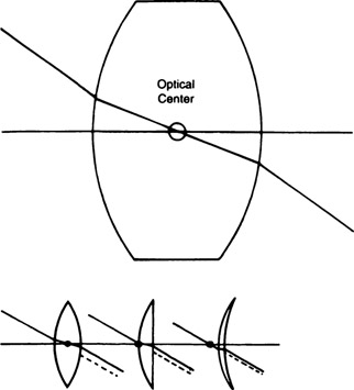
Figure 3-11
(Top) Any ray of light that passes through the optical center leaves the lens traveling parallel to the path of the entering ray. (Bottom) Locations of the optical center with lenses having different shapes.
Nodal Points
Nodal points are two points on the lens axis so located that every ray of light that passes through the optical center will enter the lens in the direction of one (the object nodal point) and leave the lens as if it came from the other (the image nodal point) (Figure 3-12).
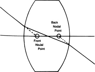
Figure 3-12
Using a ray of light that passes through the optical center, the nodal points can be located by extending the entering and departing segments in straight lines until they intersect the lens axis.
Nodal Planes
Nodal planes are planes through the nodal points, perpendicular to the lens axis (Figure 3-13). A knowledge of the location of nodal points and planes is useful in three ways. First, accurate measurement of distances, such as object and image distances and focal length, must be made to the appropriate nodal plane. Measuring to the physical center of the lens may introduce considerable error with some lenses. Second, it is desirable to have lenses tilt and swing about the rear nodal point to minimize the amount of refocusing and recomposing necessary after adjusting the lens. A practical method for locating the image nodal point is to focus the lens on a distant object and locate the point along the lens axis where pivoting the lens will not result in a movement of the image (Figure 3-14). Reverse the lens and repeat the process to locate the object nodal point. A simple nodal slide is shown in Figure 3-15 and a professional nodal slide is shown in Figure 3-16. If view cameras were provided with an adjustable pivot point and lens manufacturers would indicate the location of the back nodal point on their lenses, the pivot point could be aligned with the back nodal point so that the image would not shift laterally on the ground glass as the lens was swung (Figure 3-17). A similar adjustment would be needed for the tilt adjustment. Third, the concept of image formation is simplified with compound lenses by utilizing the nodal planes. Once the location of the two nodal
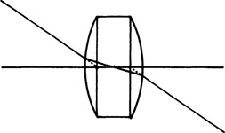
Figure 3-13
Nodal planes are located at the nodal points and are perpendicular to the lens axis.
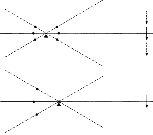
Figure 3-14
Determining the position of a nodal point by pivoting a lens at various points along the lens axis until the image of a distant object remains stationary.
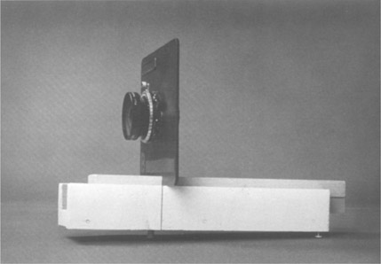
Figure 3-15
A simple nodal slide. The lens holder can be moved in the support so that the lens can be pivoted at various points along the lens axis.
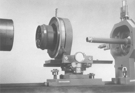
Figure 3-16
A professional nodal slide with a light collimator on the left, a device to pivot the lens at various points along the lens axis in the center, and a microscope to examine the aerial image on the right.
planes has been established, all glass surfaces can be disregarded even if the lens contains many elements.
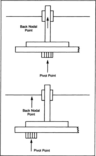
Figure 3-17
Ideally, view cameras would permit the lens pivot point to be adjusted so that all lenses could be rotated about a point directly in line with the back nodal point of the lens.
Object and Image Distances
When precision is not required for the determination of object and image distances, object distance can be measured from the object being photographed to the center of the lens and the image distance from the center of the lens to the ground glass, after focusing the image. When greater accuracy is required, however, the object distance should be measured from the object to the front nodal plane and the image distance from the back nodal plane to the in-focus image, both measurements being made in a direction parallel to the lens axis (Figure 3-18). For most picture taking with conventional view camera lenses, the errors introduced by making measurements to the center of the lens rather than the nodal planes will not be significant. However, it should be noted that with some lenses of special design, such as telephoto lenses and reversed-telephoto wide-angle lenses, which are used primarily on small-format single-lens reflex cameras, the nodal planes tend to be located in front of the lens and behind the lens, respectively. Although lens manufacturers do not indicate the locations of nodal planes on their lenses, the location of the back nodal plane of any lens can be determined by focusing the lens on infinity, or a very distant object, and measuring one focal length forward from the ground glass. The location of the front nodal plane could be determined by turning the lens around and repeating the process.
Principal Focal Point
The principal focal point is the position of best axial focus for an infinitely distant object. Actually, there are two principal focal points. The first is in the front space (normally the object side of the lens) and the second is in the back space. Where the term is used without modifiers, it refers to the back principal focal point (Figure 3-19).

Figure 3-18
For an object point that is not on the lens axis, object and image distances are measured in a direction perpendicular to the nodal planes (and parallel to the lens axis).
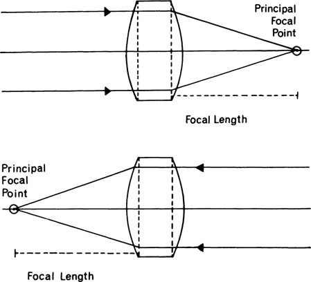
Figure 3-19
Principal focal point and focal length with a distant object to the left of the liens (top) and with a distant object to the right of the lens (bottom).
Focal Length
The focal length is the distance from the emergent (image) nodal point to the principal focal point. Every lens has two focal lengths, the front and the back, corresponding to the two principal focal points (Figure 3-19). The two focal lengths are equal. Lenses of different focal lengths produce different-size images and different angles of view when used with the same film format. The recommendation for general-purpose photography is that the focal length of the lens should be approximately equal to the diagonal of the film, but extreme deviations from this rule are frequently required for various types of photographs.
Angle of View
The angle of view is the angle formed by lines from the image nodal point to two opposite corners of the film with the film located one focal length from the image nodal point (Figures 3-20 and 3-21). An angle of 53° is formed when the lens focal length is equal to the film diagonal. Some lens manufacturers publish two values for the angle of view, 27° × 40°, for example, one based on the short dimension of the film and the other on the long dimension, rather than the film diagonal. Angle of view is determined solely by focal length and film size and should not be confused with the following terms applied to the covering power of lenses.
Circle of Good Definition
The circle of good definition is a circular area in the image plane within which the lens is capable of forming an image having acceptable definition. The diameter of the circle of good definition of a lens must be at least as large as the diagonal of the film if the camera has no movements but appreciably larger when adjustments are to be used (Figure 3-22). Shifting the lens or back vertically or horizontally, or tilting or swinging the lens, will throw the circle of good definition off center relative to the film, and image definition will not be satisfactory on any part of the film outside the boundaries of the circle. Tilting and swinging the back do not appreciably alter the relative positions of the circle of good definition and the film. The only conditions under which the circle of good definition is actually circular in shape in the film plane is when the lens board and film plane are parallel to each other. When they are not parallel, the “circle” of good definition becomes elliptical.
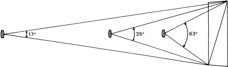
Figure 3-20
Angle of view with different focal length lenses and constant film size.
Four factors affect the size of the circle of good definition (Figure 3-23). First, with lenses of conventional design, the diameter of the circle of good definition is approximately equal to the focal length (Figures 3-23 and 3-24). Second, stopping a lens down increases the size of the circle of good definition with most lenses. With an 8-in. focal length lens, the diameter of the circle may increase from 8 in. at the largest aperture to 9 or 9½ in. at the smallest aperture (Figures 3-23 and 3-25). Third, lens design affects the ratio of the circle of good definition to the focal length. The diameter of the circle of good definition is larger than the focal length with wide-angle lenses and smaller than the focal length with telephoto lenses. Fourth, since the usable light transmitted by a lens is projected toward the film in the shape of a cone, the farther the image is formed behind the lens, the larger the circle of good definition will be. Thus, an 8-in. lens that has an 8-in. diameter circle of good definition when photographing distant scenes will have twice as large a circle when photographing a closer object that requires double the bellows extension (Figures 3-23 and 3-26).
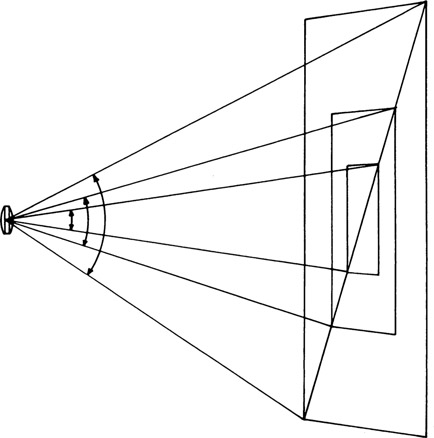
Figure 3-21
Angle of view with different film sizes and constant lens focal length.
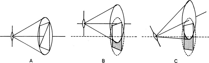
Figure 3-22
Position of the circle of good definition in relation to the film with the lens zeroed (A), with the lens raised (B), and with the lens tilted (C).
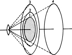
Figure 3-23
Factors affecting the size of the circle of good definition are stopping down (1 and 2), focusing on a closer object (1 and 4), substituting a wide-angle lens with the same focal length (1 and 3), and substituting a longer focal length lens of conventional design (1 and 4).
Angle of Coverage
The angle of coverage is the angle formed by lines connecting the image nodal point to opposite sides of the circle of good definition, or the angle of the cone of usable light transmitted by the
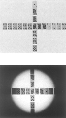
Figure 3-24
Photographs made with a lens having a large enough circle of good definition to cover the entire film area and a lens having too small a circle of good definition for the film.
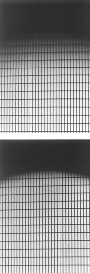
Figure 3-25
Edges of the circles of good definition and illumination with the lens diaphragm wide open [top) and stopped down [bottom).
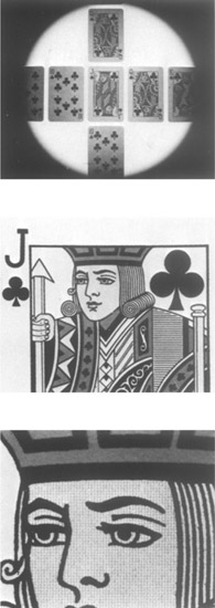
Figure 3-26
Three photographs made with the same lens, with the camera moved progressively closer to the subject. The circle of good definition increases in size as the lens-to-film distance is increased to keep the image in sharp focus. At the intermediate position, the circle of good definition of the conventional 2-in. focal length lens is large enough to cover 4 × 5-in. film. At the closest position, the circle is large enough to permit moderate use of the tilt, swing, lateral shift, and rising-falling adjustments on the camera.
lens (Figure 3-27). Thus, angle of coverage and circle of good definition both measure the covering power of lenses. Observe, however, that the angle of coverage is altered by only two of the four factors that determine the size of the circle of good definition. Changes in lens-to-film distance, due to either a change in focal length or a change in subject-to-lens distance, do not affect the angle of coverage.
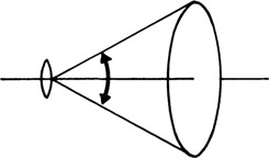
Figure 3-27
Angle of coverage.
Since the standard angle of view (when the focal length is equal to the film diagonal) is 53°, the angle of coverage of a lens intended for general-purpose photography must be at least 53°, and larger if camera adjustments that alter the position of the lens axis in relation to the film are to be used. Information concerning the angle of coverage and the circle of good definition for specific lenses is available from some lens manufacturers, but since the values of these lens properties vary with the aperture, a person who is considering purchasing a lens should determine if the data apply to the lens wide open or stopped down (see Tables 12-4 to 12-8).
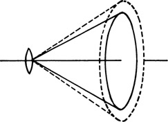
Figure 3-28
Circle of illumination (dashed circle) and circle of good definition (solid circle).
Circle of Illumination
The circle of illumination is the circular area in the image plane formed by the entire cone of light transmitted by the lens. Although the circle of illumination is always larger than the circle of good definition, the difference in size of the two circles varies with lenses and as a given lens is stopped down (Figure 3-28). Poor image definition in the zone outside the circle of good definition but inside the circle of illumination normally makes that area unusable, but if parts of the subject represented in this zone are devoid of detail, such as blue sky or a plain background, an objectionable result is less likely. Shifting and tilting the lens move the circle of illumination in relation to the film (Figure 3-29) the same as they move the circle of good definition (Figure 3-22).
3.4 Image Formation with a Multiple-Element Lens
All view camera lenses contain multiple elements. The high-quality view camera lens illustrated in Figure 3-30 contains a total of six positive and negative elements. For some purposes, as when comparing basic types of lenses (such as normal, telephoto, and wide-angle) and when discussing lens design with respect to lens aberrations, it is important to examine the arrangement of the individual elements in lenses. For noting the relationships between object and image distances and object and image sizes for a given lens or for lenses having different focal lengths, the lens diagrams can be simplified to three straight lines—a horizontal line representing the lens axis and two vertical lines representing the nodal planes. If the separation between the nodal planes is small, as it usually is, and great precision is not required, they can be combined into a single vertical line.
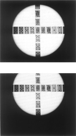
Figure 3-29
Positions of the circle of good definition in relation to the film with the lens adjustments zeroed and after lowering the lens with the rising-falling adjustment. The image moved down on the ground glass and up on the print.
3.5 Typical Image Formation Problems
Photographers are frequently faced with the need to anticipate such problems as these: How large an image can I obtain of a small object with a certain camera and lens? What focal length lens will I need to include all of a subject where the distance the camera can be placed from the subject is limited? How large a studio will I need to make full-length portraits with a certain camera and lens? What is the longest focal length lens I can use on a certain camera for photographing distant scenes? Photographers can determine the answers to such problems using several methods.
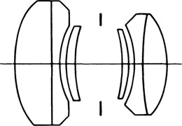
Figure 3-30
A high-quality general-purpose view camera lens that contains six elements.
The most obvious and direct method is to set up a camera in the actual situation, or as close an approximation to the actual situation as possible, and vary the appropriate factors to obtain the desired information. This experimental procedure is occasionally the most satisfactory method, but it is often difficult and time-consuming or the variety of equipment needed is not available. Two other methods will be presented—graphic drawings and lens formulas. Graphic drawings have the advantage of helping the photographer visualize the situation and the variables involved, whereas the lens formulas become more useful as clearer concepts of the process of image formation are formed.
3.6 Graphic Drawings
Up to now schematic drawings of image formation by lenses have been satisfactory to illustrate the basic concepts involved. We are now concerned with making drawings that are correct with respect to the size and position of the image under a specified set of conditions. If all the distances are small, we can make a full-size drawing, but as the distances increase, it becomes necessary to make the drawings to scale.
The following distances are involved in graphic drawings: focal length (f), object size (O), image size (I), object distance (u), and image distance (v). For the following example, let:
- Focal Length = 4 in.
- Object Distance = 8 in.
- Object Size = 4 in.
A scale of 1:4 will be used, reducing the actual dimensions on the drawing to f = 1, u = 2, and 0 = 1. Eight steps are involved in making the graphic drawing, as shown in Figure 3-31, after which we can determine the values for the two unknown factors—image distance and image size (the reproduction does not conform to the 1:4 scale of the original drawings):
- Draw a straight horizontal line to represent the lens axis.
- Draw a line perpendicular to the lens axis to represent the nodal planes. (The two nodal planes are combined for thin lenses, but separate nodal planes are drawn for thick lenses.)
- Place a mark on the lens axis 1 in. on each side of the nodal planes to represent the principal focal points.
- Place a mark 2 in. to the left of the nodal planes and 1 in. above the lens axis to represent a point on the object.
- Draw a ray from the object point straight through the optical center of the lens.
-
Draw a second ray from the object point parallel to the lens axis to the nodal planes, then through the back principal focal point. The image comes to a focus where the two rays intersect.
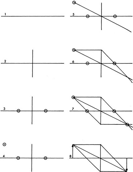
Figure 3-31 Procedure for making a graphic drawing.
- Draw a third ray from the object point through the front principal focal point to the nodal planes, then parallel to the lens axis. This ray is not essential but serves as a check on the accuracy of the position of the image.
- Draw a line from the object point perpendicular to the lens axis to represent the entire object and a line from the image point perpendicular to the lens axis to represent the corresponding image.
Measure the distance from the nodal planes to the image (2 in.) and the image height (1 in.), and multiply each by 4 to compensate for the scale. The image distance is thus found to be 8 in. and the image size 4 in. This, of course, is the situation where the object and image distances are equal and the image is the same size as the subject. Repeating this procedure for objects at different distances will produce images that are correct in size and position. An attempt to place the object at one focal length from the lens or closer will result in the rays leaving the lens traveling parallel or diverging, since it is impossible to obtain real images at these distances. The results of placing an object at one, two, three, four, and five focal lengths from the lens are illustrated in Figure 3-32. With the thick lens treatment, all rays from the object are drawn to the object nodal plane, and all rays to the image are drawn from the image nodal plane. Between the two nodal planes, all rays are drawn parallel to the lens axis (Figure 3-33).
Graphic drawings are not limited to determining image distance and image size. If the image distance and image size are known but the object distance and object size are unknown, the same procedure can be used to make a drawing. The principal focal points can also be located to determine the focal length, providing the sizes and distances for both object and image are known.
Angle of view can be determined by drawing a line of the appropriate length for the film diagonal through the back principal focal point perpendicular to the lens axis. Lines drawn from the ends of the film diagonal to the nodal points, as illustrated in Figure 3-34, will produce an accurate angle of view that can be measured with a protractor. (No scale compensation is necessary with angles.) Angle of view is defined for a distant object where the film is located one focal length behind the image nodal point. The effective angle of view that results when the camera is focused on close objects can be found by substituting the lens-to-film distance for the focal length on the drawing. The two angles can be drastically different, as shown in Figure 3-35.
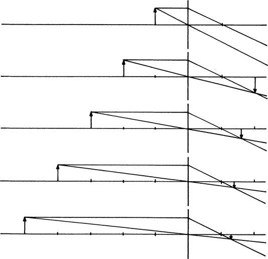
Figure 3-32
Graphic drawings with the object at one, two, three, four, and five focal lengths from the lens.
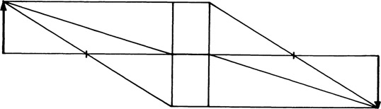
Figure 3-33
Graphic drawing with thick lens treatment.
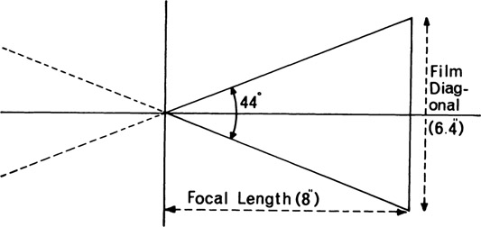
Figure 3-34
Drawing to determine the angle of view, utilizing film diagonal and focal length.
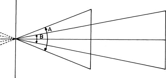
Figure 3-35
Angle of view (A) with film located one focal length behind the lens, and effective angle of view (B) with camera focused on near object.
3.7 Lens Formulas
Four lens formulas can be used to solve problems involving the five distances listed in the preceding section on graphic drawings. A sixth term, scale of reproduction (R), is added. Scale of reproduction is not a distance but a ratio of image size to object size (I/O). Although a total of only four terms appears in the formulas— focal length (f), object distance (u), image distance (v), and scale of reproduction (R)—problems involving image size or object size can be solved by substituting I/O for R in the appropriate formula. The four formulas follow, with a listing of the terms contained in each. There are three terms in each formula, but no two formulas contain the same terms. Therefore, to solve a problem in which the object distance and the focal length are known and the scale of reproduction is to be found, for example, the formula containing these three terms—u, f, and R—is selected. The values are substituted for the two known terms, and the formula is solved for the unknown term.
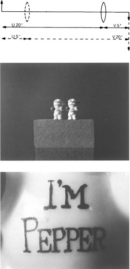
Figure 3-36
With a fixed distance between the subject and the film, in-focus images can be obtained with the lens in two different positions. In this example, the conjugate object and image distances are 5 in. and 20 in., and the scales of reproduction are 1:4 and 4:1.
| Formula | R | f | u | v |
|
|
||||
|
|
* | * | * | |
|
|
* | * | * | |
|
|
* | * | * | |
|
|
* | * | * | |
Formula 1 mathematically confirms two important relationships between object distance and image distance, which are referred to as conjugate distances. The first relationship is that as the object distance increases, the image distance decreases, as was shown graphically in the preceding section. With a 4-in. focal length lens, it is possible to have infinite combinations of values for u and v, but once a value is selected for either, there is only one value for the other. If u is 8, then v must be 8 also:
If u is increased to 12, then v decreases to 6:
The second relationship is that the object distance and the image distance are interchangeable. Changing the object distance in the preceding equation from 12 to 6 changes the image distance from 6 to 12. The significance of this is that images can be obtained with a lens in two different positions, keeping the subject and the film stationary, as in Figure 3-36. This situation is encountered most frequently in closeup work with the view camera (and in enlarging), as the bellows must be capable of being extended as far as the larger of the two distances. If the object and image distances are equal, however, there is only one position in which the lens will produce a sharp image. 111
Sample problem using the formula ![]() : A camera has a maximum bellows extension of 30 in. and is equipped with a 20-in. focal length lens. What is the minimum object distance the camera can be focused on?
: A camera has a maximum bellows extension of 30 in. and is equipped with a 20-in. focal length lens. What is the minimum object distance the camera can be focused on?

Formulas 2, 3, and 4 all contain the scale of reproduction and different combinations of two of the three terms—object distance, image distance, and focal length.
Sample problem involving the scale of reproduction: A camera has a maximum bellows extension of 20 in. and is equipped with an 8-in. focal length lens. What is the maximum scale of reproduction that can be obtained with this camera and lens? Since the three terms involved in the problem are image distance, focal length, and scale of reproduction, formula 3 is selected: