
2
View Camera Adjustments
2.1 View Camera Adjustments
The following view camera adjustments are illustrated in Figure 2-1:
- Focusing, which consists of changing the distance between the lens and the ground glass. It is accomplished by changing the position of the front and/or back runner on the monorail. Most cameras have both coarse and fine focusing capabilities. Coarse focusing is used when setting the camera up and when substituting a different focal length lens to quickly bring the image into approximate focus, and fine focusing is used to achieve critical focus before exposing the film.
- Back tilt, which is a rotation of the camera back around a horizontal axis. The back tilt is used to control the convergence of parallel vertical subject lines, as on a building, when tilting the camera up or down. Tilting the back also alters the angle of the plane of sharp focus in object space, but the back cannot be used for this purpose if it is needed to control image shape.
- Back swing, which is a rotation of the camera back around a vertical axis. The back swing is used to control the convergence of parallel horizontal subject lines, as on the side of a building that is at an angle to the camera such that one end of the building is farther from the camera than the other. In contrast to the treatment of vertical subject lines, it is seldom desirable to make receding parallel subject lines parallel in the photograph, although increasing and decreasing the rate of convergence of the parallel lines provides the photographer some control over the apparent distance between the near and far parts of the subject.
- Front tilt, which is a rotation of the lens board and lens around a horizontal axis. The front tilt is used to control the angle of the plane of sharp focus from top to bottom in vertical object space, as on the front of a tall building, or from front to back on a horizontal subject plane, such as railroad tracks. Since tilting the camera back also alters the plane of sharp focus, it is important to adjust the back tilt for image shape before tilting the front to alter the plane of sharp focus.
- Front swing, which is a rotation of the lens board and lens around a vertical axis. The front swing controls the side-to-side angle of the plane of sharp focus, and it should be adjusted after the swing position of the back has been established.
- Front vertical shift (or front rise-and-fall adjustment), which moves the image approximately the same distance in the same direction on the ground glass. Thus, the top of a tall building could be shown on the ground glass by shifting the lens upward with the camera level, as an alternative to tilting the entire camera upward, which would require readjusting both the back and front tilt adjustments.
- Front horizontal shift, which moves the image approximately the same distance in the same direction on the ground glass. It can be used, for example, to center the image of a painting that is being copied to avoid having to readjust the back and front swings, which would be required if the angle of the camera were changed.
- Back vertical shift (or back rise-and-fall adjustment), which in effect moves the image in the opposite direction the same distance
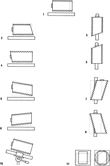
Figure 2-1 Basic view camera adjustments: (1) focusing, (2) back tilt, (3) back swing, (4) front tilt, (5) front swing, (6) front vertical shift, (7) front horizontal shift, (8) back vertical shift, (9) back horizontal shift, (10) pan-and-tilt head, and (11) reversible and revolving back.
on the ground glass. Thus, shifting the back down 2 in. is equivalent to shifting the front up 2 in. Also, the two movements can be combined when neither the front nor back can be shifted far enough to achieve the desired effect.
- Back horizontal shift, which in effect moves the image the same distance in the opposite direction on the ground glass. The effects of shifting the front and back in opposite directions are additive and can be used when neither can be shifted far enough to achieve the desired effect.
- Pan-and-tilt head, which allows the entire camera to be tilted up and down, rotated clockwise and counterclockwise, and panned through a 360° circle around a vertical axis. Pan-and-tilt heads are either an integral part of the camera or available as an accessory for approximately half of the various models of view cameras on the market. When this device is not provided with the camera, the camera normally is used with a tripod or camera stand that has a pan-and-tilt head.
- Reversible and revolving back adjustments, which allow the ground glass and film to be placed in either a vertical or horizontal format position. A full, or 360°, revolving back also allows angular croppings between the vertical and horizontal positions. Full revolving backs, however, require a larger bellows to prevent obstruction of light in the corners of the picture when the back is in an intermediate position.
2.2 Focusing Principles
Much of the quality and precision built into a camera by the manufacturer may be wasted by carelessness in the way the camera is used or a lack of knowledge of the principles involved. Because focusing a camera seems so simple and straightforward it is not always given the attention it deserves. Most cameras are designed so that the distance between the lens and the film can be adjusted to keep the image in sharp focus as the distance from the camera to the subject changes. The major exceptions are the inexpensive “fixed-focus” type of camera, which depends on a lens that has a fairly large depth of field to produce an image that will have acceptable sharpness for the uncritical viewer, and the specialized cameras designed to photograph objects at fixed distances from the camera, such as fingerprint and data-recording cameras.
To obtain sharp images of objects at long distances from the camera, the film must be positioned one focal length from the image nodal point of the lens. (With lenses of conventional design, the image nodal point is normally located between the center and the back surface of the lens.) The film will never be moved closer to the lens than this for focusing purposes. As the camera is moved closer to the object being photographed, the distance between the film and the lens must be increased to keep the image in sharp focus. The limit of this adjustment is reached with a view camera when the lens and the camera back are at the extreme ends of the camera bed or the bellows is fully extended (Figure 2-2).
Two-dimensional subjects provide the least complicated focusing situation. With the camera aligned so that the lens board and the ground glass are parallel to the subject, as when copying paintings, photographs, and documents, focusing on any part of the image should produce satisfactory focus for the entire image, assuming the lens is well corrected for aberrations (Figure 2-3). Shortcomings in craftsmanship and equipment may prevent optimum focus from being realized in practice. If the camera has been properly aligned, the major craftsmanship problem facing the photographer is to place the ground glass (or the lens) in the exact position that will produce the sharpest focus. Photographers have a tendency to overestimate their ability to do this. Experiments in which a person focuses repeatedly on the same subject have revealed that it is not uncommon for the focus to vary considerably. Photographers can check their own ability to focus consistently by focusing the camera, placing a fine pencil mark on the camera bed to indicate the position of the focusing adjustment, moving the adjustment and refocusing several times, each time marking the position on the bed. Consistency on one test situation does not guarantee accuracy of focus on all future photographs, especially where the light is dim and the subject has little detail, but a lack of consistency on the test should not be ignored (Figure 2-4). If the variation is measurable, the procedure should be repeated using a focusing magnifier to examine the image on the ground glass.
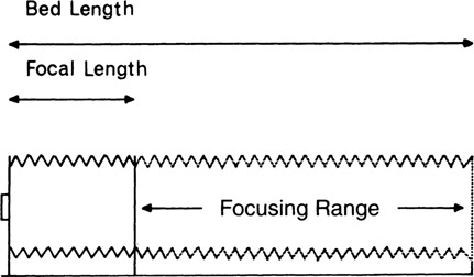
Figure 2-2
Limitations on lens-to-film distance with near and far objects.
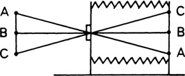
Figure 2-3
Focusing on a two-dimensional subject that is parallel to the lens board and the film, points A, B, and C of the subject all can be brought into focus in the film plane.
A too-strong magnifying glass, however, can cause the graininess of the ground glass to become so pronounced that it interferes with the ability of the photographer to focus on extremely fine detail. The graininess can be minimized by the application of petroleum jelly, oil, clear nail polish, transparent tape, or similar material to the ground side of the ground glass. It is advisable to treat only a small spot in the center, as treatment of the entire ground glass will cause the brightness of the image to decrease excessively toward the corners, making it difficult to evaluate the overall effect. Ground glass with a finely ground surface produces a similar effect. Complete elimination of the ground surface would enable the photographer to focus more precisely on the aerial image, but this technique requires hair-lines or other details on the surface of the glass so the eye can focus on the proper plane and would interfere with seeing the entire picture.
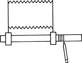
Figure 2-4
Checking focusing consistency.
Automatic focusing by electronic means is commonly found on 35-mm and other small-format cameras. A variety of autofocus (AF) systems have been introduced, the most common of which allows the photographer to select the subject area to be focused on by positioning the image of the object within a designated area in the viewfinder. The focus can be locked in by pressing lightly on the shutter release, which allows the angle of the camera to be altered to obtain a desired composition. This system would be inconvenient for view camera users, although a system that allows the photographer select the area to be focused on with a movable probe at the film plai or by selecting a position on a ground-glass grid (systems used on some view cameras for making exposure-meter readings at the film plane) is useful. Laboratory tests in which a number of people focused a lens repeatedly, visually and electronically, revealed less variation in the position of focus with the electronic method. There was less variation between individuals as well as for each individual.1 A comparison of the results of two methods of focusing is shown in Figure 2-5. Advances that have been made in automatic focusing systems since this test was conducted would certainly produce even less variability with the electronic system if the test were repeated today.
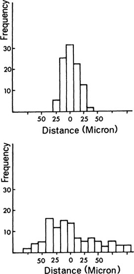
Figure 2-5
Histograms of electronic focusing (top) and visual focusing (bottom).
Sharp focus may be difficult to achieve, even with a focusing magnifier, when the camera is placed so close to the object being photographed that the image is approximately the same size as the object. Under these conditions, image sharpness changes so slowly with movement of the lens or ground glass that it is difficult to determine when optimum focus has been attained. It is somewhat easier to focus with the back of the camera than with the lens, but greater accuracy can be obtained by changing the distance from the object to the camera to obtain sharp focus than by using the focusing adjustments. If the image is not the desired size when sharp focus is achieved, the bellows extension should be increased to make the image larger or decreased to make it smaller, again focusing by moving the camera or the object (Figure 2-6).
Impeccable craftsmanship alone does not ensure satisfactory image sharpness. Even though the image is sharp on the ground glass, the film surface may not conform to the plane of the ground glass when the film holder is inserted. Film buckle is the most common cause of difficulty of this nature, especially with the larger film sizes and with the camera tilted down so that the weight of the film causes it to sag. Sag can be eliminated by applying a tacky adhesive to the film holder before loading it with film. Roll film, which can be used with adapters on most view cameras, is especially prone to buckling due to the thinness of the base, although improvements in the design of roll-film holders have done much to minimize this difficulty. When even a slight amount of buckle cannot be tolerated, it is necessary to use rigid glass plates in place of film or to use a special device such as a vacuum back to hold the film flat. Film holders that clamp the film at the edges to prevent sagging are also available. Stopping the camera lens down tends to minimize the lack of sharpness resulting from inaccurate focus, film buckle, and lens aberrations.
Complications may be encountered with some lenses due to a shift in focus as the lens is stopped down. This is quite noticeable with most soft-focus portrait-type lenses, where the plane of sharpest focus may shift from the eyes to the ears if the lens is focused at the largest aperture and then stopped down before exposing the film (Figure 2-7). Lenses of this type should be focused at the aperture that will be used to expose the film.
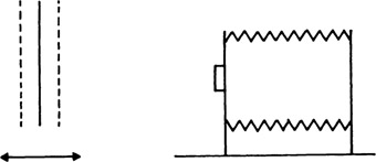
Figure 2-6
Focusing on a near object by moving the object.
2.3 Focusing and Depth of Field
Three-dimensional subjects and scenes force the photographer to make a decision concerning which part of the subject or scene to focus on. When a shallow depth of field is appropriate, the area of greatest interest is usually selected. With studio portraits, for example, the photographer normally focuses on the subject’s eyes and allows the ears and near and far shoulders to appear unsharp. When overall sharpness is desired, however, the camera must be focused on the appropriate distance so that as the lens is stopped down, the increased depth of field will reach both the near and the far parts of the subject.
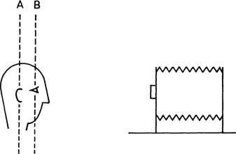
Figure 2-7
Plane of sharpest focus with soft-focus lens at the maximum aperture (B) and stopped down (A).
A commonly quoted rule of thumb states that when a large depth of field is desired, the camera should be focused one-third of the way into the part of the scene that is to appear sharp. Therefore, if the depth of field is to extend from 5 ft to 20 ft, the camera would be focused on 5 ft plus one-third of 15 ft, or a total distance of 10 ft. Unfortunately, this rule of thumb applies only to a limited number of situations. When the depth of field is small, as it tends to be with a long focal length lens, a large lens aperture, or a small object distance, the camera should be focused closer to midway between the near and far parts desired to be sharp. As the depth of field increases, the point focused on must move toward the front of the subject or scene (Figure 2-8).
When it is desired for the depth of field to extend back to infinity, or in measurable units even a mile or so, the camera should be focused on a distance that is identified as the hyperfocal distance. When the camera is focused on the hyperfocal distance, the depth of field extends from one-half of the hyperfocal distance to infinity. It should be noted that in this situation the camera is focused very close to the front of the depth-of-field range, not one-third of the way into it. Since the hyperfocal distance changes not only with lens focal length but also with the f-number used to expose the film, the easiest way to determine the hyperfocal distance is to refer to a depth-of-field table for the lens being used and locate the closest distance the lens can be focused on where the depth of field extends to infinity for the f-number being used. View camera depth-of-field focusing scales and guides that enable the photographer to easily determine both the depth of field and the optimum focusing distance are covered in Chapter 7.
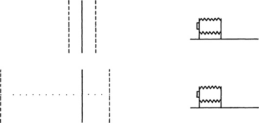
Figure 2-8
Distribution of depth of field in front of and behind the plane focused on with a shallow depth of field (top) and with a moderate depth of field (bottom).
Control over depth of field by the photographer can be summarized by noting the effect that a change in each of the three major variables—f-number, object distance, and lens focal length— has on depth of field. (1) Depth of field is proportional to the f-number, so that doubling the f-number from f/8 to f/16, for example, doubles the depth of field. (2) Depth of field is proportional to the object distance squared, so that doubling the object distance from 8 ft to 16 ft, for example, increases the depth of field by a factor of 2 squared, or 4. (3) The depth of field varies inversely with the focal length squared, so that substituting a 100-mm focal length lens for a 200-mm lens increases the depth of field by a factor of 4, and the shorter 100-mm lens produces a smaller image than the 200-mm lens. If the camera is also moved closer to produce the same image size of the object focused on, the decrease in the depth of field produced by reducing the object distance will offset the increase in depth of field produced by using the shorter focal length lens, and the two photographs will have essentially the same depth of field.
2.4 Tilts and Swings
When the front and back tilt and swing adjustments are in their normal or zero positions—that is, the lens board and ground glass are perpendicular to the monorail—they are in the same positions as the corresponding parts on cameras that have no tilt and swing adjustments. (All view cameras have a mechanical and/or visual indicator of the zero positions.) Many photographs are made with view cameras with the front and back in their zero positions, including typical studio portraits and landscapes. With some subjects having parallel vertical and horizontal subject lines that must remain parallel in the image, the view camera is simply set up directly in front of the subject and there is no convergence of the subject lines, as illustrated by the photograph of the test tubes and rack in Figure 2-9. The photograph of the building in Figure 2-10, in contrast, shows that tilting a camera upward causes the vertical subject lines to converge toward the top. Making photographic copies is another situation in which there is no need to use the tilt and swing adjustments, providing that the camera is placed in the correct position with the lens board and ground glass parallel to the original that is being copied. In situations where copies must be made frequently, special equipment is commonly used whereby the camera can be placed at varying distances from the original to accommodate different-size originals without having to be concerned about aligning the camera. A prime example of this is the process cameras used for making copies for photomechanical reproduction, where the camera and the copy board remain permanently aligned on rigid tracks. When a view camera is set up on a tripod to make an occasional copy, however, the task of aligning the camera and copy can be challenging. The task can be greatly simplified by placing a small mirror in the exact center of the original being copied, as illustrated in Figure 2-11. The camera will be correctly aligned when a reflection of the camera lens is located in the exact center of the ground glass. Grid lines on the ground glass are also helpful in making certain that there is no convergence of parallel subject lines in the image.
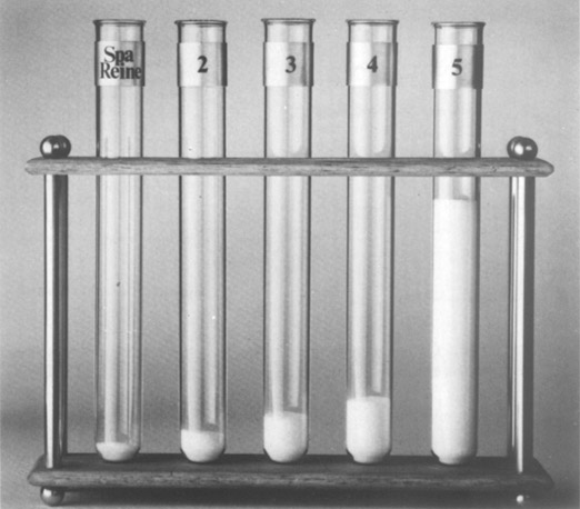
Figure 2-9
Parallel subject lines are imaged as parallel lines when the film plane is parallel to the subject lines.—Jean Paul Debattice
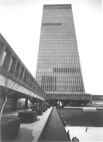
Figure 2-10
Tilting a camera upward causes vertical subject lines to converge toward the top of the image.
2.5 Controlling Image Shape
The effect of tilting and swinging the back of a view camera can be demonstrated by placing the camera in the copying position in front of a grid and examining the inverted image on the ground glass (1) with the back tilt and back swing both zeroed, (2) with the back tilted and the swing zeroed, and (3) with the back swung and the tilt zeroed, as illustrated in Figure 2-12. One can see that tilting the top of the back forward causes the vertical lines to converge toward the top of the ground glass, but the horizontal lines remain parallel. Also, swinging the left side of the back forward causes the horizontal lines to converge toward the left side of the ground glass, but the vertical lines remain parallel. The final photograph shows that substituting a longer focal length lens and moving the camera farther away from the subject, to obtain the same image size, results in less convergence of the horizontal lines even though the back is swung at the same angle as in the preceding photograph.
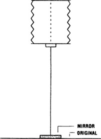
Figure 2-11
A mirror can be used to check camera alignment when making photographic copies.
The effects of tilting the back in both directions with respect to the final photograph, rather than the inverted ground-glass image, are shown in Figure 2-13. Tilting the top of the back away from the subject causes the vertical lines to converge toward the top of the photograph. (The reason the distance between the piles of blocks is smaller at the top than at the bottom is because the rays of light from the top travel a shorter distance between the lens and the film than the rays from the bottom.) It may be noted that the effect is very similar to that produced with a conventional camera when it is tilted up from street level to photograph a tall building, where the angle of the back in relation to the building would be the same as in this illustration. Tilting the back in the opposite direction, the top
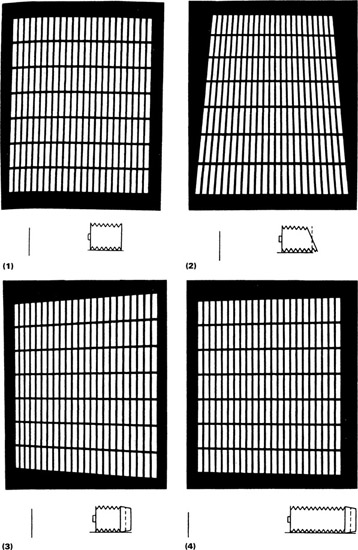
Figure 2-12
Inverted ground-glass images of a grid (1) with the camera back parallel to the grid, (2) with the top of the back tilted forward, (3) with the left side of the back swung forward, and (4) with the back swung at the same angle as in the preceding photograph but with a longer focal length lens and greater object distance.
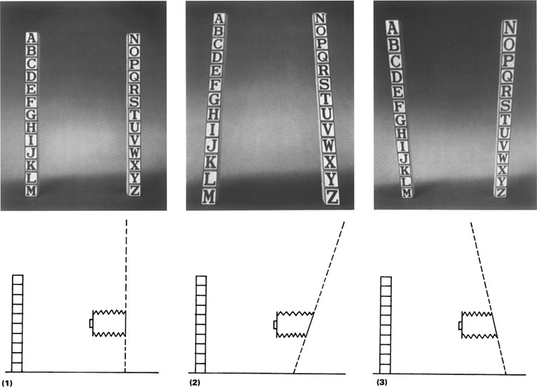
Figure 2-13
Photographs made with the camera level and (1) the back parallel to the subject, (2) the top of the back tilted away from the subject, and (3) the top of the back tilted toward the subject.
of the ground glass toward the subject, reversed the direction of convergence on the photograph, so that the convergence toward the bottom of the photograph is similar to the effect produced with a conventional camera tilted down at the subject from an elevated position.
The camera is moved to an elevated position and tilted down toward the subject for the three photographs in Figure 2-14. With the back in the zero position in the first photograph, the vertical subject lines converge toward the bottom. Tilting the back so that it is parallel to the subject lines and perpendicular to the ground eliminates the convergence in the second photograph. For the third photograph, the back is tilted in the opposite direction, that is, the top of the back is tilted toward rather than away from the subject, and the effect is to exaggerate the convergence over that produced in the first photograph with the back in the zero position.
It can be concluded that convergence of vertical subject lines in photographs depends on the relationship between the tilt angle of the camera back and the vertical subject lines, regardless of the height of the camera.
There are no rigid rules concerning whether vertical subject lines should or should not be allowed to converge in photographs made with the camera tilted up or down at the subject, but a tradition of rendering vertical subject lines parallel has long existed among photographers and artists for certain types of subjects and target audiences. Just as different words and phrases commonly are used to express the same thought in informal spoken language and formal written communication, different photographic styles are appropriate in different contexts. In any event, keeping vertical subject lines parallel represents the more formal approach that is commonly taken by photographers using view cameras, especially for architectural, commercial, and catalog-type photographs. The tradition is strong enough that perspective control (PC) lenses have been designed and marketed so that similar effects can be achieved with 35-mm cameras.
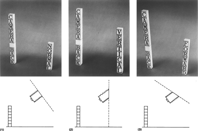
Figure 2-14
With the camera tilted down from an elevated position, the vertical subject lines (1) converge toward the bottom with the back in the normal position, (2) remain parallel when the back is tilted so that it is parallel to the subject, and (3) converge more strongly than in the first photograph when the back is tilted in the opposite direction.
The same relationship exists between subject plane and film plane for horizontal lines as just discussed for vertical lines; that is, the only time parallel horizontal lines will remain parallel in photographs is when the camera back is parallel to that subject plane. Fortunately, viewers are not as concerned about converging horizontal lines as they are about converging vertical lines, although in some situations it is desirable to either reduce or exaggerate the rate of convergence or even to entirely eliminate convergence. Altering the convergence of horizontal lines on the front of a low, long building, for example, tends to change the apparent length of the building in the photograph.
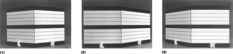
Figure 2-15
Three photographs taken from the same position (1) with the camera back in the normal position showing convergence of the horizontal lines on both subject planes, (2) with the back swung parallel to the left subject plane, and (3) with the back swung parallel to the right subject plane.
When two sides of a building or other box-shaped object are visible from the camera position, it is not possible (or desirable) to eliminate convergence of the horizontal lines on both sides simultaneously. The first photograph in Figure 2-15 shows that, with the swing back in the zero position, the parallel horizontal lines on the left and right sides of the box-shaped object converge toward vanishing points on the left and right sides, respectively. The second photograph shows that swinging the back parallel to the left side of the object eliminates convergence of the parallel subject lines on that surface but exaggerates convergence on the right side. Swinging the back parallel to the right side of the object reverses the results, eliminating convergence on the right side and exaggerating convergence on the left side, as shown in the third photograph.
One can see that the view camera offers considerable control over the convergence of both vertical and horizontal parallel lines. Slightly converging lines close to the edges of a photograph tend to be more disturbing to viewers than lines that converge more strongly, possibly because they create the impression that the convergence is due to carelessness rather than intent. With such vertical lines, there should be no hesitancy in tilting the back to eliminate the convergence. Horizontal lines on two sides of box-shaped objects allow for more flexibility of treatment. When one surface is obviously more important than the other, such as the front of a building or commercial product, or has already been given preference through choice of the camera viewpoint, eliminating convergence of the parallel subject lines on that surface will tend to be more suitable.
It is possible to increase or decrease the convergence of horizontal lines simultaneously on two planes that are at right angles to each other, but this must be done by changing the distance from the camera to the subject, usually accompanied by a change in lens focal length, rather than by swinging the back of the camera. This approach was illustrated in Figure 2-12 and will be discussed under the heading Simultaneous Changes in Object Distance and Focal Length in Chapter 6.
Professional photographers make decisions concerning eliminating, reducing, or exaggerating convergence of parallel vertical and horizontal subject lines on the basis of what appears to be appropriate for each subject and the intended use for the photograph, rather than by following rigid rules. When in doubt, however, it is usually safe to keep vertical subject lines parallel and allow horizontal lines to converge normally in the photograph.
The nine photographs in Figure 2-16 show the results of placing the tilt back in three different positions and the swing back in three different positions with the camera tilted down from an elevated position to photograph a vertical book that is rotated slightly sideways, as indicated by the top-view and side-view diagrams under the photographs. With the back tilt and swing adjustments zeroed, there is normal convergence (as occurs in the retinal image in our eyes) of both vertical and horizontal subject lines, as shown in the fifth photograph. Tilting the back parallel to the vertical book lines and swinging the back parallel to the horizontal book lines eliminate convergence in both sets of lines, as shown in the first photograph.
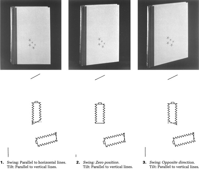
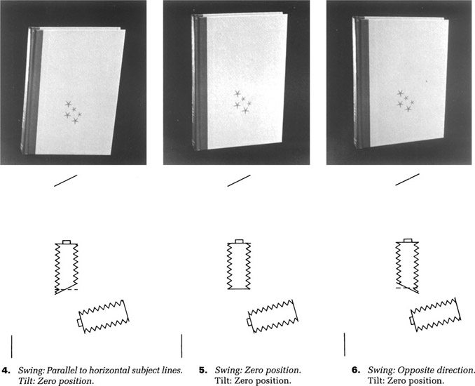
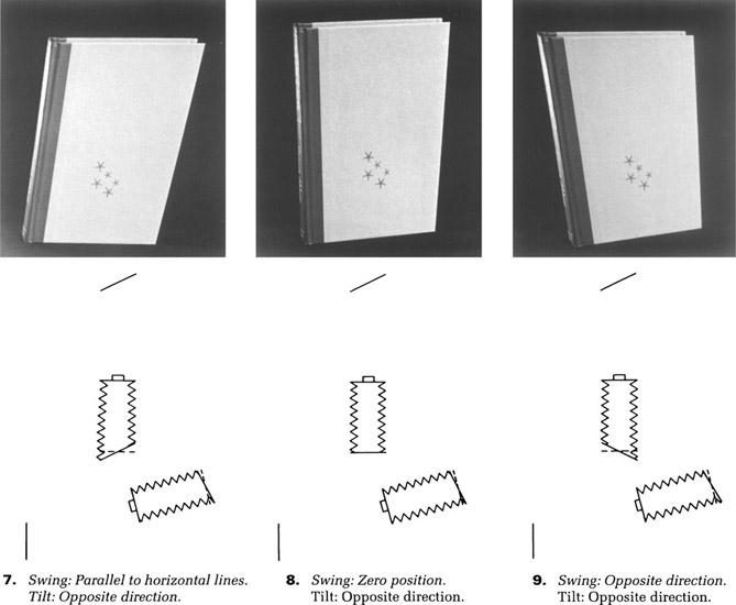
Figure 2-16
The nine photographs on this and the following two pages show the variety of image shapes that can be obtained with the camera back in three different tilt positions and three different swing positions (zero position, tilted or swung parallel to the subject plane, and tilted or swung in the opposite direction). The cameras under the photographs represent a top view for the back swing and a side view for the back tilt. The italicized words in the numbered captions indicate the swing and/or tilt adjustments that were changed from the previous illustration.
Progressing from the first photograph to the ninth, only one change is made in either the back tilt adjustment or the back swing adjustment between photographs, except for the fourth and seventh photographs, where both are changed. To assist the reader in making the association between the change in the position of the camera back and the change in the image shape, the changed camera-back positions are italicized in the captions. The same rules of thumb discussed previously of course still apply. Parallel subject lines will converge in the photograph when the camera back is not parallel to those subject lines. Convergence is eliminated by tilting or swinging the back so that it is parallel to the parallel subject lines, and convergence is exaggerated by tilting or swinging the back in the opposite direction. Exaggeration of both vertical and horizontal book lines is illustrated in the ninth photograph, for comparison with normal convergence of both in the fifth photograph and elimination of convergence of both in the first photograph.
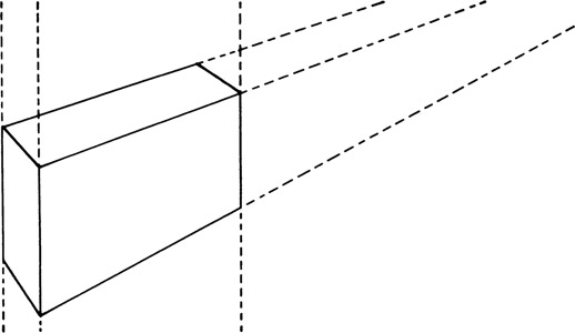
Although we have been concerned only with subjects containing parallel lines, the images of irregularly shaped objects are similarly affected by changes in the tilt and swing angles of the camera back (Figure 2-17). Casual viewers of photographs rarely notice such changes in image shape when the subject contains no straight lines unless the changes are dramatic, but critical viewers will detect more subtle changes.
In the preceding discussion on controlling image shape, all adjustments were made by tilting and swinging the back of the camera. To demonstrate that tilting (or swinging) the lens does not alter image shape, a view camera was set up in front of a grid having parallel vertical and horizontal lines with the lens board and back parallel to the grid, and one can see that the image has the same shape as the subject (Figure 2-18). Tilting the lens reduces the sharpness of the top and bottom of the image but does not affect its shape, although the variation in sharpness may create an illusion that the lines converge or perhaps are even curved (Figure 2-19). When the lens is stopped down to a smaller opening, however, the depth of field increases enough to reduce the loss of sharpness, and one can see that the image matches the first photograph made with the lens in the normal position (Figure 2-20).
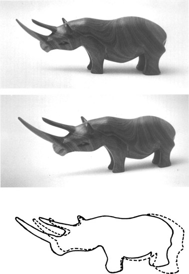
Figure 2-17
The change in shape of the image of an object having an irregular shape as a result of swinging the camera back in opposite directions. The dashed outline represents the top photograph, the solid outline the bottom photograph.
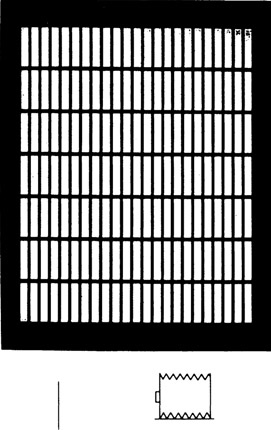
Figure 2-18
There is no convergence of vertical or horizontal subject lines on the ground-glass image when the lens board and camera back are both parallel to the subject. Images are inverted, as seen on the ground glass.
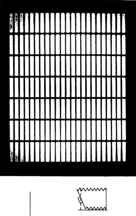
Figure 2-19
Image sharpness is affected, but not image shape, when the lens is tilted.
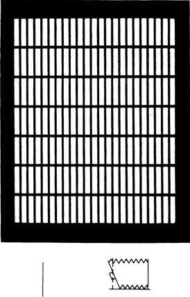
Figure 2-20
Use of a small aperture to obtain a sharp image reveals that tilting the lens has not altered image shape.
2.6 Controlling the Plane of Sharp Focus
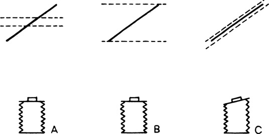
Figure 2-21
(A) With a shallow depth of field, represented by the dashed lines, only the center part of the subject will appear sharp. (B) Stopping the lens down increases the depth of field. (C) Swinging the lens changes the angle of the plane of sharp focus to produce a sharp image without stopping the lens down.
If a conventional camera (or a view camera with the front and back in the zero tilt and swing positions) is focused on the center of a flat object surface that is at an angle to the camera, with the lens diaphragm fully open, the closer and more distant parts of that surface will become progressively less sharp in the image (Figure 2-21A). Stopping the lens diaphragm down will increase the depth of field, as shown in Figure 2-21B, although in some situations it will be impossible to increase the depth of field sufficiently with this control to include the closest and most distant parts of the subject. With view cameras, however, the angle of the plane of sharp focus in object space can be changed to conform to the subject plane by adjusting the angle of the front of the camera, as shown in Figure 2-21C, making it unnecessary to stop the lens down to obtain a sharp image, regardless of the length of the subject.
In addition to changing image shape, tilting and swinging the camera back also alters the angle of the plane of sharp focus, a fact that we have ignored in the discussion of image shape. Although the back tilt and swing can be used to control the angle of the plane of sharp focus, that task is usually assigned to the front tilt and swing adjustments so that the back adjustments can be reserved for controlling image shape. When both front and back adjustments are used to control both image shape and the angle of the plane of sharp focus, it is important to adjust the back first—because the back affects both image shape and sharpness whereas the front affects only image sharpness. This advice can be summarized in three general rules:
- To control image shape when sharpness is not a factor, swing or tilt the back.
- To control image sharpness when shape is not a factor, swing or tilt the front and/or the back.
- To control both image shape and sharpness, swing or tilt the back first for shape, then swing or tilt the front for sharpness.
With the camera back in the zero position, the effect of swinging the camera front on the angle of the plane of sharp focus is as shown in Figure 2-22. It is often possible for the photographer to determine the correct angle of tilt or swing for sharpness control by examining the image on the ground glass as the adjustment is being made. This trial-and-error method can be time-consuming, especially when the subject lacks bold detail or when the image is dim due to a low light level. Adjustment of the camera front (or back) can be made more accurately and more rapidly by noting that optimum sharpness is obtained when the planes of the subject, camera front, and camera back are either parallel or meet at a common line, which appears as a point in two-dimensional drawings. The requirement that all three planes intersect at a line to obtain optimum image sharpness with angled subject planes is known as the Scheimpflug rule. (Theodor Scheimpflug was an Austrian army captain who
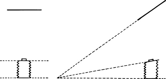
Figure 2-22
The subject, lens board, and film planes must either be parallel to each other or meet at a common line, as specified by the Scheimpflug rule, to obtain a sharp image at a large aperture.
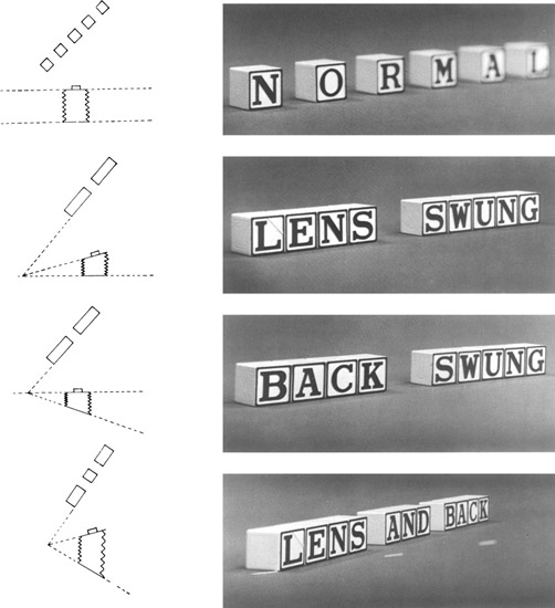
Figure 2-23
(Top) Only the near part of the subject appears sharp at a large aperture with the front and back swings zeroed. (Upper middle) A sharp image is obtained by swinging the lens toward the plane of the subject with the back in the zero position. (Lower middle) A sharp image is obtained by swinging the back in the opposite direction with the front in the zero position. (Bottom) Both the front and back swings can be used when the subject is at an extreme angle. The dashed white line in the photograph represents the maximum subject angle that could be imaged sharply using either the lens swing or the back swing.
studied photogrammetry and was awarded a British patent for his discussion of the theory of the relationship of the three planes.)
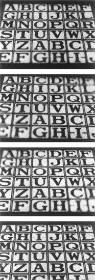
Figure 2-24
(Top) Only a narrow horizontal strip is sharp with all tilt and swing adjustments zeroed. (Upper and lower middle) Swinging the lens alters the angle at which the plane of sharp focus crosses the subject but does not help in achieving overall sharpness. (Bottom) Tilting the lens forward, with the swing zeroed, produces a sharp image of the entire subject.
The drawings and photographs in Figure 2-23 illustrate how a sharp image can be obtained of an angled subject plane by swinging the camera front only, the back only, or both the front and the back. Both adjustments are used when the subject is at such an extreme angle that neither the front nor the back provides enough control, due to either physical limitations on the swing or tilt adjustments or optical limitations involving the lens covering power. The first photograph, made with the camera front and back swing adjustments in their zero positions, shows loss of sharpness due to the limited depth of field with the lens diaphragm fully open. Sharp images are obtained by swinging only the front in the second photograph and by swinging only the back in the third photograph, with the lens diaphragm still wide open. The only difference between these two images is that the convergence of the horizontal subject lines was increased by swinging the camera back away from the angle of the subject, but since the subject has very little height, the change in convergence is not obvious. For the fourth photograph, the angle of the row of blocks was increased so that it became necessary to swing both the front and back to obtain a sharp image. The original angle of the blocks is indicated by the three dashes, two of which appear un-sharp.
Understanding the Scheimpflug rule helps the inexperienced view camera user in two basic ways. First, if the front is being used to control the angle of the plane of sharp focus, it is apparent that the front is rotated in the direction of the angle of the subject, and if the back is being used, that the back is rotated in the opposite direction. Second, the rule makes it possible to determine the correct angle of rotation of the camera front and/or back to obtain optimum image sharpness. It may be difficult for a photographer to determine whether the angle of rotation is correct while standing behind the camera, but by standing where extensions of the subject plane and the camera back plane meet, when using the front swing, one can easily see whether the angle of the camera front is correct, has been swung too far, or has not been swung far enough by looking down the three planes with one eye at the intersection point.
Inexperienced photographers sometimes become confused concerning whether to use a tilt or a swing adjustment to improve image sharpness in a given situation. With the camera tilted down to photograph a horizontal plane of letters with the front and back tilt and swing adjustments zeroed in Figure 2-24, the front and back rows of letters are not sharp when the camera is focused midway between them. When the front is swung rather than tilted, for the second and third photographs, the plane of sharp focus changes from a side-to-side direction to diagonal directions that vary with the direction in which the front was swung, leaving many of the letters un-sharp. Returning the front swing to the zero position and then tilting it to the correct angle produced overall sharpness in the fourth photograph. An application of tilting the camera front to improve image sharpness is shown in Figure 2-25.
Variations in the bellows extension affect the angle of the plane of sharp focus in addition to the angle of convergence of parallel lines, which was discussed previously. The angle at which the subject can be inclined with respect to the camera and yet be rendered sharp becomes less as the bellows extension increases. Thus, long focal length lenses and close objects, both of which require increased bellows extensions, limit the control that can be exercised over the plane of sharp focus. Observe the differences in the angles of the planes of sharp focus in the drawings in Figures 2-26 and 2-27, representing different focal length lenses, and three different object distances, with the angle of the back remaining constant.
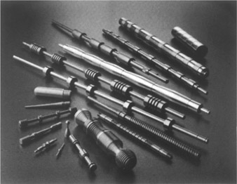
Figure 2-25
Overall image sharpness was obtained by tilting the top of the lens board forward.—Len Rosenberg
There are alternatives to using the Scheimpflug rule and the trial-and-error method while examining the image on the ground glass to determine the optimum angle of tilt or swing to obtain the desired angle of the plane of sharp focus in object space. The Sinar f1 and f2 cameras, for example, have a special angle scale dial that is designed to be used for this purpose (Figure 2-28A). To obtain sharp focus on an inclined subject plane, for example, the image is first focused on the bottom horizontal focusing line on the ground glass, the angle scale dial is set to 0, and the image is then focused on the top horizontal focusing line. A pointer indicates the correct tilt angle on the angle scale dial. The tilt angle can be applied to either the lens standard or the film standard. The procedure is even simpler with other Sinar view cameras with asymmetric tilting backs that rotate about an axis that coincides with the bottom horizontal focusing line on the ground glass (Figure 2-28B). The image is first focused on that line and then the back is tilted until the image also comes into focus on the top focus line. The photographer has the option of exposing the film with the back in that position or transferring the tilt angle to the lens standard and returning the back standard to the original setting.
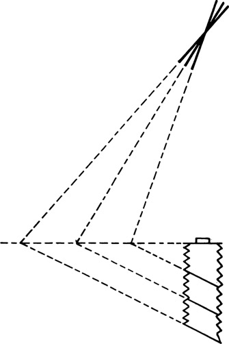
Figure 2-26
Relationship between lens focal length and angle of the plane of sharp focus.
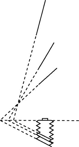
Figure 2-27
Relationship between object distance and the plane of sharp focus.
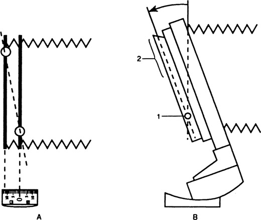
Figure 2-28
(A) Sinar f1 and f2 cameras are equipped with an angle scale dial that indicates the angle of tilt of the back or the lens board required to obtain sharp focus on an oblique subject plane. (B) With models having the asymmetrical tilt and swing back, overall sharpness is obtained by focusing the image of the oblique subject plane on the tilt-axis line near the bottom of the ground glass, then tilting the back until the image is in focus at the top.
With view cameras that have an electronic computer, either as an integral part of the camera or as an accessory, and the appropriate computer software program, the optimum tilt or swing angle is determined by the computer after data are captured by the computer for two or more object points.
Since altering the angle of the camera back affects both image shape and image sharpness, its use to control shape may either complicate or simplify the subsequent step of controlling sharpness with the camera front. Tilting a camera downward with the tilts and swings zeroed, for example, causes the vertical subject lines to converge and the plane of sharp focus to be at a different angle from the vertical plane of the subject, as shown in the first photograph in Figure 2-29, resulting in a loss of sharpness in the parts of the subject that deviate from the plane of sharp focus. Tilting the back to eliminate convergence of the vertical lines causes the plane of sharp focus to intersect the vertical subject at a more extreme angle, producing even greater loss of sharpness at the top and bottom of the subject, as shown in the second photograph. To obtain agreement between the plane of sharp focus and the subject, it becomes necessary to tilt the front to the vertical position so that the subject, the camera front, and the camera back are all parallel, as shown in the third photograph. If, on the other hand, the photographer wanted to exaggerate the convergence of the vertical subject lines from the same camera position, the back would be tilted in the opposite direction, which also would bring the plane of sharp focus into closer agreement with the subject, as shown in Figure 2-30. There is no assurance, however, that the back would be tilted to the exact angle required for optimum sharpness, so that it still might be necessary to tilt the front to obtain a sharp image without stopping the lens diaphragm down.
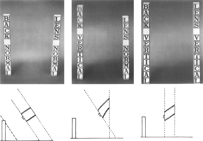
Figure 2-29
(Left) Appearance of the image with the camera tilted downward and with the tilt adjustments zeroed. (Center) Tilting the back to eliminate convergence of;the vertical lines also reduces the area of sharpness. (Right) Tilting the lens board so that it is parallel to the subject and the film plane produces a sharp image at the maximum diaphragm opening.
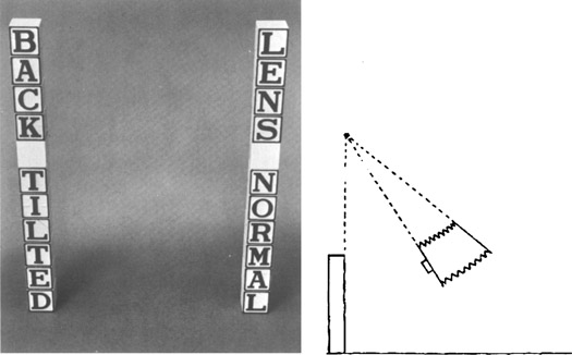
Figure 2-30
Tilting the back forward to exaggerate convergence will also produce a sharp image if the three planes meet at a common line.
2.7 Simultaneous Use of Tilts and Swings
In practice, it is not uncommon for photographers to encounter situations that require the use of tilts and swings to control image shape and sharpness on vertical and horizontal planes simultaneously. In the first photograph in Figure 2-31, for example, the camera is tilted both down and sideways at the subject, resulting (with the adjustments zeroed) in convergence of the vertical and horizontal lines and, when focused on the nearest corner, a progressive decrease in sharpness to the right and downward. In the second photograph, the back has been tilted to eliminate convergence of the vertical lines, which also produced a greater loss of sharpness from top to bottom, and the front has been swung to improve image sharpness from left to right. In the third photograph, the front has been tilted to improve the sharpness from top to bottom. The horizontal subject lines were allowed to converge normally.
2.8 Vertical and Horizontal Shifts
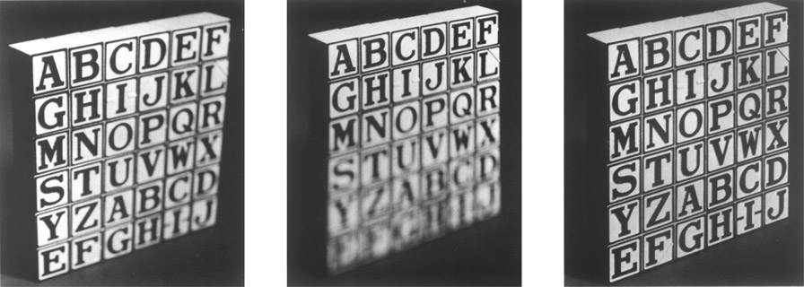
Figure 2-31
(Left) Appearance of the image with the tilt and swing adjustments zeroed. (Center) Effects of tilting the back to eliminate convergence of the vertical lines and swinging the lens to improve sharpness from left to right. (Right) Top-to-bottom sharpness obtained by tilting the lens.
The vertical shift (or rising-falling movement) and the horizontal (or lateral) shift alter the position of the image on the ground glass and the film without affecting image shape or the angle of the plane of sharp focus. Thus, if a view camera has been set up to photograph an object and the swings and tilts adjusted to obtain the desired image shape and angle for the plane of sharp focus, but the image is not centered as desired on the ground glass, it would be better to center the image by shifting the front or back than to position the image by tilting, swinging, or moving the entire camera, which would require readjustment of the swings and tilts. When copying a painting, for example, the camera would normally be set up with the front and back parallel to the painting so that there would be no convergence of the vertical and horizontal edges of the painting, and the plane of sharp focus would conform to the plane of the painting. The vertical shift moves the image up and down and the horizontal shift moves the image from side to side, and in both situations, the image moves approximately the same distance as the lens.
Shifting the lens moves the image in the same direction on the ground glass. Since the image is inverted on the ground glass, shifting the lens upward also moves the image upward on the ground glass, but in terms of the final photograph, the image moves down, as shown in Figure 2-32. Similarly, shifting the lens to the left moves the image to the left on the ground glass but to the right on the photograph. The opposite effect occurs, however, when the back is shifted. That is, shifting the back downward moves the image upward on the ground glass but downward on the photograph, and shifting the back to the right moves the image to the left on the ground glass but to the right on the photograph. The second photograph in Figure 2-32, therefore, could have been made by either shifting the front upward and to the left or shifting the back downward and to the right.
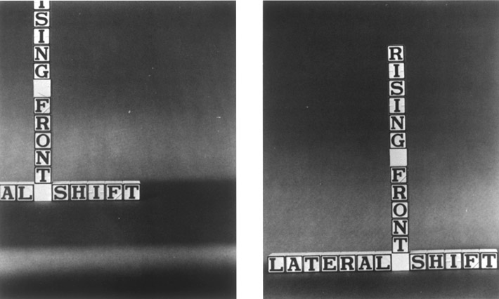
Figure 2-32
The front vertical and horizontal shift adjustments move the (inverted) image in the same vertical and horizontal directions on the ground glass, but in the opposite directions in terms of the erect print image.
Since shifting the front and back of the camera in opposite directions produces the same image movement on the ground glass, it can be concluded that, when mechanical limitations on the shifts prevent the desired effect from being achieved using either the front shift or the back shift alone, both can be used to obtain greater movement of the image by shifting them in opposite directions. When photographing a tall building, for example, if shifting the lens upward with the camera level does not move the image upward far enough to include the top of the building on the ground glass, the back then could be shifted downward. If the combination of the two changes still does not include the top of the building, the entire camera can be tilted up, followed by tilting both the front and back to vertical positions, as shown in Figure 2-33. Although there are no differences in the final image between using the vertical shift to elevate the lens with the camera level or tilting the camera upward and then tilting the front and back to vertical positions if the displacements between the lens and the film are the same, the latter method requires three steps—tilting the camera, tilting the front, and tilting the back—rather than one.
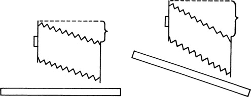
Figure 2-33
Lens displacement with front vertical shift (left) and increased displacement by tilting the bed up and using the front and back tilts (right).
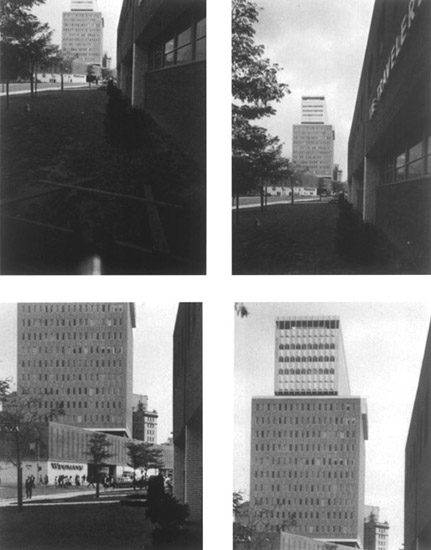
Figure 2-34
Raising the lens or lowering the back a distance of 2 in. will move the image of a distant object 2 in. on the film, regardless of the lens focal length.
Raising the lens a fixed distance, 2 in., for example, produces an equal displacement of the image on the film with distant objects (Figure 2-34). Lens focal length has no effect on the amount of displacement. With close objects, the displacement of the image on the film will be larger than the movement of the lens, and there will be some variation with focal length (Figure 2-35).
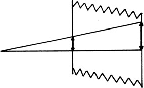
Figure 2-35
Rising front and image movement with a near object.
Another situation in which the vertical and horizontal shifts are useful occurs when a flat reflective surface, such as a mirror or a plate glass window, produces a reflection of the camera. For the first photograph in Figure 2-36, the mirror was placed on the floor to obtain a reflection of the white ceiling and the camera was placed directly over the mirror with all adjustments zeroed to obtain a rectangular image. To eliminate the reflection of the camera and tripod, the tripod was moved in the direction of the bottom of the mirror and then the front of the camera was shifted upward to reposition the image on the ground glass. If a reflection of the camera is seen on the glass covering framed artwork on a wall that is being copied, the camera could be either lowered, using the vertical shifts to reposition the image, or moved sideways, using the horizontal shifts to reposition the image. The shifts may also be useful in situations where an obstruction prevents the camera from being placed directly in front of a subject having parallel lines that are to appear parallel in the photograph.
2.9 Film Rotation
When it is necessary to switch between horizontal and vertical film formats with a handheld camera, the entire camera can be easily rotated. View cameras can be rotated in a similar way when using a pan-tilt tripod head that has both longitudinal and lateral tilt capabilities or when using a ball-joint tilt attachment. Also, some view cameras having tubular monorails can be rotated about the monorail by loosening the monorail clamp. Rotating the entire camera for this purpose has two disadvantages, however. Rotating changes the center of gravity of the camera in relation to the tripod, which may result in an unstable setup, and it changes the position of the lens in relation to the subject, which requires realignment of the camera when making closeup photographs.
View cameras have the capability of switching the ground glass and film holder between horizontal and vertical format positions without rotating the entire camera. With reversible backs, the back is detached from the camera, rotated, and reattached. With revolving backs, the back can be rotated without detaching it. With 360° revolving backs, the film can be placed in intermediate positions in addition to vertical and horizontal (Figure 2-37). The more limited type of revolving back that cuts off the image in the corners of the ground glass at the intermediate angles of rotation is used mostly when the compactness of a smaller bellows is more important than the versatility. Because 360° revolving backs require appreciably larger bellows than reversible backs, they are seldom used on the larger sizes of view cameras. Several manufacturers of 8 × 10-in. and larger view cameras offer the revolving-back feature on accessory reducing backs for smaller film sizes but-not on the larger standard backs.
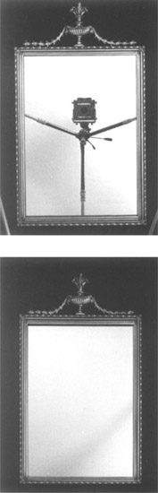
Figure 2-36
Elimination of a reflection in a mirror without altering its rectangular shape by moving the camera and tripod toward the bottom of the mirror and shifting the lens toward the top.
2.10 Effect of Back Movements on Image Shape
Alterations in perspective with changes in the angle of the film plane are essentially nothing more than changes in scale—from side to side when the back is swung, from top to bottom when the back is tilted, or diagonally when the back is both swung and tilted. Image size, for a given subject, depends on the relative distances from the subject to the lens (object distance) and from the lens to the film (image distance). A change in either distance results in a change in image size. Image size decreases as object distance increases, an inverse relationship. We are accustomed to seeing distant objects appear smaller than near objects, but we are more aware of the change in size when the near and far parts are connected with parallel lines, like railroad tracks or the edges of tall buildings.
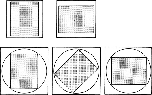
Figure 2-37
Reversible back (top) and 360° revolving back (bottom).
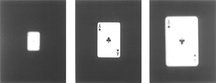
Figure 2-38
Increase in image size as lens-to-film distance increases.
Image size increases as image distance increases, a direct relationship. This relationship may not be obvious because the photographer is normally concentrating on obtaining sharp focus when adjusting the lens-to-film distance rather than observing the change in image size. However, it is easy to observe this change in image size even though the image goes considerably out of focus (Figure 2-38). The same change in image size with image distance can be observed with sharp images by using different focal length lenses.
Adjusting the back to compensate for differences in object distances of opposite ends of the subject requires an increase in image distance for the part of the image that appears too small with the back in the normal position. Since the light rays cross at the lens, the right side of the camera back is moved away from the lens when the left side of the subject is farther from the camera (Figure 2-39). The camera back and subject plane must be parallel to produce images of equal scale. With the back in this position, the ratio of image-to-object distances will be the same for all parts of the subject and the corresponding images. This relationship can be expressed as
Mathematical applications of this relationship are presented in Chapter 3.
The advantage of pivoting the back about axes that run through the center of the back for the tilt and swing adjustments is that this position minimizes any increase or decrease in image size in the center of the ground glass as the back is tilted or swung, which would require repositioning the camera to obtain the desired image size. With the centrally located pivot, the image size increases for the part of the back that moves away from the lens, remains unchanged at the point of pivot, and decreases for the part that moves toward the lens. This position of the pivot also minimizes the amount of refocusing required after adjustments have been made in the angle of the back or lens.
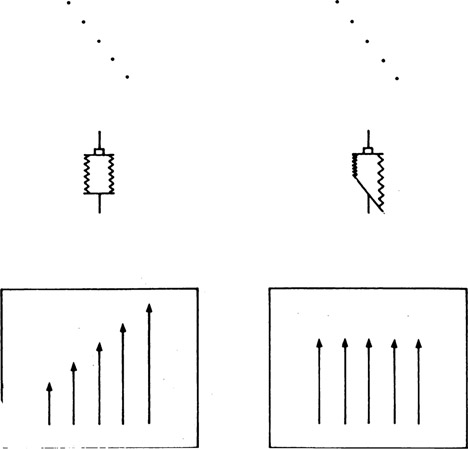
Figure 2-39
Back swung to compensate for difference in object distances of opposite ends of a subject.
2.11 Effect of Back Movements on Image Sharpness
Since the movements of the tilt and swing back are made in opposite directions to minimize convergence and to improve sharpness, the back cannot be used to control the plane of sharp focus except when there is no need to be concerned about perspective or, in the less frequent situation, when exaggeration rather than elimination of convergence is required.
An explanation of how the tilt and swing adjustments control the plane of sharp focus is simpler for the back than for the lens. Focusing on objects at varying distances from the camera reveals the fundamental relationship that, as the distance between the subject and the lens becomes smaller, the distance between the lens and the film must be increased to obtain a sharp image. This inverse relationship can be formulated as
Although specific mathematical applications of this formula will be deferred (see Chapter 3), we can observe that, with the focal length remaining constant, any change in object distance requires an inverse change in image distance. Figure 2-40 illustrates that, with a subject that is inclined with respect to the camera, the part of the subject closest to the camera comes to a focus farthest behind the lens, and Figure 2-41 shows that to obtain a sharp image the angle of the back is changed so that the points of sharpest focus all fall on the film. Because of the nature of the relationship, swinging or tilting the back to obtain optimum focus always places it in a position where the subject, lens, and back planes all meet at a common location (Figure 2-42).
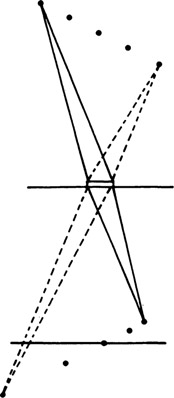
Figure 2-40
Near objects come to a focus farther behind the lens than distant objects.
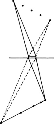
Figure 2-41
The back positioned to conform to the plane of sharp focus of the images.
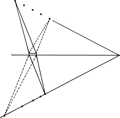
Figure 2-42
Subject, lens board, and image planes meet at a common location.
2.12 Effect of Lens Movements on Image Sharpness
The same inverse relationship between image and object distances can be used to explain control of the plane of sharp focus with the lens adjustment:
At first glance it appears that swinging or tilting the lens (about a point at the center of the lens) does not change the distances. Object and image distances are measured perpendicularly to a plane that is parallel to the lens board, however, rather than to the center of the lens. For now, we assume that the measurements are made to the plane of the lens board (Figure 2-43). Swinging the lens reduces the object distance for the most distant part of the subject, part A. A decrease in object distance results in an increase in image distance. The image of object point A now comes to a focus farther behind the lens board, and, when the lens is swung to the correct position, the sharp image falls on the film plane rather than in front of it. The converse occurs with the near part of the subject, and the ratio of image and object distances remains unchanged for the object point that was on the lens axis.
2.13 Types of Movement Limitations
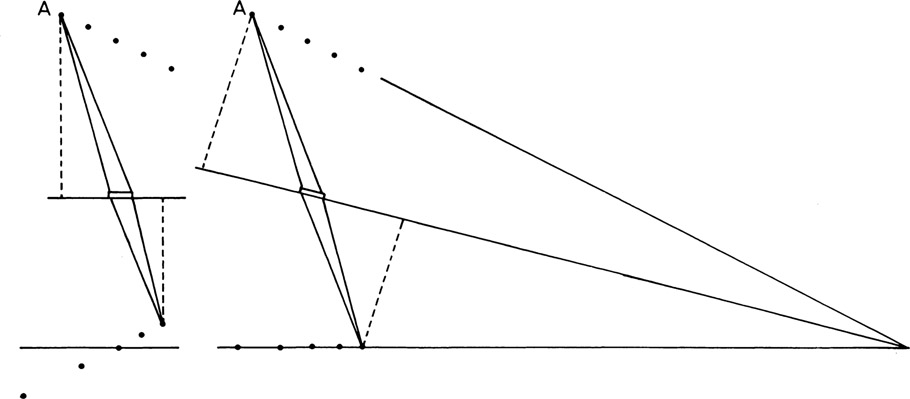
Figure 2-43
Effect of swinging the lens on object and image distances.
Three types of limitations are imposed on the acceptable amount of movement that can be made in the various camera adjustments—mechanical, optical, and aesthetic. Mechanical limitations to the maximum bellows extension and the extent of rise, shift, tilt, and swing movements are determined primarily by the design and construction of the camera. The mechanical limitations to some of the adjustments will not necessarily be the same for all lenses used on the camera, and it is not unusual for the mechanical movements of at least some of the adjustments to exceed the capabilities of the lens to form a satisfactory image. The optical limitations are then revealed as a loss of definition of a part or all of the image or as a variation in the illumination on the ground glass and film. Even though the photographer is not limited by mechanical or optical factors, the decision may be made to not fully correct converging lines or render an inclined subject entirely sharp for aesthetic reasons.
2.14 Focusing Limitations
Focusing limitations are mostly mechanical in nature. As the distance between the subject and the camera is decreased, a limit is reached where the distance between the lens and the film can no longer be increased to keep the image in sharp focus. The maximum bellows extension varies considerably among the various brands of view cameras. It should be noted that the maximum advertised extension can be obtained on some cameras only when all other adjustments are zeroed. One view camera that has a 17-in. bellows extension when all adjustments are in their normal positions is limited to 16 in. when the front is raised and 13 in. when the front is raised and the lens and back are tilted to their extreme positions. Modular-type view cameras generally provide for the addition of bed and bellows units, tandem style, to increase the maximum bellows extension.
Minimum bellows extension is not normally a problem with view cameras, but situations are encountered where the lens and film cannot be brought closely enough together to obtain a sharp image. This tends to occur when the camera is equipped with a short focal length lens and it is necessary to use the rising front, lateral shift, tilt, or swing adjustment, where the bellows may bind due to the limited space between the lens and back standards. Recessed lens boards minimize the difficulty by allowing the distance between the lens standard and the back standard to be increased while keeping the lens at the same distance from the film. Some view cameras have provisions for substituting special flexible, non-accordion-type bag bellows to minimize the binding (Figure 2-44).
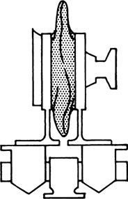
Figure 2-44
Bag bellows reduces restrictions on camera adjustments with short focal length lenses.
An optical limitation on the focusing may occur when photographing small objects from a close position with a large bellows extension. Under these conditions some lenses that have been designed for photographing objects at longer distances are not capable of producing images with satisfactory definition.
2.15 Lens Movement Limitations
All movements of the lens (rising-falling, lateral shift, tilt, and swing) change the relative position of the lens with respect to the film in such a way that the film is no longer centered in the part of the image field capable of producing the best definition. The extent to which the position of the lens may be altered before the definition or illumination of the image is seriously affected depends on the covering power of the lens. In the past, some press-type cameras were supplied with lenses of such limited covering power that the corners of the negative revealed noticeable loss of definition even with the lens in the normal position, and any use of the rising front resulted in an obvious loss of sharpness. At the other extreme, top-quality wide-angle lenses, especially in the longer focal lengths, have such excellent covering power that good definition is obtained over the entire negative area, even with extensive adjustments of the lenses on view cameras.
Mechanical limitations on lens movements vary considerably among the numerous makes of view cameras. The more flexible cameras appear as though they could almost photograph themselves when the adjustments are in the extreme positions. Limitations with such cameras are invariably due to optical and aesthetic factors rather than mechanical. Cameras with only modest movements of the lens can prove surprisingly versatile in the hands of a photographer who has a good understanding of view camera adjustments. For example, a limitation of ½ in. on the lateral shift might be expanded to an effective shift of 7 in. or more by shifting the back an equal distance in the opposite direction, swinging the lens and back, and changing the angle of the bed, as illustrated in Figure 2-45.
Viewers are quite tolerant of the treatment of image sharpness in photographs. They will accept photographs that are sharp overall, photographs that have a shallow depth of field, sometimes even photographs that have no sharp areas; and they will also accept photographs where the plane of sharp focus is at an extreme angle, provided each effect is appropriate for the subject. There is usually no problem where the subject consists of a single plane that can be rendered sharp by tilting or swinging the lens, but discretion must be used where adjusting the lens to improve the sharpness in one plane will decrease the sharpness in another plane or another part of the subject. For example, in photographing box-shaped objects, if two planes of equal size and importance are visible from the camera position, adjusting the plane of sharp focus to conform to one plane while sacrificing sharpness in the other may produce a disconcerting effect (Figure 2-46). Similarly, adjusting the plane of sharp focus to conform to the plane of the shoulders for a portrait may result in one sharp eye and one unsharp eye, a less attractive result than if the swing adjustment had not been used.
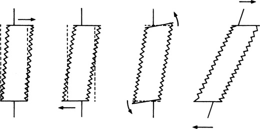
Figure 2-45
Use of swings to increase the lateral displacement of lens and back.
2.16 Back Movement Limitations
Mechanical limitations on the back movements are usually identical or similar to those on the lens. Not all view cameras have the same adjustments on the lens and the back, however. The rising-falling adjustment, which is used on both the lens and the back on a number of cameras, is omitted from the back on others. Tilt and swing adjustments were used on the back and not on the lens on some earlier view cameras (see Chapter 11), with the reverse situation of adjustments on the lens but not on the back on some later press-type cameras.
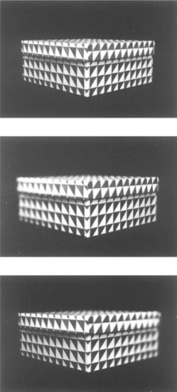
Figure 2-46
Adjusting the plane of sharp focus to conform to one plane of a box-shaped object while sacrificing the sharpness on the other plane tends to produce a disconcerting effect when the two planes are equal in importance.
Rising, falling, and lateral shift movements of the back produce essentially the same results obtained with those movements of the lens but in the opposite direction. That is, shifting the back ½ in. to the right is comparable to shifting the lens ½ in. to the left, and the optical limitations on the covering power of the lens are identical. Tilting and swinging the back, however, do not involve the same risk of having part of the film lie outside the covering power of the lens that is involved when the lens is tilted or swung. For this reason, it is safer to adjust the plane of sharp focus with the back than with the lens when using a lens having limited covering power, although the back adjustments must be reserved for perspective control when this is an important consideration.
Aesthetic limitations are imposed more on the swing and tilt adjustments of the back than on any of the other view camera movements. Although viewers apparently prefer to see parallel subject lines, especially vertical lines, rendered parallel on the print when the inclination of the camera is slight or moderate, the same treatment often produces an unnatural effect when the inclination of the camera is large. It is impossible to establish an absolute set of rules as to when parallel subject lines should be rendered parallel, when they should be allowed to converge, and the most acceptable angle of convergence. These things are concerned with the psychology of vision, and the interpretation of the image by the viewer depends on such factors as the shape and nature of the subject, the lighting, the viewer’s previous experience and training, and other factors. It is easy to deceive the eye into believing that two-dimensional objects are three-dimensional. Excellent examples of these and other effects appear in Ralph M. Evans’s Eye, Film, and Camera in Color Photography.2
It is important that the photographer does not create optical illusions, due to either carelessness or ignorance, when realism is the desired effect, although the possibilities of utilizing optical illusions, exaggerated realism, and other special effects when their use is appropriate should not be overlooked. The interpretation of converging lines on a print as normal perspective or as distorted perspective varies from person to person, although certain professional fields of photography have their own generally accepted conventions. Where realistic effects are required, vertical subject lines are almost always made parallel on the photograph, and parallel horizontal subject lines on receding planes are allowed to converge at a moderate rate. This treatment is illustrated by the drawing in Figure 2-47.
2.17 Anamorphic Effects
Even though the tilt and swing movements of the back of the view camera provide extensive control over the way parallel subject lines are recorded on the photograph, they may not always give the exact change of shape that the photographer requires. It may be desirable to make an object appear taller, longer, or shorter than in a straightforward photograph made without the use of special controls. A building, of course, can be made to appear taller by tilting the back of the camera away from the plane of the building so that the vertical lines converge more rapidly. If, however, the objective is to stretch the image and also keep the vertical subject lines parallel, the problem becomes more complex and the solution requires the use of printing controls or computer digital image–processing modification (see Chapter 12).
Tilting the easel can be used as a means of controlling the convergence of parallel subject lines at the printing stage, but it is more awkward and less satisfactory than tilting or swinging the back of the camera. Moreover, many enlargers lack a tilting lens adjustment to control the plane of sharp focus, and unexpected cropping difficulties may be encountered unless considerable space is provided around the desired area on the negative. True shape is obtained in the image when photographing a two-dimensional object by keeping the back of the camera parallel to the object. Therefore, tilting a camera upward to photograph a building produces an image with the same height-to-width proportions as on the building provided the back is positioned perpendicular to the ground to prevent convergence of the vertical lines. With the back in this position, there can be no stretching or compressing of the image. If, however, a negative is made under identical conditions except that the camera back is in the normal (zero) tilt position and the resulting converging vertical lines are made parallel by tilting the easel when the print is made, the height-to-width proportions of the image may be larger than, smaller than, or the same as on the subject.
Figure 2-48 illustrates the effects obtained by photographing a square two-dimensional subject from a low viewpoint. Whether true rectification is obtained or the image is stretched or compressed depends on the relationship between the bellows extension on the camera when the negative is exposed and the bellows extension on the enlarger when the print is exposed. When the two distances are equal, true rectification results. Stretching results when the enlarger bellows extension is larger, and compression results when it is smaller. Bellows extension on the camera is determined by the camera lens focal length and the distance from the subject to the camera, and the enlarger bellows extension is determined by the focal length of the enlarger lens and the distance from the enlarger lens to the easel.
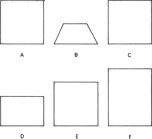
Figure 2-48
(A) A square two-dimensional subject. (B) Image produced with camera tilted upward and with back in zero position. (C) Image produced with back tilted parallel to subject. (D, E, F) Various effects obtainable by tilting the easel with a negative corresponding to image B.
The reason a change in either bellows extension affects the proportions of the image is that the angle to which the easel must be tilted to correct the converging lines depends on the ratio of the two bellows extensions. As the enlarger bellows extension increases, the required tilt of the easel and the stretching of the image will both increase (Figure 2-49). Thus, maximum stretching of the image will be obtained with a short focal length lens on the camera and a long focal length lens on the enlarger. (Also, more stretching will be obtained on a small print than on a large print.) A long focal length camera lens and a short focal length enlarger lens should be used to obtain maximum compression of the image. Difficulty may be encountered with poor definition at the edges of the print with enlarger lenses having a focal length shorter than the diagonal of the negative, due to their limited covering power.
When allowing lines to converge on the negative with the intention of correcting them by tilting the easel, precautions must be taken to avoid obtaining an image that cannot be cropped as desired on the final print. As the easel is tilted to make the converging lines on the negative parallel on the projected image, the edges of the negative (or the edges of the opening in the negative carrier), which are actually parallel, will diverge on the projected image. Unless sufficient space is provided around the desired image area on the negative, it may be impossible to include all the image on the print without also showing the edges of the negative at one end of the print, as illustrated in Figure 2-50.
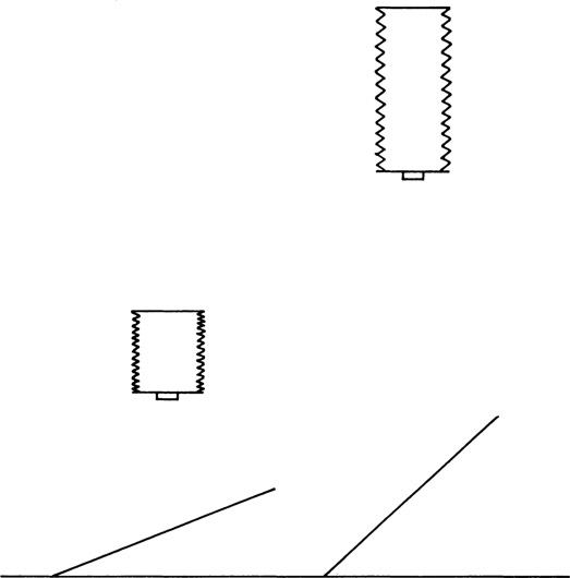
Figure 2-49
The longer enlarger bellows (right) requires a steeper tilt of easel, which results in elongation of the image.
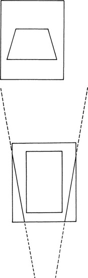
Figure 2-50
Negative with image containing converging lines (top). Projected image on a tilted easel [bottom). Converging lines on the negative are parallel on the easel, but edges of the negative converge and are included in the picture area.
Notes
1 P. Parga and R. Youso, SPSE News 7, no. 3 (May-June 1964).
2 Ralph M. Evans, Eye, Film, and Camera in Color Photography. New York: John Wiley and Sons, Inc.; London: Chapman and Hall, Limited, 1959.