Chapter 7
Immunity, Safety, Energy and Legislation
“Eyes are the windows of the soul”
George Rodenbach,
1855–1898
The emitted optical radiation of the emission module of an optical device is a very significant parameter in the calculation of the optical link budget. This radiation is characterized by the emitted power, its aperture (or field of view — FOV), and the emission wavelength. For reasons of safety, precautions or limitations can be considered according to the values of these three parameters. This is what will be developed in the first part of this chapter. The second part will approach the safety aspect of the communication, the third part evokes the power consumption, and, finally, the last part relates to the legislation.
7.1. Immunity
7.1.1. International references
Human beings, among others, can see wavelengths ranging from 400 nm (blue) to 700 nm (red), this is probably due to the evolution of the species, because this range corresponds to the peak of the solar spectrum (see Figure 3.12). Nevertheless, some tissues of the human eye can also interact with other ranges of the spectrum of optical radiation and are thus likely to be damaged under particular conditions.
In the near infrared (from 700 nm to 1,400 nm), radiations can be particularly dangerous for the retina of the eye (Figure 7.1), not only because of the process of concentration of the optical beam by the eye, but especially because of the absence of the palpebral reflex (blinking of the eyelid), for these non-visible radiations.
Figure 7.1. Schematic cross section of an eye

Beyond the near infrared (>1,400 nm), radiations are absorbed by the cornea of the eye and high optical powers can burn the cornea.
Under the visible light (<400 nm), i.e. in the field of the ultraviolet (UV), the effects of an excessive exposure on the skin are now well known (degeneration of cutaneous tissues or “photo-aging”). The acute exposure of the eye to UV can induce painful effects (conjunctivitis) which are reversible and it does not seem to create long-term lesions. Acute and chronic effects can appear as an appearance of a veil on the cornea or a cataract.
To eliminate any potential risk, there are international organizations which provide directives on safety for the transmission of a laser beam. Most significant is the International Electrotechnical Commission (IEC). IEC is an organization for standardization in the fields of electricity, electronics, and related techniques. The majority of its standards are developed jointly with the International Organization for Standardization (ISO). IEC is a standards’ organization dealing with areas of electricity, electronics, and related technologies. IEC was set up in 1906 and is currently based in Geneva. More than 60 countries are now members of IEC.
In the field of the radiation from a laser beam, IEC published several standards, the principal ones in connection with telecommunications are:
– IEC 60825-1 (2008): Safety of laser products — Part 1: equipment classification and requirements;
– IEC 60825-2 (2008): Safety of laser products — Part 2: safety of optical fiber communication systems (QFCS);
– IEC 60825-12 (2004): Safety of laser products — Part 12: safety of free-space optical communication systems used for transmission of information.
In the field of light-emitting diodes (LED) functioning in the visible spectra, the European Commission recommends Directive 2006/25/CE on the protection of workers against exposure to risks due to the artificial optical radiations. There are two well-known risks:
The adverse effects due to sparking: The variation of the radiation power of a visible light can induce an undesirable physiological reaction like headaches or a loss of concentration [KUL 98]. In extreme cases, it can cause epileptic fits in a minority of the population [HAR 94]. However, the frequencies of modulation for the majority of the wireless optical communication systems are higher than 500 kHz and are thus much higher than the highest limit of the cutoff frequencies for the adverse effects mentioned.
The temporary blindness: Because of the strong luminosity of some LEDs, it is possible to undergo a temporary blindness with an effect of retinal remanence [REI 09]. The blindness effect, caused by an overload of the retinal receivers, can persist up to 5 s; whereas the effect of retinal remanence can persist up to 20 s, even when the powerful light resulting from the LED is seen from several meters.
Standard IEC 60825-1 (last edition 2008) and its European integral version IN 60825-1 [EN608] are regarded as the reference for wireless optical devices of data transmission in confined space using a coherent beam.
For the measurement of a safety level of a laser source, this standard defines a parameter known as the maximum permissible exposure (MPE); it is the electromagnetic radiation level to which a human observer can be exposed during a certain time without incurring immediately or later, harmful effects.
The second parameter is the accessible emission limit (AEL). This value is derived from MPE and allows class definition of laser equipment. The classes categorize a level of risk or harmlessness. It is obligatory and references mention all apparatus containing a laser source.
7.1.2. Type of laser classes
The standard IN 60825-1 indexes lasers in seven classes, numbered from 1 to 4, and whose risk increases from class 1 to class 4 (Table 7.1). The limit of each class is based on the power or the energy values emitted by the laser sources and accessibility to the user.
Table 7.1. Classification of the lasers
| Class | Fields |
| 1 | A class 1 laser is safe under all conditions of normal use. This means that the MPE cannot be exceeded. |
| 1M | A class 1M laser is safe for all conditions of use except when passed through magnifying optics, such as microscopes and telescopes. Class 1M lasers produce large-diameter beams or divergent beams. The MPE cannot normally be exceeded unless focusing or imaging optics is used to narrow the beam. A laser can be classified as class 1M if the total output power is below class 3B but the power that can pass through the pupil of the eye is within class 1. |
| 2 | A class 2 laser is safe because the blink reflex will limit the exposure to no more than 0.25 s. It only applies to visible-light lasers (400–700 nm). Class 2 lasers are limited to 1 mW continuous wave, or more if the emission time is less than 0.25 s or if the light is not spatially coherent. Many laser pointers are class 2. |
| 2M | A class 2M laser is safe because of the blink reflex if not viewed through optical instruments. As with class 1M, this applies to laser beams with a large diameter or large divergence, for which the amount of light passing through the pupil cannot exceed the limits for class 2. |
| 3R | A class 3R laser is considered safe if handled carefully, with restricted beam viewing. With a class 3R laser, the MPE can be exceeded, but with a low risk of injury. Visible continuous lasers are limited to 5 mW. |
| 3B | A Class 3B laser is hazardous if the eye is exposed directly, but diffuse reflections such as from paper or other surfaces are not harmful. Continuous lasers in the range from 315 nm to far infrared are limited to 0.5 W. For pulsed lasers from 400 nm to 700 nm, the limit is 30 mW. Other limits apply to other wavelengths and to ultrashort lasers. |
| 4 | Class 4 lasers include all lasers with beam power greater than class 3B. By definition, a class 4 laser can burn the skin, or can cause potentially devastating and permanent eye damage as a result of direct or diffuse beam viewing. These lasers may ignite combustible materials, and thus may represent a fire risk. Some industrial, scientific, military, and medical lasers are in this category. |
According to the laser classification of the equipment, protection and safety devices are possibly implemented (cover of protection, operation with key, blocking of access, etc.). Complementary, the standard indicates the obligatory or optional informations to show on the equipment. This informations will be different according to the laser class and are indicated in Table 7.2.
Table 7.2. Legal mention of information
| Class | Fields |
| 1 | Each laser of class 1 must carry an explanatory label being marked “Laser class 1”. If not, to replace the label and with the discretion of the manufacturer, the same declarations can be included in the guide of information for the user. |
| 1M | Each laser of class 1M must carry an explanatory label being marked “Radiation laser. Not to look at directly with optical instruments. Laser class: 1M”. If not, to replace the label and with the discretion of the manufacturer, the same declarations can be included in the guide of information for the user. It is possible to add after “instruments” the mention “binocular or telescopes”. If the AEL exceeds the value of the class 3B, the mention “the exposure of the skin close to the opening can cause burns” must be added. |
| 2 | Each laser of class 2 must carry an explanatory label being marked “Radiation laser, not to look at the beam, laser. Laser class 2”. |
| 2M | Each laser of class 2M must carry an explanatory label being marked “Radiation laser, not to look at the beam or to see directly with optical instruments, laser. Laser class 2M”. It is possible to add after “instruments” the mention “binocular or telescopes”. If the AEL exceeds the value of the class 3B, the mention “the exposure of the skin close to the opening can cause burns” must be added. |
| 3R | Protective eyewear is typically required where direct viewing of a class 3B laser beam may occur. Each laser of class 3R must carry at least an explanatory label being marked “Radiation laser. Avoid the direct exposure of the eye, laser. Laser class 3R”. It is possible to replace the mention “Avoid the direct exposure of the eye” by “Avoid the exposure to the rays”. |
| 3B | Class 3B lasers must be equipped with a key switch and a safety interlock. Each laser of class 3B must carry at least an explanatory label being marked “Radiation laser. Avoid the exposure to the rays. Laser class 3B”. |
| 4 | Class 4 lasers must be equipped with a key switch and a safety interlock. Each laser of class 4 must carry at least an explanatory label being marked “Radiation laser. Avoid the exposure of the eyes or of the skin to the direct or diffuse radiation, Laser class 4”. |
In light of information coming from Tables 7.1 and 7.2, a wireless optical equipment of numerical data transmission for general public use must be of class 1. Indeed, a laser of class 1 is not dangerous even if the beam is visualized with an optical instrument such as a telescope or a magnifying glass.
Standard 60825-1 more precisely characterizes the apparatuses of class 1 in the following way (Appendix C of the standard): “laser apparatuses which are without danger during the use, including the visualization of the direct beam in the long run, even when the exposure occurs with instruments of optical visualization (magnifying glasses or binoculars). Class 1 also includes lasers of strong power which are entirely locked up so that no potentially dangerous radiation is accessible in the course of use (embarked laser products)”.
A remark is added for the beams emitted in the visible spectrum from a laser: “the visualization of the beam of a laser product of class 1, which emits in the visible one, can still produce dazzling visual effects, in particular with a weak ambient light”.
7.1.3. Method for calculation
The standard provides a table with which AEL can be calculated for class 1 according to various factors, such as the wavelength, the duration, and the size of the image on the retina of the eye. The size of the image on the retina is the surface of the optical beam which arrives at the retina after concentration of the beam. The result of this focusing on the retina will be different if the laser source is punctual (low size with a low divergence of the beam) or wide (strong divergence of the beam, e.g. a lamp) as shown in Figure 7.2.
Figure 7.2. Low size and wide sources

In addition, there are three conditions of measurement specifying the aperture diameter and the distance from the source in order to determine the laser class of this source.
Condition 1: intended for a collimated beam (parallel rays) where telescopes and binoculars can increase the danger;
Condition 2: intended for the divergent sources, where the use of magnifying glasses or microscopes can increase the danger;
Condition 3: apply to the naked eye.
In the standard, it is explicitly mentioned that the condition of the most restrictive measurement must always be applied, i.e. the power accessible from a laser of class 1, measured at the exit of the measurement aperture, should never exceed AEL from class 1 for these three conditions.
Moreover, two sets of evaluation are specified in correspondence with each of the three measurement conditions:
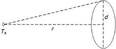
– A simplified evaluation presentation (by default) that covers all the point sources. The three conditions are associated with the measurement process for various values of distance r and aperture diameter d (Figure 7.3); the power emitted at the measurement aperture should not exceed AEL; the simplified evaluation can be applied to wide sources and that induces more restrictive limits.
– For the wide sources (e.g. a laser with an optical diffuser), a second more complex evaluation method can be applied, with less constraining emission limits. When this method is applied, a correction factor is included in the process of research of AEL value.
Figure 7.3. Configuration of measurement
Several factors of correction are introduced into the formula of power of accessible emission limit (PAEL). They depend on the wavelength, the diameter, the measurement aperture, and the duration.
Indeed, AEL at the output of the measurement aperture depends also on the duration. The standard prescribes a duration of 100 s for the class 1 products if the intentional vision in the long term is not inherent in the design or the function of the product. This duration must be taken into account in the range from 400 nm to 700 nm (visible range) but in infrared field (higher than 700 nm); the characteristics of calculation remain unchanged for durations higher than 100 s.
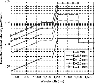
Figure 7.4 shows, in the form of graph, several results of the computing process in the field of infrared [WOL 08]. In this spectral range, the power of the PAEL is similar to the power of the maximum permissible exposure (PMPE). These results are presented in terms of maximum acceptable radiation intensity (source of emission in one solid angle unit) according to the wavelength, for various diameters (d) of the emission source. The curve d = 0 corresponds to a point source.
Figure 7.4. Allowed radiation intensity class 1 [WOL 08]
The results were calculated and presented with the most restrictive condition:
– for the punctual sources, condition 2 with the default method (d = 0);
– for the wide sources, condition 3 with the more complex evaluation method;
– for remind, the relation between the normal intensity radiated in the normal direction I(0) and the power is (equation [6.4]) given by:
![]()
And the steradian defines the solid angle. It is calculated as being the solid angle that, having its top in the center of a sphere, cuts, on the surface of this sphere, a surface, most often circular, equivalent to that of a square whose side is equal to the ray of the sphere. A steradian (Sr or srad) of solid angle corresponds to a plane angle whose top is approximately 60° or ±30°.
Consider the Cases 2 and 5 of Table 6.3 (Chapter 6). The power values are 20 dBm (100 mW) with an aperture angle of ±30° (m = 4.82) and ±15° (m = 20), respectively. The values of the normal intensity I(0) radiated in the normal direction will thus be 92.6 mW and 334.2 mW. If the proposed system functions with a wavelength of 850 nm and with an aperture diameter of 1 mm, the graph indicates us a maximum acceptable radiation intensity lower than 1,200 mW. Therefore, the two products, from Case 2 and 5, are indexed in class 1.
As well as the eye, the human skin is also sensitive to damage caused by optical radiations. The standard also specifies an MPE for the skin, which must be measured at the point where the exposure level is highest. This value also depends on the wavelength, the diameter of the aperture window, and the distance between the emission source and the directly accessible point. For example, in the most critical case, if the source is directly placed on the emission window with a beam diameter lower than 3.5 mm, the value of the maximum power MPE would be 100 mW.
The implementation of the emission devices of a wireless optical system requiring a minimal focal distance to make the beam divergent makes improbable this configuration.
Nevertheless, the emitted total power must be lower than 500 mW to be in conformity with class 1 for the requirements on skin safety [WOL 08].
7.2. The confidentiality of communication
The confidentiality of a communication between two interlocutors is assured if a third person or an unspecified detector cannot collect exchanged information. To ensure this safety, there are physical solutions by material techniques and numerical solutions by information coding, the last field is called cryptography.
7.2.1. Physical confidentiality
The fundamental element is that the light of the optical spectrum (ultraviolet, visible, and infrared) does not pass through walls. The optical transmissions are thus confined inside a room and they are consequently naturally better protected.
In spite of the existence of an aperture in a room, such as doors and windows, the visible signal becomes so attenuated and diverging that the possibilities to collect part of the beam become difficult. Hacking of information is more restricted than for the radiocommunications.
Moreover, the insertion of blinds or curtains window level brings a notoriously effective protection. Moreover, the existence of materials placed on windows, with different coefficients of transmission according to the wavelengths, can offer an additional safety [BOU 04]. Concerning the possibilities of propagation in a corridor or another part, the closing of a door offers, this, level of a simple and effective safety.
Finally, the non-deterministic wavelength jump solution presents one possibility of physical safety (related to a synchronization algorithm) of communication up to that point unequalled.
7.2.2. Numerical solution
The technique used is called the cryptography and several possibilities of cryptography are offered, from classic key cryptography to quantum cryptography [SCH 96, SIN 01]. Confidentiality of a communication between two communicators is assured if a third person or an unspecified detector cannot collect exchanged information. To do that, we can either code information, this is the domain of cryptography, or prohibit (by material techniques) beams of information to go to places where it is not wished.
7.2.2.1. Cryptography
The confidentiality of the communications can be of strategic importance as much for economic questions as for military ones; it is also the protection of privacy. To ensure confidentiality, the interlocutors must then return the contents of their messages, incomprehensible to a third person or more likely to one possible spy. The technique used is the cryptography, which literally is the art of to hide (crypto) a written text (graphy). Whatever the technique used in cryptography, the guiding principle is always the same. A transmitter, called traditionally Alice, codes her message using a key. The result is an encrypted message, which she sends to her correspondent called traditionally Bob.
This Person-Bob, using key deciphers receives the message and can read it. Confidentiality correspondence between Alice and Bob is guaranteed owing to the fact that a third person, who is also traditionally called Eve as a spy, does not have the deciphering key. It is permitted that the safety of an encryption system does not depend on the safeguarding of the secrecy of the algorithm, but only of the key secrecy.
Since the beginning of cryptography, we have seen an escalation in activity between cryptographs and code breakers. When the codes do not resist to Eve any more, Alice and Bob must change their cryptographic protocol. In addition, protocols must be increasingly complex so that it is necessary to change them as little as possible.
7.2.2.2. Public and secret key cryptography
In electronic communication, we are currently using RSA (Rivest, Shamir, Adleman) code which is a public-key code, thus avoiding the constraint that the two interlocutors must obligatorily first exchange the secret key. The safety of the algorithm rests on a mathematical conjecture, which stipulates that it is very difficult to calculate p and q prime numbers from their product. This conjecture was established from the mathematical properties of the best known factorization algorithms and the computing power of the computers. Nevertheless, it is not proved that the current factorization algorithms are optimal. As for the computers, power doubles, according to the Moore law, every 18 months. Increasingly large keys are factorized. Currently, we regard as sure those 1,024 bits keys at least. This key could be factorized in 2,048 bits, taking into account the known evolutions.
Based on unproven mathematical conjectures, although simple to implement since there is no exchange of secret key, RSA algorithm does not allow absolute communication safety. For safer exchanges, we can turn toward secret key codes. There is then no complex algorithm to use. But the key must be as long as the coded message and should be used only once. These conditions mean that this type of cryptography is used only at the diplomatic and military level.
Therefore, we have on the one side a public-key algorithm which does not require the exchange of a secret key but whose absolute safety is not guaranteed. And on the other side, we have an infallible proven algorithm, which requires the exchange of a secret key at the time of each mail.
7.2.2.3. Quantum cryptography
The only coding technique to guarantee the perfect inviolability of the communications, quantum cryptography rests on the exchange of single photons between the two correspondents. Quantum cryptography takes advantage of the Heisenberg uncertainty principle. Some characteristics of a quantum state cannot be measured simultaneously: whoever measures one modifies the others. The quantum state represents the key here allowing us to decode the message.
We can code a bit of information on the state of polarization of a single photon (qubit), but this information could be read only if we know the base of polarization in which it was coded.
The property of the quantum mechanics which will guarantee the safety of transmission of the key is the not-cloning theorem. It is not possible to copy an unknown quantum state perfectly: a spy cannot copy a qubit. We can thus distribute a coding quantum key (QKD — quantum key distribution), by coding information on the state of polarization of a single photon. When the key is as long as the message, the confidentiality is total, any mathematical attack is able to break it.
The luminous impulses are single photons, sent one-by-one, and Alice knows their state of polarization. To handle these single photons, it is necessary to have sources of single photons and detectors of such single photons.
7.2.2.4. Quantum telecommunications in free space
Quantum transmissions in free space were carried out, but more often starting from approximations of single photons sources.
From an attenuated coherent source: this method, generally applied to simulate a source of single photons, consists of strongly attenuating a photon beam from an impulse laser. For an average number of 0.1 photon by impulse, there are 90.5% of empty impulses, 9% contain a photon, and 0.5% contain two photons. These statistics of the number of variable photons according to the impulse are not very satisfactory for true communications although it is interesting for laboratory experiments.
The first experimentation in 1992 was made on a distance of 30 cm in free space [BEN 92]. The known record by the authors is an exchange of secret key in free space on a distance of 23 km in mountain environment [KUR 02]. The climatic fluctuations and parasitic lights are then the essential problems.
Single nitrogen-vacancy centers (called NV centers) in a diamond nanocrystal emit photons with a wavelength around 637 nm [BEV 02]; by dilution of these NV centers in the matrix, the authors carried out a single photons source. On a distance of 50 m in free space, approximately 8,000 secret bits per second were transmitted. This system allows a quantum key distribution “on request”, but not at wavelengths suitable for free-space telecommunications.
Another single photons source is proposed starting from erbium ions diluted in a matrix-host with large gap, a dielectric such as silica, for example, [DEF 01] and which the emission of the single photon at 1.55 μm emitted by only one exited erbium is collected in a near field by a thinned fiber before being re-emitted in free space. This technique allows us to have really a source of single photons at the traditional wavelength of optical telecommunications (1.55 μm) and at the ambient temperature. Due to the flexibility of optical fiber, here we have a very great simplicity of implementation that must facilitate the alignment problems between the transmitter and the detector. For optical links in free space requiring an absolute secrecy, this type of quantum keys exchange can prove absolutely useful.
7.2.2.5. Non-encrypted connections in confined space
The confidentiality guarantee of the non-encrypted communications in confined spaces imposes to limit the maximum transfer of information out of the limits of this space where the communications take place. In a meeting room, researchers [DEF 02] showed that the use of structured artificial materials can guarantee the confidentiality. Structured artificial materials with two or three dimensions would allow us to have perfect reflectors.
7.3. Energy
The search for communication systems with low power consumption is more and more sought after and this parameter now influences the behavior of the consumers. In this respect, the energy comparison is one increasingly significant and relevant aspect in the choice of a technology.
It is generally difficult to compare the energy consumption of various systems. The total consumed energy is constituted from the energy necessary to transmit the data as well as the power consumption for the signal and data processing. Table 7.3 presents an example of comparison and indicates that optical wireless communications can present a more economic energy/debit ratio. Because of this least power consumption and of its compactness, the wireless optical system is more and more used in the satellites [SOD 09].
Table 7.3. Energy comparison

Moreover, because of the characteristic of the transmission media, i.e. the use of an optical beam in visible or an infrared field, it is possible to re-use, in addition to daylight, the optical energy sent for the data communication.
For example, let us take a smart object in wireless optics with a consumption of 10 W which functions 10 h/day. The power consumption per day of this equipment is thus 100 Wh.
The electric production of a photovoltaic plate of dimension A4 (0.06 m2), without orientation or tilting optimization in a room, can reach approximately 20 Wh/day [ENE 11]. It is thus currently possible to obtain, with the example of consumption and in the current state of the photovoltaic output, more than 20% of free energy per day.
7.4. Legislation
7.4.1. Organization of regulation activities
International Telecommunication Union (ITU), whose headquarter is in Geneva (Switzerland), is an international organization under the United Nations system within which States and private companies coordinate global telecommunications services and networks. The ITU is structured in three distinct sectors:
– ITU-D: Development;
– ITU-T: Standardization;
– ITU-R: Radiocommunication.
All work concerning radiocommunications is concentrated in the last sector and manages in particular the uses of the radio-frequency spectrum. This revision of attributions of the plans of frequency and the division of the spectrum is carried out during the World Radiocommunication Conference (WRC) which meet at the end of each operating cycle of ITU-R study group. A WRC meets approximately every 3 years to develop, adopt, and revise the radio regulations (RR). The WRC decides attribution of the frequency bands to various services of radiocommunications (fixed service, mobile, broadcasting, satellite, radiolocation, space research, exploration of the Earth, radioastronomy, etc.). Each ITU country must conform to these attributions and these conditions of sharing are fixed by ITU. Attributions, access, and sharing conditions are described in the RR. For information, the next WRC will be held at the beginning of 2012, in Geneva (Swiss).
At the European level, the organization of reference is the European Conference of the Posts and Telecommunication (CEPT). CEPT groups 44 countries, including the 27 members which are from the European Union. The permanent office, the European Radiocommunications Office (ERO), is based in Copenhagen (Denmark). By the decisions and recommendations of the Committee of the Electronic Communications (the CEC), CEPT decides, within the framework of the attributions fixed by ITU-R, the particular conditions which prevail for the use of these attributions: reservation of frequency bands for particular systems (GSM, DECT, etc.), determination of channels for the fixed service in various frequency bands which are allocated to it by ITU-R and technical and lawful conditions of operating. These decisions or recommendations aim to harmonize the frequencies used by the various European countries, with the objective to facilitate the development of a European market, as well as deal with the problems of coordination at the borders. The various European countries must conform to the decisions of CEPT while the recommendations aim to harmonize the use of the spectrum without having a constraining character.
The acceleration of the rhythm of the WRC and the need for arriving more easily to a consensus within the framework of these conferences led the European countries to gather their forces together carry out the preparation of the WRC. The role played by CEPT within this framework is fundamental, the European Commission being until now the only witness. The Conference Preparatory Group (CPG), a working group of the CEC, coordinates this effort and prepares the common European positions to the WRC.
7.4.2. Regulation of wireless optical equipment
If we take again Article 1.5 of the RR, “1.5: radio waves or Hertzian waves: electromagnetic waves whose frequency is by convention lower than 3,000 GHz, being propagated in space without artificial guide”, it appears that the wavelengths used by the wireless optical equipment are not currently covered by the clauses of the RR that are limited to the frequencies lower than 3,000 GHz. In fact, the wireless optical equipment operates at frequencies located between 150 THz and 500 THz.
This is why, there exists, at the present time, no legislation or management and attribution of this part of spectrum. One of the direct consequences of this characteristic is the absence of tax or expenses related to an attribution license.
It should, however, be noted in 2002, that the ITU Plenipotentiary Conference, which is the supreme body of the ITU, noting well that techniques of radiocommunication showed that it was possible to use electromagnetic waves in space, without artificial guidance at frequencies higher than 3,000 GHz, adopted a new resolution on the study of the use of the spectrum above 3,000 GHz (Resolution 118 — Marrakech, 2002). Consequently and during the WRC 2007, a resolution (Resolution 955 — Geneva, 2007) proposed to consider a process of installation of free-space optics (FSO), with definition of spectral limitation and measurement, in order to allow the sharing with other services, if allocation to various services in the RR above 3,000 GHz is considered feasible. This proposition is discussed during the WRC 2012.