
Chapter 4
Applications of WPT
4.1. Introduction
The following are descriptions of some of the main features of suitable applications of wireless power transmission (WPT) via radiowaves, especially microwave power transmission (MPT).
MPT for multiusers using diffused radiowaves or energy harvesting from broadcasted radiowaves competes with other energy harvesting sources, such as light, heat, wind and vibration. MPT in a closed system or short-distance MPT systems compete with inductive coupling and resonant coupling WPT. The MPT technology should be chosen with suitability of purpose in mind.
4.2. Energy harvesting
In the near future, if the power requirements of mobile devices sufficiently decrease, the power to operate mobile devices may derive from wireless power that can be received through broadcast service radiowaves. Such technology would be considered as a type of “energy harvesting”. The energy harvester for broadcast radiowaves would be a rectenna used for both MPT and WPT. The rectenna has another merit for commercial applications in that energy harvesting is strictly a passive system without any active radiowave transfer and therefore requires no governing radiowave regulation.
Figure 4.1. 64 Dual-circular-polarized spiral rectenna array active over a 2–18 GHz range with single-tone and multitone incident waves [HAG 04]

In the early 21st Century, the University of Colorado began energy harvesting from an ambient radio frequency (RF) project which it called “recycling ambient microwave energy” [HAG 04]. Researchers developed a dual-circular-polarized spiral rectenna array operating in the frequency range of 2–18 GHz with single-tone and multitone incident waves whose power density was 10−5 to 10−1 mW/cm2. The rectenna array developed is shown in Figure 4.1. They estimated that at least a 10 μJ or a 1 mW·μs load operation was required as a rectenna energy source. For example, it is for RF transmission of up to 10 kB data packets or simple sensory and signal processing functions. For the application, an average direct current (DC) power output through the rectenna with an RF–DC conversion circuit obtained a PDCmin = 2 nW to PDCmax = 450 μW when the incident power level was estimated as PRFmin = 250 nW to PRFmax = 2.5 mW and when the effective aperture of the rectenna element was approximately 25 cm2 with an RF–DC conversion efficiency of the rectenna of 1% at PRFmin to 20% at PRFmax [HAG 04].
A US-based group, Intel Corporation, developed an energy harvesting system using channel 48 (674–680 MHz) and harvested 60 μW (0.7 V) with a Yagi–Uda antenna at a distance of approximately 4.1 km from the broadcasting station [SAM 09, SMI 10](Figure 4.2).
Figure 4.2. Energy harvester designed by Intel Corporation [SAM 09]
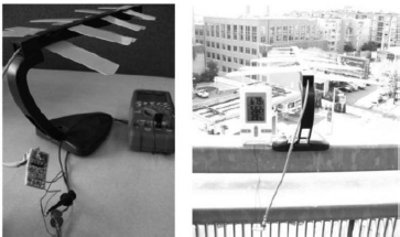
The Georgia Institute of Technology and the University of Tokyo also developed an energy harvesting system [VYA 12]. Table 4.1 indicates ambient wireless power measurements in Tokyo due to analog and digital TV broadcasts. Figure 4.3 shows ultra high frequency (UHF) and very high frequency (VHF) TV and radio broadcasts measured in Tokyo at a distance of 6.5 km from the Tokyo TV tower. In this radiowave application, the amount of wireless power required by the charge pump rectifier to charge the tank capacitor from 1.8 to 3.0 V was 38–70 W, respectively, at a frequency of 550 MHz, which is close to the wireless power captured by the antenna from UHF TV bands. The developed energy harvester is shown in Figure 4.4 and a photo of the field experiment taken in Tokyo is shown in Figure 4.5.
Table 4.1. Ambient wireless power measurements in Tokyo due to analog and digital TV broadcasts [VYA 12]

Figure 4.3. UHF and VHF TV and radio broadcast power measured in Tokyo at a distance of 6.5 km from the Tokyo TV tower [VYA 12]

Figure 4.4. Five-stage wireless energy harvesting RF charge pump circuit and PMU developed by GIT and University of Tokyo [VYA 12]
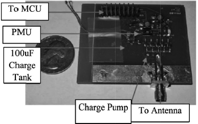
Figure 4.5. Photo of the energy harvesting field experiment in downtown Tokyo [VYA 12]

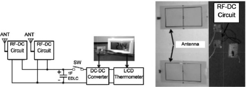
Another Japanese group carried out an energy harvesting field experiment in Nara, Japan [KIT 13]. The system was set up by the window of the researchers’ office. The measured spectrum and power density are shown in Table 4.2 and Figure 4.6. In this application, the open-circuit voltage of the RF–DC conversion circuit was 450 mV and the received power in the 800 MHz band was measured at around −20 dBm using their developed twinloop antenna. A block diagram and photo of the developed system are shown in Figure 4.7. After a charging time of 19 h, the EDLC voltage charged up to 469 mV.
Table 4.2. Measured power density in Nara, Japan [KIT 13]
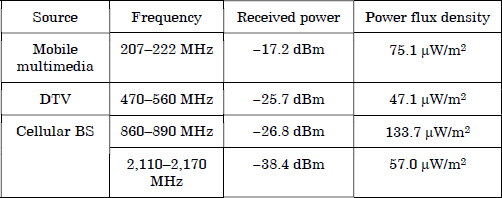
Figure 4.6. Measured frequency spectrum in Nara, Japan [KIT 13]

Figure 4.7. Block diagram and photo of the energy harvesting system [KIT 13]
An energy harvesting application has already been commercialized by Powercast Corporation in the United States [POW 13b]. The company released an energy harvester chip (Figure 4.8). The characteristics of the Powercast P2110 energy harvester are as follows:
Figure 4.8. Powercast energy harvester chip [POW 13b]

The company has a patent for a rectifying circuit for wideband radiowaves (Figure 4.9) [ENE 06].
Figure 4.9. Powercast patent for rectifying circuit for wideband radiowaves [ENE 06]

4.3. Sensor network
If users do not require a large amount of power, microwave power can drive their devices without a battery. One potential low-power device is a wireless sensor. As such, wireless power can be actively transmitted to users that require electricity (Figure 4.10).
Figure 4.10. Image of wireless powered sensors (ZigBee)

The ZigBee/IEEE802.15.4 sensor represents a potential wireless powered sensor. The ZigBee network is configured as a coordinator, a router and an end device. The coordinator is just one device in the network and coordinates the network. The router has the function of relaying data from other routers and end devices as well as sensing information. The end device only sends data; otherwise, it sleeps. Therefore, power consumption of the end device is lower than the other devices. The router and end device send a total of nearly 2 ms of data every 1.14 s. The coordinator drops either device from its network if it does not receive data from them for 15 s. The out-of-network device must perform the necessary routines to rejoin the network. When the end device and the router rejoin the network and communicate with each other, they expend 9.46 and 57.4 mW, respectively, to do so. When they do not join the network and sleep, they expend 61.8 and 57.1 mW, respectively. The electricity consumption is one example that indicates we can drive the ZigBee sensor strictly with microwave power.
Hence, pulsed microwave power operating with the same frequency as ZigBee is suitable to increase microwave power by including suppression of interference with ZigBee’s wireless communication (Figure 4.11). Experiments involving a microwave-driven ZigBee sensor and its coexistence with a pulsed microwave power and wireless communication system on the same frequency of 2.45 GHz were successfully carried out at Kyoto University, indicating that power and communication systems could operate without interference in the same environment and at the same frequency [ICH 12]. Figure 4.12 shows the experimental results of the minimum duty ratios of which the intermittent microwave power could drive the end device and error rates at the given duty ratios. The pulsed microwave with a pulse frequency of 10 Hz and a duty ratio of 0.4 could drive the ZigBee device without any interference with ZigBee communications.
Figure 4.11. Pulsed microwave power transmission whose frequency is the same as that of wireless communications

Figure 4.12. Measurement results of error rates and minimum duty ratios with which the pulsed microwave could drive the end device [ICH 12]

Another Japanese-proposed wireless powered sensor network is called wireless grid or microwave illumination – this concept is shown in Figure 4.13 [SAK 10, MAE 13]. The system provides wireless power and wireless information of active RFID in the 920 MHz band. The system uses four channels (1 W) without carrier sensing for passive RFID for wireless power. For the sensor network, 77 channels (1 mW) for active RFID are used (Figure 4.14). Instantaneous received power should be larger than the power consumed by the sensor. The average consumed power is controlled by changing the duty cycle (Figure 4.15). A multipower transmitter is used in the room and a carrier shift diversity is proposed in which multifrequencies are used to reduce standing waves in a closed room. The carrier shift diversity effectively reduced standing waves and created an approximately uniform power density in the room.
Figure 4.13. Concept of the wireless grid (Microwave Illumination) [SAK 10]
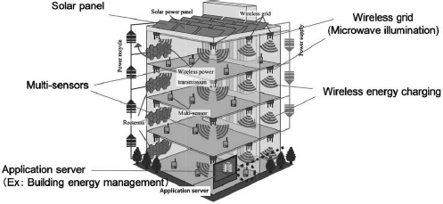
Figure 4.14. Frequency spectrum for the wireless power and sensor network in the 920 MHz band [MAE 13]
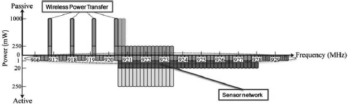
Figure 4.15. Required power delivered to the activate sensor

DENGYO Corporation in Japan provides a commercial wireless sensor using WPT in the 920 MHz band (Figure 4.16) [DEN 13]. The distance of application is less than 5 m. The RF–DC conversion efficiency is approximately 60%. The company proposes applications of the wireless sensor for sensing in high-temperature environments (85–120°C), sensing on a rotating or moving object and in severe environments, for example in outdoor or marine environments. DENGYO Corporation has developed a high-efficiency rectenna whose RF–DC conversion efficiency is approximately 86% at 2.45 GHz and 7 W [FUR 10].
Figure 4.16. Commercial wireless sensor using WPT in the 920 MHz band [DEN 13]

4.4. Ubiquitous power source
Sensors are suitable devices to take advantage of WPT via radiowaves because they are very low power devices. However, various kinds of mobile devices exist that operate using battery storage and WPT should be applied for wireless power feeding or wireless charging of these various mobile devices. For this purpose, a idea named ubiquitous power source (UPS) was proposed near the end of the 1990s [SHI 04d, SHI 05] and it is based on the idea that microwaves are everywhere at all times (ubiquitous) and are always available for WPT.
Figure 4.17. The “ubiquitous power source” concept [SHI 04]
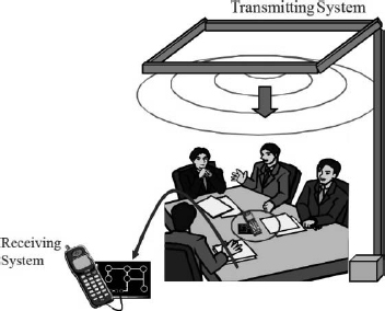
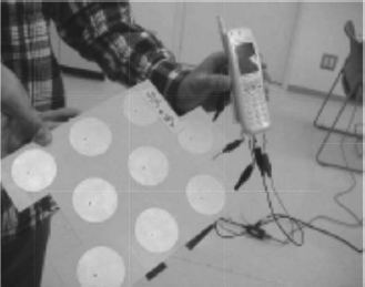
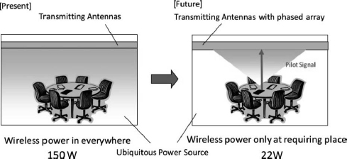
The concept of UPS is shown in Figure 4.17. Microwave power at 2.45 GHz (industrial, scientific and medical (ISM) band frequencies in the 2.40–2.50 GHz range is transmitted from the edges of a ceiling to charge mobile phones. It is quite possible to create a uniform microwave power density in a UPS room with antennas installed at the ceiling edges. Slot antennas are selected as the transmitting antennas because of their reduced cost. For the same reason, a frequency stabilized and phase controllable magnetron is used. However, because the UPS concept is based on a “wireless power source all the time and everywhere,” the design of UPS is limited by safety issues associated with prolonged exposure to microwaves by human beings. The safety level set is under 1 mW/cm2 for continuous exposure over the entire human body. For an experimental room of 5.8 m × 4.3 m, approximately 150 W of microwave power was transmitted from a magnetron to create a uniform microwave power density of 1 mW/cm2 or less. High-efficiency rectennas are also necessary for operation at a microwave power density of 1 mW/cm2 or less. Under these conditions, an experiment was successful at charging mobile phones as shown in Figure 4.18. Furthermore, a mobile phone can still be used in the UPS room because of the difference between the 2.45 GHz of microwave power and the 1.9 GHz of communication system frequencies.
Figure 4.18. Wireless mobile phone charging experiment using a UPS [SHI 04]
As an extension of UPS systems, a phased array should be used to reduce the total transmitting power and to reduce unexpected radiation at positions where power is not needed (Figure 4.19). For directional UPS in a room the size of which is equivalent to the UPS experiment described above, only 22 W of microwave power (vs. 150 W for the conventional UPS system) is required if the power density around a device is to be 1 mW/cm2. The phase array is still expensive for commercial WPT and UPS. The cost of the array depends on component costs, especially the phase shifter. Therefore, systems without phase shifters are proposed to reduce the total microwave power necessary for UPS while lowering the cost [HAS 11].
Figure 4.19. Present UPS versus future UPS using a phased array
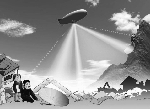
An emergency UPS was proposed and an experiment was carried out in 2009 in Japan [MIT 10], as discussed in section 1.4. An image of the experimental system is shown in Figure 4.20. Worldwide, there are some research projects involving emergency base stations for mobile phones by balloon or by airship. However, even if a base station for mobile phones is established for emergencies, a mobile phone cannot be used without electricity. So an emergency UPS system is proposed for rapid and periodic recovery of electricity by wireless power. In the experiment of 2009, a mobile phone was charged using only wireless power from an airship (see Figure 1.16).
At the TechCrunch disrupt 2013 technology conference, Ossia Corporation, a US-based company, proposed a commercial wireless charger using MPT whose frequency is the same as that of WiFi [AOL 13]. It is called “Cota” and can wirelessly deliver 1 W of power at a distance of 30 ft. In the conference, they showed an iPhone 5 being remotely charged from a prototype WPT system. The company claimed that the commercialized version of Cota will be ready to ship in 2013–2014, and a consumer version will be ready to ship before 2015.
Figure 4.20. Image of an emergency UPS system
4.5. MPT in a pipe
MPT with diffused radiowaves must observe radiowave regulations in order to coexist with conventional wireless communications and other radiowave applications. Substantial wireless power cannot yet be transmitted under present radiowave regulations owing to questions of safety for humans and other living things exposed to radiowaves, where the 1 mW/cm2 limit in the 2.45 and 5.8 GHz bands was described earlier as an example. The International Commission on Non-Ionizing Radiation Protection (ICNIRP) is the international policy group that makes safety guidelines for radiowave exposure [ICN 13].
To transmit substantial amounts of wireless power under present radiowave regulations, the concept of MPT in a pipe has been proposed and developed. The scheme has two merits. Microwaves and other radiowaves can propagate through a pipe, which serves as a waveguide, if the inside surface of the pipe consists of a conductor. In this situation, microwave power does not diffuse like it does in free space and only propagates through the waveguide. Theoretically, power loss for MPT over a distance D from a transmitter to a receiver in free space depends on the diffusion of the radiowaves in inverse proportion to the square of the distance D2, which is determined by equation [2.5] or [2.7]. However, the propagation loss in the waveguide does not depend on the diffusion of the radiowaves but depends only on the product of the propagation distance D and a loss factor, which depends on the conductivity of the inside surface of the waveguide. This loss is much smaller than the loss incurred in free space propagation. Other merits include no interference with conventional wireless communication systems and no radiation-related safety problems for humans and other living organisms because the microwave does not propagate in free space. High-power microwaves can be easily transmitted only along the waveguide. The potential magnitude of microwave power that can be transmitted is not limited by interference and safety factors but by technical issues, especially the power limits of semiconductors and microwave circuits.
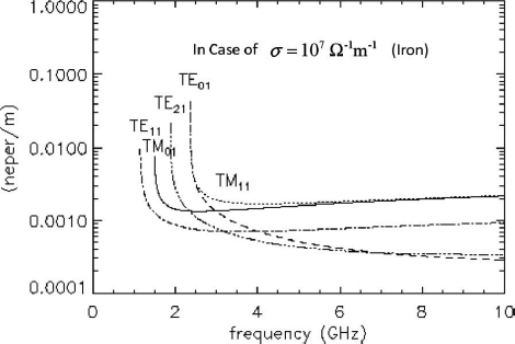
In a rectangular waveguide or a circular waveguide, a microwave propagates in a particular “mode” which is determined by Maxwell’s equations using the boundary conditions (mainly the internal size and geometry) of the waveguide. There are a number of modes that decide the impedance of the waveguide and the resulting loss through the waveguide. Figure 4.21 illustrates a theoretical propagation mode in a circular waveguide. The loss coefficient α of a TEmn mode wave and a TMmn mode wave can be estimated theoretically. Figure 4.22 illustrates the theoretical loss of a circular waveguide. Based on the theory, we can apply this MPT as MPT in a pipe.
Figure 4.21. Theoretical electromagnetic modes in a circular waveguide where the solid line denotes the electric field and the dotted line denotes the magnetic field
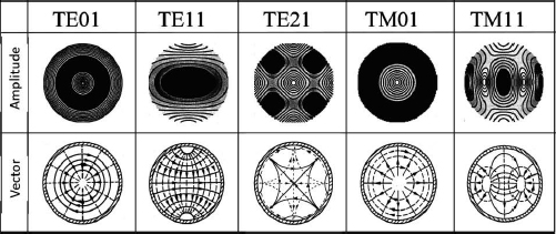
Figure 4.22. Theoretical loss of a circular waveguide
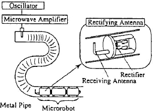
In the 1990s, in Japan, a microrobot moving in a pipe and powered by MPT in a pipe was developed. The concept is shown in Figure 4.23. Denso Corporation in Japan developed the MPT in a pipe system using 14 GHz microwaves, as shown in Figure 3.82 [SHI 97], propagating down a 15 mm diameter circular pipe, as a circular waveguide, in the TE11 mode (Figure 4.24) with a transmission loss estimated to be <1 dB/m. The rectenna which was composed of a monopole antenna and a rectifying circuit received the microwave power and fed the rectified DC power to the robot’s inertial drive system composed of a piezoelectric bimorph cell to drive the microrobot. The microrobot received 50 mW of microwave power and was able to move at a rate of 1 mm/s in the pipe when 1 W of microwave power was transmitted through the pipe.
Figure 4.23. The concept of a robot in a pipe powered by MPT [SHI 97]
In the 1990s, Kyoto University and Osaka Gas Corporation also proposed an MPT system for powering an observation robot in a gas pipe [HIR 97, HIR 99]. The size of the gas pipe was approximately 155 mm, which was suitable for the propagation of microwaves operating at a frequency of 2.45 GHz. The problems associated with this particular MPT application were (1) an unknown propagation loss in rusty gas pipes and (2) the complex branching of the gas pipe network. The propagation loss was estimated by experiments and theory and was on the order of −0.1 to −1.0 dB/m, which depended on the propagation mode, and an estimated parameter for the electric conductivity σ ≅ 104 Ω−1m−1 of the inner surface of rusty gas pipes, and σ ≅ 107 Ω−1m−1 for an ideal iron pipe. It was concluded that the loss was sufficiently low to propagate microwave power in the gas pipe.
Figure 4.24. Conventional method of power conversion from a circular waveguide to a coaxial cable [SHI 97]

The complexity of the pipe branch network posed a bigger problem. Theoretically, radiowaves cannot propagate to all branches of the waveguide, and some branches would not be serviced with radiowaves. Experimental results supported the theory, which indicated that the proposed MPT in a pipe system had limited application.
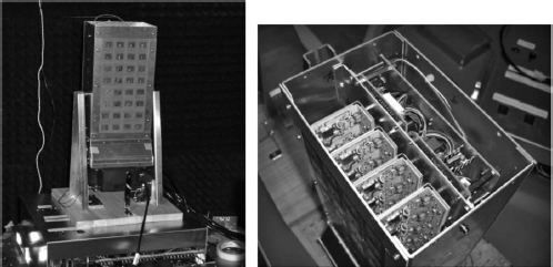
4.6. Microwave buildings
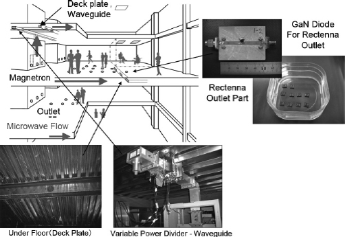
Kashima Co., a Japanese building company, jointly proposed with Kyoto University a wireless building using microwave power technology [SHI 08]. The proposed power system is shown in Figure 4.25. This system wirelessly supplied electric power using a deck plate consisting of extra cover boards that acted as microwave transmission waveguides. A frequency of 2.45 GHz was selected on the basis of size limitations of the conventional deck plate, and a magnetron was used as the microwave transmitter to reduce cost. The flow of microwave power could be controlled by variable power dividers that supplied microwave power only to users requiring it and blocked flow to places where there were no users. Rectennas as DC converters and as DC power sources were placed under the floor. Adjusting the position of the rectenna was quite easy because microwaves were present practically everywhere under the floor. Total efficiency from electricity to DC via microwave transfer was assumed to be 50%. Although the day-by-day running costs of electricity for the microwave building system is approximately twice that of a conventionally wired home, the initial cost of the building is reduced because of reduced construction costs. Therefore, it was estimated that the overall lifecycle cost of the building can be reduced by using the microwave building system.
Figure 4.25. Wireless building using microwave power transmission
A result of an electromagnetic simulation of the conventional deck plate with the extra cover board using a finite element method is shown in Figure 4.26. The fundamental TE10 mode of the 2.45 GHz microwave is clearly shown. The cutoff frequency for the TE10 mode is 1.43 GHz and the cutoff frequency for the higher mode is 2.86 GHz. This indicates that 2.45 GHz microwave power can propagate through the conventional deck plate only with the extra cover board. The deck plate is plated with zinc and it is different with commonly used waveguides. The loss of the waveguide depends on the plating inside the waveguide. The experimental results describing the loss of the deck plate are shown in Table 4.3. The loss depends on the method of connection between the deck plate and the extra cover board. Use of the deck plate as the waveguide is sufficient to support the microwave building system.
Figure 4.26. Photo of the deck plate and simulation of the wave mode in the deck plate waveguide

Table 4.3. Experimental results of power loss in the deck plate waveguide
| Connection | Attenuation constant [dB/m] |
| Spot welding | 0.69 |
| Bolted connection | 0.37 |
| Solder joint | 0.02 (0.018 by theory) |
In this system, a high-efficiency rectenna with a high power input of at least 100 W is required as the power source. If the rectenna is developed with normal Si Schottky barrier diodes, over 250 diodes are required on a single rectenna. A high-power rectenna consisting of 256 diodes was developed at Kyoto University and its RF–DC conversion efficiency was approximately 55% at 100 W, 2.45 GHz microwave input. The size of the rectenna was 125 mm in length, 110 mm in width and 95 mm in height and it is too large to be used as a power source in the proposed application.
Figure 4.27. A photograph of the developed GaN diode [TAK 09]

GaN diodes are suitable for high-power rectification. As shown in Figure 3.3, GaN is applied for mainly HPA with HEMT and FET. There is still very little research on GaN diodes. In Kyoto University and Tokushima University in Japan, a new GaN diode was developed for this application (Figure 4.27) [TAK 09]. The RF–DC conversion efficiency of the GaN diode rectenna developed is approximately 74.4% for 2.45 GHz, 5 W microwaves with a 130 Ω load (Figure 4.28). Such a rectenna would be suitable for the microwave building application.
Figure 4.28. The RF–DC conversion efficiency of the rectenna using GaN diodes. For a color version of this figure, see www.iste.co.uk/shinoharalradiowaves.zip

In the initial phase, the wireless system was considered for office buildings where DC-driven computers and other OA instruments are mainly used. It is estimated that one DC converter requires <50 W, and >3 kW of microwave power is provided to a single room, indicating that the system provides sufficient power to run a number of typical electrical devices per room. The microwave traveling through the waveguide in this application serves as a UPS system.
4.7. 2D WPT
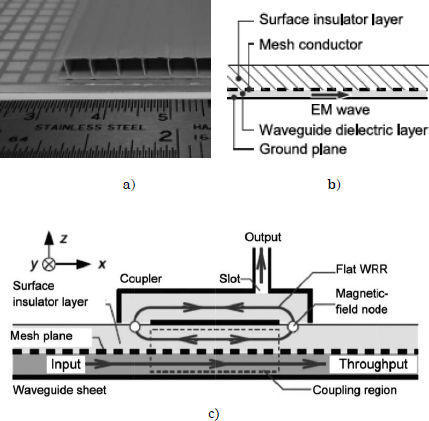
An MPT operating through closed waveguides is a good potential application under present radiowave regulations. Another MPT operating through closed waveguides was proposed and developed in Japan. It is called the “two-dimensional waveguide power transmission (2D WPT) system” [SHI 07a]. In 2D WPT systems, the microwave propagates along a waveguide sheet and is selectively received by special receiving devices on the sheet (Figure 4.29). The 2D WPT system also has an inevitable trade-off between the safety and power transmission capacity. Figures 4.30(a) and (b) illustrate an improved waveguide surface which has been demonstrated to enhance electromagnetic compatibility (EMC) performance [NOD 11, NOD 12b]. The microwave is received at a waveguide-ring resonator (WRR) coupler which extracts the power from the waveguide across a thick insulator (Figure 4.30(c)). Extraneous objects near or even touching the sheet are not exposed to the strong electromagnetic fields. The WRR coupler has a significantly high quality factor (high-Q) in the resonant state, which is essential to support the selective power transmission. The WRR is connected to a rectifying circuit which is driven in class F. The total efficiency, defined as the ratio of the DC output of the rectifying coupler to the microwave input into the sheet, was 40.4% at maximum, where the microwave input was 1 W in the 2.4 GHz band with a 6.4 × 3.6 cm2 coupler on a 56 × 39 cm2 sheet (nearly 100 times the area of the coupler) [NOD 12b].
Figure 4.29. Photographs of the 2D WPT system

Figure 4.30. Wireless power transfer sheet: a) upper view of the waveguide sheet around its edge, b) schematic drawing of its cross-section, c) receiver of wireless power [NOD 11, NOD 12b]
Microwaves are used in the 2D WPT system and the microwave diffuses in accordance with Maxwell’s equations even if the dimension decreases from three-dimensional (3D) to 2D. To suppress unexpected radiation, a phased array can be applied to the 2D WPT system, which is equivalent to a 3D WPT system [NOD 13]. Figure 4.31 shows a proposed experimental 2D WPT system using a phased array at the University of Tokyo. Results of the experiment indicated that the variation of the efficiency at a receiving point on the sheet using the phased array is suppressed within 2 dB, whereas the variation was more than 10 dB without the phased array system.
Figure 4.31. Block diagram of the microwave power supply system using a phased array which has seven RF amplifiers along each edge [NOD 13]

4.8. Wireless charging for electric vehicles
Highly efficient MPT can be applied not only through closed waveguides, but also over short distances with smaller antennas as shown in Figure 2.3. Photographs of the wireless charging of an electric vehicle (EV) using MPT are shown in Figure 4.32. It is convenient to apply MPT for wireless charging both for parked EVs and for EVs in motion because the transmitting and receiving antennas are not coupled. The impedance of the antennas is not changed by a change in the position of the EV nor is the efficiency of MPT changed. Problems of safety and interference by microwaves are diminished for both MPT in a closed waveguide and over short distances because there is almost no diffusion of unexpected microwaves. In short-distance power transfer systems, the magnitude of wireless power can also be increased to the kW range because the transmission does not interact with humans or other living organisms between the transmitting and receiving antennas.
Figure 4.32. Images of wireless charging of EVs a) for parked EVs and b) for EVs in motion

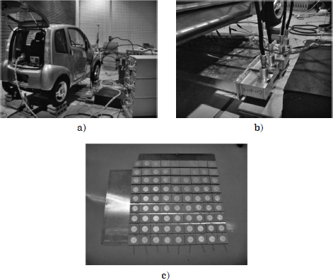
Kyoto University has proposed and implemented an MPT system for EVs (Figure 4.33) [SHI 04]. From 2003 to 2008, the university first collaborated with Nissan Motors to develop an MPT system between the road and the body of an EV using a microwave frequency of 2.45 GHz (Figure 4.34) [SHI 11a, SHI 11b]. Magnetrons and slot antennas were used to reduce the system cost. The distance between the transmitting and the receiving antennas was approximately 12.5 cm, a distance of 1 λ at the 2.45 GHz frequency. The battery on the electric vehicle can be effectively charged using microwave transmissions having a theoretical beam efficiency of at least 83.7% and an experimental beam efficiency of at least 76.0% [SHI 11b]. This efficiency is sufficiently high to realize the transmission of wireless power using microwaves. For this application, a new GaN Schottky diode was utilized to increase the rectified power and to reduce the EV charging time.
In 2000, a scaled MPT model for running an EV was developed at Kyoto University [SHI 04]. To reduce power loss, the position of the model EV was detected by positioning sensors and microwave power was transmitted only to the position of the model EV.
Figure 4.33. Short-distance wireless microwave charging road system for EVs [SHI 04]

Figure 4.34. Wireless charging experiment with microwaves by Kyoto University: a) the system, b) microwave transmitting antenna on the road and c) rectenna array on the body of the EV [SHI 11b]
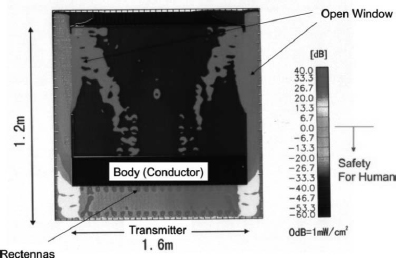
In total, 1–10 kW of microwave power is required to charge the EV. Although the short distance between the transmitting and receiving antennas is an advantage for suppression of unexpected radiation, estimation of the unexpected radiation and a plan to suppress it are essential. Figure 4.35 shows simulation results by the finite difference time domain (FDTD) method of radiation in the system for wireless charging of EVs [SHI 13d]. The radiated microwave was 5 kW at a frequency of 2.45 GHz. A dipole antenna connected to a 50 Ω resistance was positioned on the body of the EV. The body and the roof of the EV were metallic and the windows were unshielded (open). Except between the transmitting and receiving antennas, a safe power density below 1 mW/cm2 was satisfied.
Figure 4.35. Simulated radiation by the FDTD method of wireless charging of EVs [SHI 13d]. For a color version of this figure, see www.iste.co.uk/shinohara/radiowaves.zip
From 2006 to 2008, Mitsubishi Heavy Industries Ltd. in Japan conducted an MPT R&D project for EVs with Mitsubishi Motors Co., Fuji Heavy Industries Ltd., and Daihatsu Motor Co., Ltd., at Kyoto University [SHI 13a]. To reduce the power loss, they used: (1) 6.6 kV directly to drive the 2.45 GHz magnetrons as microwave transmitters, (2) a blocking wall around which microwaves pass between the transmitting antennas and receivers and (3) a heat recycling system. The total efficiency, including the heat recycling, was approximately 38% with an output power of 1 kW at a distance of 12.5 cm. The prototype released in 2009 is shown in Figure 4.36.
Figure 4.36. Wireless charging experiment with microwaves by Mitsubishi Heavy Industries’s group in 2009 [SHI 13a]

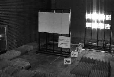
In 2012, the Volvo Technologies, Japan group, Nihon Dengyo Kosaku Ltd., and Kyoto University began to develop a new MPT system for an electric track. The former system led to mutual coupling problems between the transmitting and receiving antennas because the MPT distance was too short; therefore, the new MPT system was changed from a road-to-body to a top-to-roof configuration (Figure 4.37) [SHI 13d, SHI 13e] to take advantage of the MPT as long distance WPT. The distance between the transmitting antennas and the receiving antennas on the rooftop of the EV was 2–6 m, depending on the type of EV used. To keep a high efficiency over the varying distance, a phased array system that can create a flat beam on the receiving antennas was proposed. On July 6, 2012, Volvo Technologies, Japan, and Nihon Dengyo Kosaku Ltd. released a 10 kW rectenna array with an efficiency of 84% operating at a frequency of 2.45 GHz for the mid-distance WPT system (Figure 4.38) [FUR 13]. The received microwave power density was over 3.2 kW/m2 at a distance of approximately 4 m from the transmitter.
Figure 4.37. Proposed mid-distance wireless charging for EV and the FDTD simulation of the microwave beam [SHI 13]. For a color version of this figure, see www.iste.co.uk/shinohara/radiowaves.zip

Figure 4.38. Photograph of the 10 kW rectenna operating at 2.45 GHz for wireless charging of EVs [FUR 13].
4.9. Point-to-point WPT
It is easy to show a point-to-point WPT via radiowaves in distances of over a kilometer instead of a wired power transfer. In the 1960s, point-to-point WPT operating in the km range via microwaves was highly expected for WPT application. Brown and Dickinson carried out MPT experiments at jet propulsion laboratory (JPL) in 1975 [BRO 84]. However, the size of the transmitting and receiving antennas was decided by theory, and they were too large to realize a commercial point-to-point MPT application with reasonable cost as an alternative to wired power transfer. Point-to-point MPT systems were revised and further experiments were proposed and carried out in the 1990s [SHI 98a, CEL 97]. Under certain conditions, such as providing electrical power to an isolated mountain top or an island where the cost of a wired power supply is too expensive and/or electric power needs are sporadic, the point-to-point MPT system has a distinct advantage over wired power transfer.
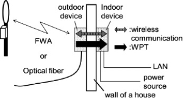
The size of the antenna and the expense of an MPT system depends on the MPT’s intended range. In Japan, a short-distance point-to-point MPT system has been proposed by Nippon Telegraph and Telephone Corporation (NTT Corp.) and Kyoto University, which is called MPT for fixed wireless access (FWA). Figure 4.39 shows an image of the proposed system [HAT 12]. The outdoor device communicates with the Internet by the FWA or an optical fiber. The inside device and the outside device wirelessly communicate with each other. The inside device transmits power to the outside device by microwave. The outside device can operate without a battery. For the system, it is preferred that both information and power are carried by the same microwave carrier to reduce the size of the system. First, a frequency of 24 GHz was selected and an MMIC rectenna with a class-F load output filter was developed, as shown in Figure 3.83 [HAT 13].
Figure 4.39. Concept of a microwave-driven FWA system [HAT 12]
4.10. WPT to moving/flying target
Previous MPT experiments conducted during the SHARP, MILAX and ETHER projects aimed at a stationary high-altitude relay platform in the stratosphere. MPT is the most suitable WPT for a moving/flying target. A phased array is required to control the microwave beam form and direction as was described in section 3.4.
In the early 21st Century, the MPT to microaerial vehicle (MAV) [MIY 12] and Mars observation airplane [NAG 11b, NAG 12] projects, which were MPT systems directed toward small airplanes, were proposed and developed in Japan. The MPT to the MAV was proposed by the University of Tokyo. Researchers transmitted 5.8 GHz microwave power to a flying MAV from which a pilot signal of 2.45 GHz was transmitted as a signal for target detection. Rectennas were installed on the body of the MAV. Initially, five horn antennas were used as a phased array (Figures 4.40 and 4.41). The diameter of the phased array was 330 mm and its element spacing was 2λ. Microwave power from the horn antennas was 4 W each. For the base system, a phased array using eight microstrip antennas whose element spacing was 1.36 λ was adopted. Microwave power from the microstrip antennas was 8 W each.
Figure 4.40. First concept of an MPT to micro-aerial vehicle [MIY 12]

The Mars observation microwave airplane system was proposed by Kyoto University and Kyusyu Institute of Technology, Japan. Wide-ranging continuous observation of the surface of Mars is of importance for understanding the physical properties of that planet. The surface of Mars has mainly been observed by a rover, which can neither move rapidly nor observe bumpy areas. Therefore, small airplane observation is receiving attention as an alternative to the rover. To realize stable flight in the greatly reduced atmosphere of Mars, the weight of the airplane must be reduced. MPT is an excellent possible technology to reduce or even eliminate the fuel requirements of an airplane. A description of a possible future Mars observation airplane is shown in Figure 4.42 [NAG 11b, NAG 12]. An experimental setup is shown in Figure 4.43. The MPT system using a phased array antenna composed of the “power-variable phase-controlled magnetrons (PVPCMs)” was used in the experiment. The PVPCM is a derivative technology from the phase-controlled magnetron (PCM) developed at Kyoto University. A PVPCM can transmit 2.45 GHz, 61 dBm microwave power and can control the beam direction using phase control [NAG 11b]. The transmitter traces the airplane’s location with a camera using an image processing application [NAG 12].
Figure 4.41. a) Block diagram of a phased array MPT transmitter and b) photograph of the phased array

Figure 4.42. A description of the MPT to Mars observation airplane [NAG 11b, NAG 12]
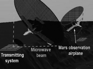
Figure 4.43. a) Schematic diagram and photograph of the magnetron-based phased array and b) alignment of the six rectennas on the airplane body for ground experiments [NAG 12]

MPT to a moving rover is another potential application. From 2004 in Japan, MPT using active integrated antenna (AIA) technology was developed as a spin-off technology from SPS [SHI 07b]. The target of this project was: (1) development of a very light power-to-weight ratio microwave power transmitter using AIA technology (with a target below 50 g/W), (2) advancement of the power management of the rectified microwave power at the rectenna, receiver and rectifier of the microwave power, especially against changes in the connected load and (3) fundamental experiments of the coexistence of 100 W microwaves and 10 mW wireless communication waves. For the target of the project, MPT to a moving rover was chosen. Figure 4.44 shows the experimental system. The system block diagram is shown in Figure 4.45. The microwave transmitting subsystem was mainly developed at Kyoto University. The microwave transmitting subsystem was composed of a 32 element AIA with a linear polarized rectangular microstrip antenna array and 4W output three-stage GaAs high-power amplifiers on a bent dielectric base for an expanded cooling area, whose total power is 120 W at 5.8 GHz. The system uses no phase shifter. Figure 4.46 shows the developed microwave transmitting subsystem. The total weight of the 120 W system is approximately 4 kg and the power-to-weight ratio is approximately 33.3 g/W. The volume of the subsystem is 0.0544 × 10⁻³ m3 (0.17 × 0.12 × 0.32 m).
Figure 4.44. Experimental system of MPT for the moving rover [SHI 07b]

Figure 4.45. Block diagram [SHI 07b]

Figure 4.46. Developed microwave transmitting subsystem with 32 AIA elements and a bent dielectric base for an expanded cooling area [SHI 07b]
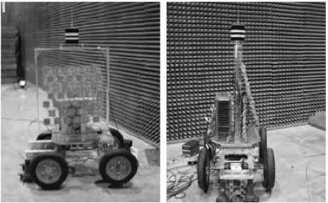
The microwave receiving subsystem was mainly developed at IHI Aerospace. For target detection, supersonic waves and a small turn table were adopted. The microwave beam emitted from the microwave transmitting subsystem positioned on the turn table tracked the rover. A photograph of the MPT experiment in an anechoic chamber is shown in Figure 4.47. The rover moved only by means of the microwave power provided by MPT.
Figure 4.47. Photograph of the MPT rover experiment [SHI 07b]

The MPT-rover was applied to an agricultural application. Electrification of agricultural vehicles is one solution to address environmental issues, such as global warming and fossil fuel resource shortages. Lead–acid batteries, however, are heavy and have low power density for agricultural usage. So a microwave-driven agricultural model vehicle was proposed and developed at Kyoto University [OID 07, MIY 13].
The microwave-driven vehicle was built as a model of a small type seeder. The vehicle was equipped with a driving motor (24 V rated voltage, 26 W rated output). A rotary encoder was attached to the drive shaft to measure the vehicle speed. For steering, a DC motor (24 V rated voltage, 14.8 W rated output) was used. The actual steering angle was measured using a rotary potentiometer attached to the steering motor shaft. A rectenna panel was installed on the vehicle as shown in Figure 4.48 [MIY 13].
Figure 4.48. Microwave-driven agricultural model vehicle [MIY 13]
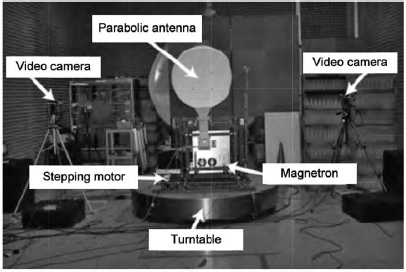
The transmitter system is shown in Figure 4.19 [MIY 13]. Microwave power to the vehicle was generated by a magnetron operating at a frequency of 2.45 GHz and transmitted from a parabolic antenna positioned on a turn table. Two monochrome charge coupled device (CCD) cameras mounted on stepper motors were used to capture images of the cylindrical stripe marker mounted on the experimental vehicle. The magnetron output was 800 W, and the maximum total power consumption of the vehicle was approximately 41 W at a distance of a few meters. The vehicle could be solely moved by the microwave power.
Figure 4.49. The transmitting system for the microwave-driven agricultural model vehicle [MIY 13]
4.11. Solar power satellite
4.11.1. Basic concept
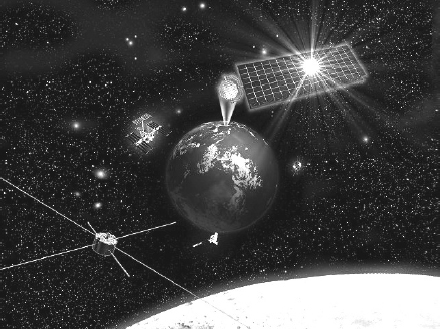
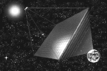
As previously mentioned, SPSs have been the most suitable application of the MPT since the 1960s because SPSs cannot be realized without MPT. The concept of the SPS is very simple. It is a very large satellite designed as an electric power plant orbiting in a geostationary earth orbit (GEO) 36,000 km above the Earth’s surface. An artistic image is shown in Figure 4.50. It consists of mainly three segments: a solar energy collector to convert the solar energy into DC electricity, a DC-to-microwave converter and a large antenna array to beam down the microwave power to the ground. The solar collector can be either photovoltaic cells or solar thermal turbine. The DC-to-microwave converter can be either a microwave tube system and/or a semiconductor system. The third segment is a large phased array. The power beam must be controlled accurately to less than 0.0005°. The SPS system is composed of a space segment and a ground power receiving site. The latter uses a device to receive and rectify the microwave power beam, namely a rectenna array. The rectenna converts the microwave power back to DC power, and is connected to existing electric power networks. The first SPS was proposed by Glaser in 1968 [GLA 68]. After the proposal of the SPS, there were, and continue to be, many SPS research projects worldwide [GLA 93, URS 07, SHI 12b].
Figure 4.50. Solar power satellite (artist conception)
The SPS system has an advantage in that it produces electricity with a much higher efficiency compared with a photovoltaic system on the ground. Because the SPS is placed in space in a GEO, there is no atmospheric absorption; therefore, the solar input power has about 30% higher density compared with the ground solar power density, and is available 24 hours a day (except for at most 70 minutes during 42 days near the equinoxes) without being affected by weather conditions. The solar flux is approximately eight times higher in space than the longterm surface average on the ground if the insolation is 4 kWh/m2/day. However, for terrestrial systems, the efficiency, additional space required to compensate for the losses and cost of the storage system should be taken into consideration in order to supply uninterrupted electricity. This ratio would become higher depending on the efficiency because 100% efficiency is assumed in the storage system. Possible issues to be discussed regarding the SPS system include the effect of the microwave power beam on existing communication networks and organisms.
4.11.2. SPS as a clean energy source of CO2-free energy and for a sustainable humanosphere
The CO2 emissions per kWh of different electricity generation systems (such as fossil fuels and nuclear power) are compared to SPS, as shown in Table 4.4 [YOS 09]. The CO2 emitted from the operation of fossil fuel power generation systems is mainly due to the burning of fuel, whereas the CO2 emissions from nuclear power plants are mainly due to the use of energy to produce the nuclear fuel. Almost zero CO2 emissions are expected from SPSs during operation. As a result, the SPS system would generate less CO2 per kilowatt hour than nuclear power generation.
To ensure the sustainability of economic activities, there is a need for the development of a large-scale and clean power source that sufficiently suppresses CO2 emissions. It is generally accepted that only solar technologies can provide such a large-scale and clean power source in the near future. Terrestrial photovoltaics, wind, geothermal and other natural resources depend on the environmental conditions, and they are neither stable nor sufficient in quantity.
Table 4.4. Comparison of relative CO2 emissions from different electricity generation systems (units: g CO2 per kWh)

Considering the Earth as a global system or as “Gaea,” the SPS can contribute to a sustainable humanosphere, which includes the Earth and a space system. The Club of Rome, in the “Limits to Growth” on the Earth in 1972 [MEA 72], indicated that the influence of human activities on the Earth, such as the exhaustion of natural resources, pollution of the air, the greenhouse effect, etc., had increased significantly, as previously predicted by Forrester [FOR 73] who performed simulations of world dynamics models. Figure 4.51 shows a basic simulation result of a modified version of Forrester’s WORLD-2 model [YAM 92]. For such “Limits to Growth” in the closed Earth system, the SPS will provide the world dynamics model with new boundary conditions and provide new solutions. Figure 4.52 shows a revised simulation result of a world dynamics model incorporating SPSs [YAM 92]. Compared with the result in Figure 4.51, the simulation result shown in Figure 4.52 suggests that the SPS can provide a new solution to remove the limitations to growth. The SPS is one of the potential technologies that can support our life and the Earth, which is called a “sustainable humanosphere” that is open to space systems.
Figure 4.51. Simulation result of Forrester’s WORLD-2 model (modified version). Full-scale values of levels: population (P = 1 × 10¹⁰ (People)), capital investment (CI = 2 × 10¹⁰ (capital unit)), total energy resources (NR = 3.24 × 10¹³ (barrels)),oil (NRO = 2 × 10¹² (barrels)), CO2 (CO2 = 1,000 (PPM)), quality of life (QL = 2), food ratio (FR = 2) [YAM 92]
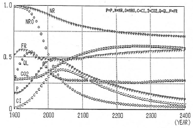
Figure 4.52. Simulation result of revised world dynamics model with SPS (high-energy investment case). Full-scale values of levels: population (P = 1 × 10¹⁰ (people)), capital investment (CI = 5 × 10¹⁰ (capital unit)), SPS number (N = 4,000), oil (NRO = 2 × 10¹² (barrels)), CO2 (CO2 = 1,000 (PPM)), quality of life (QL = 2). Parameters: energy investment in SPS (Et = 0.003 × NRUR (MJ)), start year of energy investment: (IYEAR = 2000 (Year)), SPS research cost to improve value (RYEAR = 2100), SPS CI discard normal (SCIDN = 0.001) [YAM 92]

4.11.3. MPT on SPS
In the MPT system of the SPS, a large phased array with a high efficiency must be used. The phased array is necessary for steering a power beam to a small rectenna target on the ground within a tolerance of 0.0005°, although the transmitting antenna of the SPS will always move and fluctuate. The power beam must be generated and transmitted without much loss for economic reasons. An economic analysis in Japan indicated that the optimum size of the transmitting phased array should be a few kilometers and the optimum microwave power should be approximately a few GW with a frequency of 2.45 GHz. For the same reason, the DC–RF conversion efficiency (which includes all losses, e.g. in phase shifters, power circuits and isolators) is assumed to be more than 80%. The beam collection efficiency, defined as the ratio of the microwave power received at the rectenna site to the microwave power emitted from the transmitting antenna, which is basically estimated using equation [2.7], is assumed to be approximately 90%. The absorption by the atmosphere is estimated to be below 2%. The weight is also an important parameter of the transmitting antenna for cost estimation. The MPT system, which includes the generator/amplifier, phase shifter and antenna, must be less than several kg/kW to reduce the transportation cost.
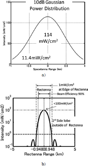
Table 4.5 shows some typical parameters of the transmitting antenna of the SPS. An amplitude taper on the transmitting antenna is adopted in order to increase the beam collection efficiency and to decrease the side-lobe levels in almost all SPS designs. A typical 10 dB Gaussian amplitude taper is used, in which the power density in the center of the transmitting antenna is 10 times larger than that on the edge of the transmitting antenna.
Table 4.5. Typical parameters of the transmitting antenna of the SPS
| Model | NASA/DOE model [DOE 78] | JAXA Model [JAX 05] |
| Frequency | 2.45 GHz | 5.8 GHz |
| Diameter of transmitting antenna | 1 kmϕ | 1.93 kmϕ |
| Amplitude taper | 10 dB Gaussian | 10 dB Gaussian |
| Output power (beamed to earth) | 6.72 GW | 1.3 GW |
| Maximum power density at center | 2.2 W/ cm2 | 114 mW/cm2 |
| Minimum power density at edge | 0.22 W/ cm2 | 11.4 mW/cm2 |
| Antenna spacing | 0.75 λ | 0.75 λ |
| Power per antenna (Number of elements) | Max. 185 W (97 million) | Max. 1.7 W (1,950 million) |
| Rectenna Diameter | 10 km × 13.2 km | 2.45 kmϕ |
| Maximum Power Density | 23 mW/cm2 | 100 mW/cm2 |
| Collection Efficiency | 89 % | 87 % |
Details of the microwave beam in the Japan Aerospace Exploration Agency (JAXA) model, which was designed in 2004, are shown in Figure 4.53. Microwave power must remain less than 1 mW/cm2 outside the rectenna. Compared to the National Aeronautics and Space Administration (NASA)/Department of Energy (DOE) model, which was designed in 1978, the microwave power density on the ground for the JAXA model is greater because Japan is a small country, and the ground system must be smaller.
Figure 4.53. JAXA model: a) power distribution on transmitting antenna whose size is 1.93 km and whose microwave power is 1.3 GW and b) power distribution on rectenna on ground whose size is 2.45 km
4.11.4. Various SPS models
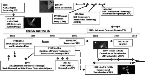
The SPS is the largest and most suitable application of MPT. In Japan, USA and Europe, many studies on SPS have been and are currently being carried out. Figure 4.54 shows committee activities concerning SPS feasibility studies from the 1970s to the present day. The activity had already started in 1977 when the NASA/DOE report was issued. Since then, the committee’s activities that were carried out to survey the conceptual design and the feasibility of SPS have continued intermittently up to the present.
Figure 4.54. Historical review of global SPS research projects
4.11.4.1. SPS in the United States
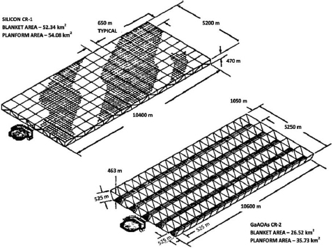
Following Glaser’s first proposal of the SPS, the United States conducted an extensive feasibility study in 1978–1980. This study was done by a joint effort of NASA and the DOE. They proposed an improved model known as the NASA/DOE reference model in 1979, as shown in Figure 4.55 [DOE 78].
According to this model, a 50 km2 solar array collects the energy of approximately 70 GW as the sun provides energy of about 1.37 kW/m2 (137 mW/cm2) at GEO, and generates 9 GW of DC power (a total efficiency of 13%). This system transmits microwave power of 6.72 GW at 2.45 GHz from a 1 km diameter antenna (78% in conversion efficiency). The number of antenna elements in the SPS would be 100 million in the case of an array antenna with an element spacing of 0.75λ. A 10 dB Gaussian taper is assumed for power distribution in the transmitting antenna in order to obtain a better power collection efficiency. A 10 km diameter rectenna on the ground site at the equator collects 5.8 GW (power collection efficiency of 89%), and 5 GW is sent to the utility grid. The number of rectenna elements is 10 billion with an element spacing of 0.75λ. If the rectenna site is located at a latitude of 35°, its shape should be an ellipse with dimensions 10 km × 13.2 km. Detailed parameters of the MPT are shown in Table 4.5. The overall system efficiency is 7%.
Figure 4.55. NASA/DOE SPS reference model [DOE 78]
From the viewpoint of EMC, consideration should be given to ensure the safety of people on the Earth. Although the power density is 23 mW/cm2 at the center of the array, it is just 1 mW/cm2 at the edge. The latter satisfies the safety standard, and even the former is a quarter of the solar radiation (100 mW/cm2). Note that solar radiation is weaker on the ground than in space because of atmospheric absorption.
The architecture of the NASA/DOE reference model entailed using a series of 60 SPSs into GEO. Each of these SPSs was planned to provide a dedicated base-load power ranging from 5 to 10 GW of continuous energy. The platforms were envisioned to be deployed using a massive, unique infrastructure. This infrastructure included a fully reusable two-stage-to-orbit (TSTO) Earth-to-orbit (ETO) transportation system, as well as a massive construction facility in low Earth orbit (LEO). For the construction, hundreds of astronauts would have been required to work continuously in space for several decades. The financial impact of this deployment scheme was significant. In 1996, more than $250 billion was estimated to have been required before the first commercial kilowatt-hour would have been delivered.
Although the SPS research has been suspended in the USA since 1980 because of the high estimated cost at that time, it was not abandoned because of its good potential as a new power source for the next generation. According to the pre-set policy of re-evaluation of the SPS with an appropriate time interval, the Fresh-Look-SPS concepts have been envisioned from 1997 as an improved SPS reference system [MAN 97].
The “Sun Tower” SPS concept is one of their new models that exploits several innovative approaches to reduce the development and lifecycle cost of an SPS, at the same time broadening market flexibility. The concept will entail relatively small individual system components with an extensively evolvable modularity, as depicted in Figure 4.56. Manufacturing can be a “mass production” style from the first satellite system. Therefore, this system can be developed at a moderate price, can be ground-tested with no new facilities and can be demonstrated in a flight environment with a subscale test. This system will initially be deployed in a LEO before subsequent migration to a GEO. This is necessary to achieve extremely low launch costs (of the order of $400 per kg), with payloads of greater than 10 MT; this is consistent with highly reusable space transportation (HRST) system concepts.
Figure 4.56. The “Sun Tower” SPS concept (MEO constellation) [MAN 97]
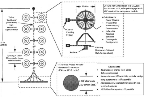
The “Sun Tower” SPS concept is a constellation of medium-scale, gravity gradient-stabilized satellites. Each satellite resembles a large, Earth-pointing sunflower in which the face of the flower is the transmitter array, and the “leaves” on the stalk are solar collectors. The concept is assumed to transmit 5.8 GHz from an initial operational orbit of 1,000 km, and be sun-synchronous at a transmitted microwave power level of about 200 MW. The total beam-steering capability is 60° (30°). Therefore, a single transmitting element is projected to be a hexagonal surface that is approximately 5 cm in diameter. These elements are pre-integrated into “subassemblies” for final assembly on orbit. For an RF transmitting power of 200 MW, the transmitter array is an “element and subassembly-tiled plane” that is essentially circular, approximately 260 m in diameter and 0.5–1.0 m in thickness.
Sunlight-to-electrical power conversion must be modular and deployable in “units,” about 50–100 m in diameter and should have a net electrical output of 1 MW. The primary technology option is a gossamer-structure based on the reflector with non-dynamic conversion at the focus (e.g. advanced solar cells). These sunlight collection systems are presumed to be always sun-facing (with the system in the sun-synchronous orbit) and to be attached regularly in pairs along the length of a structural/power transmitting tether to the backplane of the transmitter array. Heat problems occur both at the surface of the solar cell array and in the transmitter circuit. For both cases, heat rejection for power conversion and conditioning systems is assumed to be modular and integrated with power conversion systems. In the case of the transmitter, the heat rejection is assumed to be both modular and integrated at the “back-plane” of the transmitter array. Single power transmission lines from the central tether attachment point to the backplane are integrated with the modular subassemblies of the array.
The nominal ground receiver for the Sun Tower concept is a 4 km diameter site with a direct electrical feed into the interface with commercial power utilities. The space segment is consistent with a variety of ground segment approaches. However, during the early years of operation, multiple ground stations would be required to achieve reasonable utilization of capacity. For primary power, a ground-based energy storage system would be required, in particular, in the early phases of the overall system deployment in which only a single Sun Tower is operational. A pair of a single satellite and a ground receiver would be sized to approximately 100–400 MW scale, with multiple satellites required to maintain constant power at that level.
After the Fresh-Look Study of the SPS, some SPS research projects were initiated in the United States, which were called the concept definition study (CDS) in 1998, SSP Exploratory Research & Technology (SERT) in 1999–2000 and SSP Concept and Technology Maturation Programs (SCTM) in 2001–2002, respectively [FEI 03]. Through these SPS projects, two new SPS concepts were proposed: Abacus Reflector and Integrated Symmetrical Concentrator (ISC) [FEI 03]. Although SPS was considered in the United States after the SCTM [MAN 09], the ISC is the latest SPS concept present in the USA in 2013.
Figure 4.57. Concept of integrated symmetrical concentrator (ISC) [MAN 09]

4.11.4.2. SPS in the EU
In 2001, the Europeans proposed a Sail Tower SPS, as shown in Figure 4.58 [SEB 01, SEB 04]. The Sail Tower design is similar to NASA’s Sun Tower SPS, but uses a thin-film technology and innovative deployment mechanisms developed for solar sails. The main characteristics are summarized in Table 4.6.
Figure 4.58. Concept of solar sail [SEB 04]

Each sail has dimensions 150 m × 150 m and is automatically deployed by extending four lightweight diagonal carbon fiber (CFRP) booms, which are initially rolled up on a central hub. They demonstrated the CFRP booms [LEI 03]. The power generated within the sail modules is transmitted through the central tether to the antenna, where 2.45 GHz microwaves are generated in mass-produced inexpensive magnetrons. Slotted waveguides made with carbon fiber are used as active antenna elements that are mounted on the main antenna structure. For the phased arrays, several sets of waveguides radiate the microwave power to the rectennas on the Earth, where the power is transformed and fed into the existing power distribution networks. The power intensity across the antenna surface is assigned with a truncated 10 dB Gaussian distribution that minimizes side lobes and scatterings.
Table 4.6. Characteristics of solar sail

In 2003, the Advanced Concepts Team (ACT) of the European Space Agency (ESA) began a three-phased, multiyear program related to solar power from space [SUM 03]. In Europe, terrestrial solar power is one of the fastest growing energy sectors with high growth rates that have been sustained over more than a decade, with very promising forecasts. The first phase of the European Program Plan, therefore, involved the terrestrial research community and was dedicated to the assessment of the “general validity” of space concepts for Earth power supply by comparing them with equivalent terrestrial solar concepts. In parallel, the “general validity” of SPS concepts for space exploration and applications were assessed by comparing them with traditional solutions and nuclear power sources.
In January 2005, they summarized the project as follows [ESA 05]:
Whereas terrestrial solar energy is most economical for supplying power at relatively low (PV) to medium/high load-factors (SOT), space-based solar power is better suited to supplying continuous power and power at high load-factors.
Although the ACT of the ESA has maintained the SPS research activity, its activities have decreased to compared before 2005.
4.11.4.3. SPS in Japan
As shown in Figure 4.44, many SPS research projects have been initiated in Japan. From 1991 to 1993, New Energy and Industrial Technology Development Organization (NEDO) conducted an SPS research project in Japan, which was triggered by the then Japanese Prime Minister Toshiki Kaifu, who launched “New Earth 21,” which included the SPS. The SPS research committee, whose secretariat was the Mitsubishi Research Institute, Inc., was established in 1991 with 16 members and four Working Groups (WGs). The designed SPS is shown in Figure 4.59 [MIT 94]. The SPS can supply 1 GW on the ground via a 2.45 GHz microwave from the SPS in GEO. First, the SPS is launched to LEO (LEO < 400 km) and is built as shown in the lower right part of Figure 4.59. The initial SPS in the LEO is transported to the GEO as it is, and opens out to its final SPS shape using a centrifugal force. The solar cells are opened on a flexible and light film structure and are supported by control satellites. The weight was estimated at approximately 21 kilotons. Both Si and a-Si were considered as materials for the solar cells on the SPS. The efficiency of the Si was estimated to be approximately 22% with a unit of 10 cm × 10 cm whose thickness was 30 μm. The efficiency of the a-Si was estimated to be 20% with a thickness of 120 μm. The total area of the solar cells was estimated to be 10 km2, with a weight of 2,300 tons in the case of the Si and area of 11 km2, and 1,840 tons in the case of the a-Si, respectively. The generated electric power is transmitted to a 30 kVAC, 200 kHz MPT phased array. An inductive coupling was adopted as a rotary joint in the connection between the transmission path and the MPT phased array.
Figure 4.59. Japanese SPS designed by NEDO SPS committee in 1993 [MIT 94]
Klystrons were mainly adopted in the MPT system, and the semiconductor system was considered simultaneously. The power distribution on the MPT phase array is Gaussian. The maximum power density at the center is 4.48 kW/m2 and the minimum at the edge is 448 W/m2. The antenna element is a dipole with a reflector that can be used as a heat radiator. On the ground, the power density is 23 mW/cm2 at the center of the rectenna array and less than 1 mW/cm2 at the edge, respectively. The size of the rectenna on the ground is 10 km × 13 km at sea level.
The Institute of Space and Astronautical Science (ISAS) SPS Working Group, which was formed in 1987, has been engaged in four research projects, one of which is the conceptual design study of a strawman SPS, which was later designated as SPS2000 [NAG 94]. The primary objective of the study was to gain practical knowledge about problem areas of research for SPS systems. A preparatory study was conducted by a special team in the WG for 1 year [NAG 91]. Later, more researchers and groups from the industry and other universities were invited to participate in the first phase design activities. Consequently, 48 members were registered in the task team. The first phase study for the conceptual design was completed in July 1993 [SPS 93]. The design concept of the SPS2000 was to realize a “small and realistic” experimental SPS that is powered from space to developing nations at the equator.
The general configuration of SPS2000 has a shape like that of a triangular prism with a length of 303 m and sides of 336 m, as shown in Figure 4.60. The prism axis is in the latitudinal direction and is perpendicular to the direction of orbital motion. The power transmission antenna, spacetenna, is built on the bottom surface facing the Earth, and the other two surfaces are used to deploy the solar panels.
Figure 4.60. General view of SPS2000 [NAG 94]

SPS2000 orbits in an equatorial LEO at an altitude of 1,100 km. The orbit is chosen such that it minimizes the transportation cost and the distance of power transmission from space. The spacetenna is constructed as a phased array antenna. It directs a microwave power beam to the position where a pilot signal is transmitted from a ground-based segment of the power system, the rectenna. Therefore, the spacetenna has to be a physically large-size phased array antenna with a retrodirective beam control capability. Therefore, microwave circuits are connected to each antenna element and are driven by DC power generated in the huge solar panels. The frequency of 2.45 GHz is assigned to transmit power to the Earth. The ranges of the beam scan angle are ±30° for the longitudinal direction and ±16.7° for the latitudinal direction. Figure 4.60 also shows a scheme of the microwave beam control and rectenna location. SPS2000 can exclusively serve the equatorial zone, especially benefiting geographically isolated lands in developing nations. The spacetenna has a square shape whose dimensions are 132 m × 132 m, and which is regularly filled with 1,936 subarray segments. The subarray is considered to be a unit of phase control and is a square-shaped array of sides 3 m. It contains 1,320 units of cavity-backed slot antenna elements and DC–RF circuitry. Therefore, there will be approximately 2.6 million antenna elements in the spacetenna.
The JAXA, formerly National Space Development Agency (NASDA), established an SPS research committee in 1998 (until 2007) and studied the SPS’s conceptual and technical feasibility at different component levels of the SPS. It is possible to beam the solar energy down to the Earth using either the microwave (radio) technology or the laser (optical) technology. The microwave method in particular has been making rapid progress, whereas the optical methods invariably have weather-related issues. Since 2001, JAXA has proposed a 5.8 GHz, 1 GW SPS model using the microwave technology. Various configurations that are different from the NASA/DOE model have been proposed, evaluated and revised [MOR 04]. In FY2000, the committee developed a prototype of the SPS called SPRITZ (see Figure 3.40).
The JAXA2004 model is the latest JAXA SPS model, which is called “Formation Flying Model,” and is shown in Figure 4.61 [JAX 05, ODA 04]. It is based on the formation-flight of a rotating mirror system and an integrated panel composed of a solar cell surface on one side and a phased microwave array antenna on the other side in GEO. The buoyancy can be used to fly the primary mirrors independently. Formation flying mirrors are used to eliminate the need for rotary joints. The whole system becomes mechanically more stable and reliable. The size of the primary mirrors is 2.5 km × 3.5 km (×2 panels), and their weight is 1,000 tons each. The main integrated panel is composed of a solar cell which measures 1.2–2 kmϕ, microwave transmitter and antennas of 1.8–2.5 kmϕ, and two secondary mirrors, whose total weight is approximately 8,000 tons. A 1.31 GW, 5.8 GHz microwave generated with 76% efficiency will be transmitted to a rectenna array on the ground, which measures 2.45 kmϕ. Details of the microwave beam parameters are shown in Table 4.5 and Figure 4.53.
Figure 4.61. JAXA2004 model of SPS [JAX 05, ODA 04]
In parallel with the JAXA SPS research committee, there is another SPS research committee that was established by the Ministry of Economy, Trade and Industry (METI) in 2001, the Institute for Unmanned Space Experiment Free Flyer (USEF, present J-Space systems). In the committee, they developed several MPT phased arrays (see Figures 3.45 and 4.44).
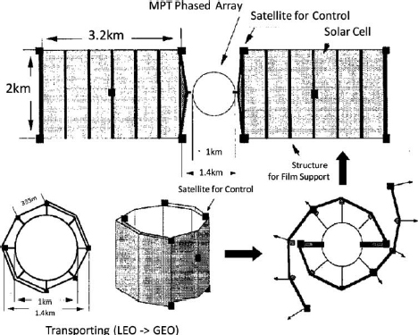
They also designed a new SPS which is called tethered-SPS [SAS 04]. An artist’s conception of the tethered-SPS is shown in Figure 4.62. The system consists of a large power generation/transmission panel suspended by multitether wires from a bus system above the panel. The attitude is automatically stabilized by the gravity gradient force in the tether configuration without any active attitude control. The power generation/transmission panel consists of perfectly equivalent modules, which significantly contribute to the low-cost production, testing and quality assurance. For the simplest configuration of the power transmission part, the small antenna element and the microwave circuit are integrated as a single entity using an AIA technology. Another innovative feature of the module is the cableless interface realized using a wireless local area network (LAN) system, which leads to reliable deployment, integration and maintenance. The tethered-SPS is an assembly of equivalent miniature tethered-SPS elements. This tethered-SPS is capable of 1.2 GW power transmissions and 0.75 GW average power receptions on the ground. It is composed of a power generation/transmission panel of 2.0 km × 1.9 km suspended by multi-wires deployed from a bus system that is located over 10 km from the power panel. The weights of the panel and the bus system are 18,000 tons and 2,000 tons, respectively. The panel consists of 400 subpanels of 100 m × 95 m with 0.1 m thickness. Each subpanel has 9,500 power generation/transmission modules each with an area of 1 m × 1 m. In each power module, the electric power generated by the solar cells is converted to microwave power and is used for other control units. Therefore, no power line interface exists between the modules. The microwave transmitting antennas are on the lower plane.
Figure 4.62. Artist conception of the tethered-SPS [SAS 04]
Because this system has no mechanism to track the sun for the power generation, the total power efficiency is 36% lower than that for the NASA/DOE reference model or other sun-pointing types of SPS. However, it is noted that the simple concept resolves almost all of the technical difficulties in past SPS models. The absence of any moving structure on a large scale makes this system highly robust and stable. Because no light concentrators are used for the power generation, a large-scale kilometer-sized power generation area is required, but the heat generated in the panel can be released into space without the need for any active thermal control.
There is no wired signal interface between the power modules. The control signal and frequency standard for each module are provided from the bus system by the wireless LAN. The tethered subpanel is composed of a 100 m × 95 m subpanel suspended by four wires connected to a bus system. The 100 m × 95 m panel with 0.1 m thickness is regarded as a solid panel with a flatness required for the phase control in the microwave power transmission. The subpanel consists of 950 structural unit panels of 10 m × 1 m × 0.1 m.
The structural unit panels are folded in a package of 9.5 m × 10 m × 10 m, which is a unit cargo transported from the ground to the LEO by reusable launch vehicles (RLV). The cargo is transferred to the orbit transfer vehicle (OTV) in a LEO at approximately 500 km and transported to GEO. To avoid the degradation of the solar cells by trapped energetic particles in the radiation belt, the cargo is housed in a radiation-shielded vessel. If we use a 270 MT OTV equipped with an electric propulsion of 240 N thrust, the cargo would be transferred to GEO within two months. The tethered subpanel is then deployed automatically in GEO. After the function test of the tethered subpanel is completed, it is then integrated into the SPS main body. Docking assistant robots that are controlled by the ground control center will be required for the integration. This strategy makes it possible to verify the SPS function during the construction phase from low-power to full-power transmission.
During the SPS research activities performed by JAXA, ISAS and METI, the Society of Japanese Aerospace Companies (SJAC) sometimes also performed SPS studies. A characteristic of the Japanese SPS research is the presence of continuous and parallel activities.
The Basic Plan for Space Policy in Japan was established by the Strategic Headquarters for Space Policy in June 2009. This Basic Plan for Space Policy that was forged at that time was based on the Basic Space Law, which was established in May 2008, and which is Japan’s first basic policy relating to space activities. In the plan, SPS was selected based on nine systems and programs for the use and R&D of space, as follows [BAS 09a, BAS 09b]:
“As a program that corresponds to the following major social needs and goals for the next 10 years, a Space Solar Power Program will be targeted for the promotion of the 5-year development and utilization plan”, and “government will conduct ample studies, then start technology demonstration project in orbit utilizing ‘Kibo’ (Japanese experimental module on International Space Station) or small sized satellites within the next three years to confirm the influence in the atmosphere and system check”.
More than three years have passed from the establishment of the first Basic Plan for Space Policy. During those three years, the Japanese government has changed hands from the Liberal Democratic Party, which had political power for a long time, to the Democratic Party of Japan. Unfortunately, there was less progress in the development of the Space Policy by the Democratic Party of Japan over this three-year period. However, on June 20, 2012, the Japanese government established a new law concerning space development, which is called “Law of partial improvement of the Office of National Space Policy and the Committee on National Space Policy in the Cabinet Office”. In the new law, they declared that Cabinet Office will have jurisdiction over Japanese space development rather than several Ministries, including the Ministry of Education, Culture, Sports, Science and Technology, which has jurisdiction over JAXA, which in turn has jurisdiction over the Japanese space development. They also declared that a new space policy decision commission will be established instead of the old Space Activities Commission which had previously led the Japanese space activities. Seven members of the new space policy decision commission were selected in July 26th, 2012 [BAS 12].
In the new Basic Plan for Space Policy, the targets of Japan’s space development were narrowed down to the following four systems for the utilization of space and three programs for R&D purposes.
Four social infrastructures for expanding the utilization of space and ensuring autonomy are:
Three programs that pursue the possibility of future development and utilization of space are:
The Space Solar Power or SPS Program was again selected as an R&D program for future space development. In the policy, the R&D target is described as follows:
The SPS committee formed by METI was restarted from FY2009 based on the Basic Plan for Space Policy in Japan [FUS 11]. The main objective of the restarted committee is the development of a thin and high-efficiency phased array (see Figures 3.48 and 3.49). This activity is jointly supported by METI and JAXA.