
Wireless technology is one of the greatest inventions in the past century that help free the user and realize the actual benefit of “cablefree” without being attached to a string or cable for connection. The first ever wireless message was a morse code sent over a kilometer distance by the inventor of wireless technology Guglielmo Marconi. Fast forwarding 100+ years now, wireless is an integral part of our life with almost every connected device leveraging wireless technology in one form or the other and thereby making it lot easier for installation and management.
The breakthrough discovery of radio waves in 1880 paves the way for all the wireless communications that are currently being enjoyed by this and will be enjoyed by the future generations. While originally used for transmitting audio signals, the electromagnetic spectrum comprises various radiations such as microwave, infrared, and visible light that were explored further to encode data. The bandwidth and the coverage radius are determined by the selection of the radiation range within the spectrum.
While the electromagnetic spectrum spans across varying ranges, the primary focus of this chapter is on wireless LAN that ranges within 2.4 GHz to 6 GHz.
Basics of Radio Waves and Spectrum

An image depicts wireless spectrum. Radio wave spectrum range from three Kilohertz, Very Large Frequency to three hundred Gigahertz, and Extremely High Frequency.
Wireless spectrum
The radiation travels at the speed of light in the form of sine waves in free space or in any medium. For better understanding, imagine you throwing a pebble into a still water, and you could notice the waves propagating outward in all direction as sine waves from the point where the pebble disturbed the still water. The radiation will travel in a similar manner from the source that generates the waves.

A pictorial representation of Radio wave. It reflects; Frequency, number of wave cycles within a second; Wavelength, distance between peak points; Amplitude, maximum displacement of the wave from its mean position.
Radio wave
By modifying the amplitude (AM) or the frequency (FM) of the waves, data can be encoded and traversed from one point to another using the electromagnetic waves. This forms the basics of wireless communication technology.
Considering the range of spectrum available, there must be some form of regulatory body to regulate the allocation and licensing of the spectrum. The International Telecommunication Union (ITU) Radiocommunication Sector and the US Federal Communications Commission (FCC) took that responsibility to manage and regulate the frequency allocation and transmission methods. FCC grants the spectrum license to any entity by providing the exclusive rights to use the spectrum range for a period of time for a charge. Such licensed range can either be sublicensed or leased to other entities by the parent entity that owns the license but cannot be used by other entities without the consensus from the parent entity. In order to promote and drive innovation, FCC also assigns a range of spectrum as unlicensed which allows any entity to freely use this range without any charge.
Within the radio wave spectrum that spans from 3 KHz to 300 GHz, ITU reserves a range of frequency from radio waves internationally for industrial, scientific, and medical applications. This band is collectively referred to as the ISM band. FCC originally allocated three unlicensed frequency bands from ISM as 900 MHz, 2.4 GHz, and 5 GHz. Around 2020, FCC opens 6 GHz from the midband spectrum for unlicensed use by the public.
The 900 MHz is a narrowband radio frequency primarily used for voice communication. For more details about the ISM band and the regulations, please refer to Article 5 of the ITU Radio Regulations, which is a document defined by ITU to regulate the radiocommunication services.
In the next section, we will further discuss about the unlicensed ISM band and how it is used for wireless LAN communication.
Basics of Wireless LAN Technology
A local area network (LAN) is a private collection of devices sharing the same subnet that either can reside within the same physical location or can span across regions using advanced technologies such as Virtual Extensible LAN (VxLAN) or Network Virtualization using GRE (NVGRE). Traditionally, all the devices within a LAN network are connected through wired Ethernet cable to layer 2 Ethernet switches. Connecting multiple devices to a shared medium raises different types of challenges such as defining a common and globally agreeable frame and header format, media access–specific challenges such as frame collision detection and avoidance, transmission error detection and correction, etc. To address these challenges, the Institute of Electrical and Electronics Engineers (IEEE) formed the 802 LAN/MAN Standards Committee around 1980 to develop and standardize OSI data link layer protocols and standards for LAN networks. IEEE 802.3 is the workgroup created for Ethernet-based LAN network. When the devices within the same LAN network are connected through a wireless medium instead of an Ethernet wired cable, the network is referred to as wireless LAN (WLAN).
Assign the endpoints to the respective wireless channels.
Assign the IP address from the WLAN subnet.
Transmit and receive wireless radio signals between each endpoint within the WLAN.
Connect the endpoints within the WLAN to the wired network.
The endpoints are any device such as laptops, mobile phones, or other smart-connected things that are capable of communicating via WLAN.
Various taskforce and study groups were created under IEEE 802.3 to develop standards for different data rates such as 100 Gb Ethernet, 200 Gb Ethernet, 400 Gb Ethernet, etc. While IEEE primarily focused on developing standards for PHY and MAC layers, IETF created workgroups for upper layer protocols. IETF CAPWAP is one such workgroup chartered to develop upper layer protocols for WLAN.
Wireless LAN Channels
With the evolution of radio technologies and the release of unlicensed ISM bands by FCC, the IEEE 802.11 workgroup was created around 1985 in an attempt to develop and standardize PHY and MAC layer protocols. WLAN leverages unlicensed spectrum bands, and so most of (if not all) the standards are developed around 2.4 GHz and 5 GHz bands.
With the recent release of 6 GHz from the midband as an unlicensed spectrum, new standards are being developed.
2.4 GHz Frequency Channels
Channel | Lower Frequency | Upper Frequency | Mid-frequency |
|---|---|---|---|
1 | 2401 | 2423 | 2412 |
2 | 2406 | 2428 | 2417 |
3 | 2411 | 2433 | 2422 |
4 | 2416 | 2438 | 2427 |
5 | 2421 | 2443 | 2432 |
6 | 2426 | 2448 | 2437 |
7 | 2431 | 2453 | 2442 |
8 | 2436 | 2458 | 2447 |
9 | 2441 | 2463 | 2452 |
10 | 2446 | 2468 | 2547 |
11 | 2451 | 2473 | 2462 |
12 | 2456 | 2478 | 2467 |
13 | 2461 | 2483 | 2472 |
14 | 2473 | 2495 | 2484 |
Each channel within the 2.4 GHz range is 22 MHz in width and 5 MHz apart between each channel with some overlap between the channels with an exception for Channel 14. For example, Channel 1 ranges from a lower frequency of 2.401 GHz to a higher frequency of 2.423 GHz with a mid-frequency of 2.412 GHz, while Channel 2 ranges from a lower frequency of 2.406 GHz to a higher frequency of 2.428 GHz with a mid-frequency of 2.417 GHz. There is a significant overlap between these channels, and the use of such overlapping channels may cause network slowness and packet loss due to channel interference. To avoid any performance degradation, the best practice is to use non-overlapping channels. It could be noted from Table 4-1 that the upper frequency of Channel 1 is 2.423 GHz, while the lower frequency of Channel 5 is 2.421 GHz. So, Channel 1 overlaps with Channels 2, 3, 4, and 5. The lower frequency of Channel 6 is 2.426 GHz which does not overlap with Channel 1. Selecting such non-overlapping channels during the WLAN deployment will help avoid any channel interference and so improve the performance.
In the 2.4 GHz band, Channels 12 and 13 are allowed to be used only in low-power mode. Channel 14 is not legally allowed to be used in the North America domain. This is to avoid interfering with the next licensed band that is used for satellite communication. So ideally, there are 11 channels available for use in 2.4 GHz.
5 GHz Frequency Band
Name | Frequency Range (GHz) | Bandwidth (MHz) |
|---|---|---|
U-NII-1 | 5.150–5.250 | 100 |
U-NII-2A | 5.250–5.350 | 100 |
U-NII-2B | 5.350–5.470 | 120 |
U-NII-2C | 5.470–5.725 | 255 |
U-NII-3 | 5.725–5.825 | 100 |
Each U-NII band within the 5 GHz band comprises multiple channels where each channel is of 20 MHz bandwidth. Multiple adjacent channels (more specifically 2, 4, or 8 adjacent channels) can be combined to form wider channels with 40 MHz, 80 MHz, and 160 MHz bandwidth, respectively. For example, Channel 36 from U-NII-1 has a bandwidth of 20 MHz with lower frequency of 5.170 GHz and upper frequency of 5.170 GHz. Channel 40 from U-NII-1 has a bandwidth of 20 MHz with lower frequency of 5.190 GHz and upper frequency of 5.210 GHz. Channel 38 combines Channels 36 and 40 to increase the bandwidth to 40 MHz with lower frequency of 5.170 GHz and upper frequency of 5.210 GHz. Unlike the 2.4 GHz band, 5 GHz can be used with a total of 25 non-overlapping channels.
The U-NII-1 frequency band is to be used strictly for indoor purposes. The frequency band defined as U-NII-2B is currently not available for unlicensed use.
On the one hand, the lower frequency travels further but comprises smaller bandwidth, while on the other hand, the higher frequency comprises higher bandwidth but doesn’t travel further. While both 2.4 GHz and 5 GHz are globally unlicensed, the speed and coverage range varies for both the bands. 2.4 GHz is primarily targeted to provide higher coverage with lower bandwidth, while 5 GHz is used to provide higher bandwidth.
Wireless LAN Topologies
Basic Service Set (BSS)
Extended Service Set (ESS)
Mesh Basic Service Set (MBSS)
Basic Service Set

An model illustrates Basic Service Set, that depicts wireless network endpoints and wireless access points. It has Internet, router and user device
Basic Service Set
The network identifier is commonly referred to as the Service Set Identifier (SSID), which is a natural language label. This topology is referred to as an autonomous topology as they are stand-alone and fully functional service sets where the access point will allow the communication between the endpoints and beyond the wireless network. All the connected endpoints and the access point within the same BSS will use a single wireless LAN channel for sending and receiving radio signals.
Extended Service Set

An image illustrates Extended Service Set. It has multiple Basic service set connected with wired network
Extended Service Set
This topology leverages a common distribution system such as a wireless LAN controller that manages all the wireless AP configuration and inter-BSS communication between endpoints in different BSS. All the wireless APs within the ESS will advertise the same SSID, thereby allowing any wireless endpoint to seamlessly roam from one BSS to another BSS without service interruptions.
In the ESS, we mentioned that all the wireless APs will advertise the same SSID which is the network name. To differentiate the wireless access point to which the endpoint is connected, each wireless AP will also advertise BSSID which is unique for each access point. BSSID is the MAC address of the advertising wireless AP.
Mesh Basic Service Set
The Mesh Basic Service Set (MBSS) forms a group of mesh stations sharing the same mesh profile to create a much larger wireless network (such as a community). Each AP within the mesh network will use radio antennas for both connecting the endpoints and backhauling the traffic toward other APs within the same mesh network.
Wireless LAN Encryption Protocols
Wired Equivalent Privacy (WEP)
Wi-Fi Protected Access (WPA)
Wi-Fi Protected Access 2 (WPA2)
Wi-Fi Protected Access 3 (WPA3)
The WEP protocol, originally standardized around 1999, uses a key value of size 40 bits along with a fixed-size initialization vector (IV) to generate a 64- or 128-bit-sized seed value that is used to encrypt the data before forwarding. The key used can be easily cracked, and so this approach is not very secured. The Wi-Fi Alliance officially decrypted this protocol around 2004, and it is not commonly used in the recent deployments.
The WPA protocol, originally standardized around 2003, leverages a much stronger mechanism referred to as the Temporal Key Integrity Protocol (TKIP) and Message Integrity Check (MIC). While MIC helps prevent man-in-the-middle attacks, TKIP dynamically changes the keys used to encrypt the data, thereby making it more challenging for the malicious users to decrypt the data exchanged over the wireless medium. The WPA can be implemented in two different modes. The personal mode, also referred to as WPA-PSK, leverages the preshared key to generate the encryption key, while the enterprise mode, also referred to as WPA-EAP, leverages an external authentication server to generate the encryption key based on the EAP parameters.
The WPA2 protocol, originally standardized around 2006, is far more advanced compared to the previous version WPA. WPA2 replaces TKIP with the Advanced Encryption Standard (AES) and Counter Mode Cipher Block Chaining Message Authentication Code Protocol (CCMP) to generate the encryption keys. Based on the combination of the preshared key associated to the wireless LAN network, the unique NONCE generated by the client, and the access point, a dynamic encryption key is generated which will be changed periodically to make it difficult for any malicious users to decrypt.
The WPA3 protocol is the most recent one and primarily being positioned for Wi-Fi 6. WPA3 leverages the Simultaneous Authentication of Equals (SAE)–based key establishment mechanism.
Setting Up 802.11 Radio Tap
Managed mode
Monitor mode
In the managed mode, the antenna will register with the base station as a traditional endpoint and consume the radio frames that are received from the respective channel allocated to the client. In the monitor mode, the antenna will be programmed to sniff any radio frames in the air.
In this section, we will discuss different options available for different operating systems to capture the wireless frames with radio headers for analysis.
Wireless Capture Using Native Wireshark Tool
This option works for all the operating systems that natively support the Wireshark tool. While this section was explained with captures from macOS, other operating systems support the same options.

An image of interface illustrates Wireshark capture options. It has capture tab with Capture options
Wireshark capture options

An image of dialogue box depicts Default capture options. Dialogue box has Input tab; wifi interface with Ethernet link layer header
Default capture options
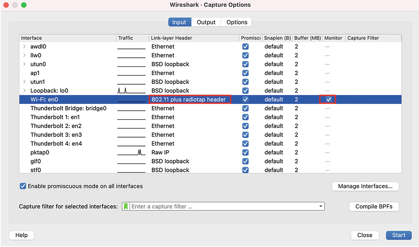
An image illustrates monitor capture option. Dialogue box input tab has; interface, Wi Fi and link layer, Eight Zero Two point one one plus radiotap header
Monitor capture option
By starting the capture, we now can see that the tool captures frames with radio headers for analysis.
When the radio antenna in the laptop is changed to be in monitor mode, it will capture all the radio frames in the air and not just the one targeted to the laptop. For security purposes, this feature may be disabled by the administrators.
Wireless Capture Using AirPort Utility
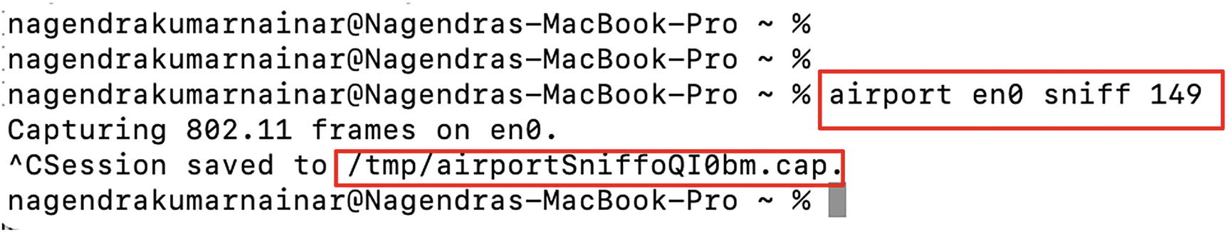
An image of commands depicts Airports Utility commands. It highlights sniffer command; airport en zero sniff one four nine.
AirPort Utility commands
The CLI format as shown earlier will allow us to instruct the interface (en0 in this example) from where the radio frames must be captured and the channel (149 in this example) as well.
Wireless Capture Using Diagnostic Tool

An image depicts Wireless Diagnostic Tool. It has options; Open Wireless Diagnostic which further highlights B S S I D, channel frequency and country code
Wireless Diagnostic Tool

An image of a dialogue box depicts sniffer configuration diagnose. It has, channel number; width in hertz selection option and a start button
Diagnostic sniffer configuration
When the radio antenna in the laptop is programmed to be in monitor mode using any of the preceding options, the end-user device, such as a laptop, will stop working in managed mode and go offline, losing any Internet connectivity. Once the capture is stopped, the device doesn’t move to managed mode and connect to the network by default. It may need to be done manually.
Wireless Operational Aspects – Packet Capture and Analysis
In this section, we will discuss various operational aspects of a wireless LAN network along with packet capture and analysis.
802.11 Frame Types and Format
Management frame
Control frame
Data frame

An image indicates I E E E 8 0 2 point 1 1 frames format. It has; Frame control; Duration; Receiver; destination; Transmitter address; Sequence Control; Source address; B S S I D; Frame Body; F C S. Frame control further divided in eleven parts.
IEEE 802.11 frame format
The Frame Control Field is of 2-byte size that in turn encompasses subfields for control information and additional flags. The Version is a 2-bit-sized subfield with a value set to 00. The Frame Type and the Sub-Type subfields define the type of the frame. The To DS flag identifies the direction of the frame if it is going to the access point. The From DS flag identifies if the frame is coming from the access point. For any broadcast frames, both the To DS and From DS flags will be set to 0. The More Frag flag indicates that additional fragments of the frame will follow. The Retry flag indicates that this frame is a retransmission of a previous frame. The Power Mgmt flag indicates that the sender is in power-save mode. The Protected flag indicates that the frame is encrypted.
The Duration is of 2-byte size that serves two purposes based on the type of the frame. This field can be used to carry the Association ID when the frame type is control frames and the same field is used to carry time duration when the frame type is management or data. The duration value defined is the airtime reserved by the sending antenna for an acknowledgment before resending the frame.
The Address 1 (Receiver) is set to the MAC address of the receiver of the frame. The Address 2 (Destination) is set to the MAC address of the ultimate destination of the frame that will further process the upper layer payloads. The Address 3 (Transmitter) is set to the MAC address of the transmitting radio antenna. The Address 4 (Source) is set to the MAC address of the ultimate source that originated the frame.
The BSSID (as defined in the earlier section) is set to the MAC address of the access point.

An image of 8 0 2 point 1 1 management frame. It has commands; Frame Control Field colon Zero X Eight Zero Zero Zero and sub command Flags colon Zero X Zero Zero
802.11 management frame
The 802.11 radio information field includes the radio-specific details such as the spectrum band (2.4 GHz vs. 5 GHz), the channel on which the frame is captured, the data rate for this channel, the signal-to-noise ratio (SNR), signal strength, etc. This information is essential to troubleshoot any wireless failures or slowness-specific issues. For example, a minimum of 20 dB SNR value is recommended for the wireless network to function properly, and a value of around 40 dB is considered excellent.

An image of commands depicts Radiotap metadata. It has commands; Present Flags; Flags colon Zero X one two; Channel flags colon Zero x Zero one four Zero comma Orthogonal Frequency Division Multiplexing comma five G H z Spectrum and Vendor namespace.
Radiotap metadata
The radiotap header shown in Figure 4-13 is actually not part of the frame. But this is a metadata container added by the radiotap module while capturing the wireless frame. This metadata container includes frame- and channel-specific details such as the frequency, the frame timestamp, antenna signal, etc.
Wireless Network Discovery

An image of 8 0 2 point 1 1 S S I D broadcast illustrates two access points with different S S I Ds
802.11 SSID broadcast

An image of program depicts 8 0 2 point 1 1 beacon frame. It has frames with; S S I D information; Supported Data rates; Robust Security Network Information
802.11 beacon frame
The SSID parameter will carry the SSID details configured for the advertising wireless access point. The frequency band and the channel information along with the SSID will be used by the endpoint while sending the request to join the network. The beacon also includes all the data rates supported by the access point. Depending on the type of the 802.11 standard configured on the access point, different data rates will be advertised. One of the data rates will be mandatory for the endpoint and the access point to negotiate and support the onboarding.
The Robust Security Network (RSN) parameter is an optional field included in the beacons advertising the encryption and authentication capabilities. Depending on the type of the group Cipher Suite, the respective keys will be negotiated to encrypt the payload. The Authentication Key Management (AKM) field is used to identify if the initial authentication is based on a preshared key or using the 802.1X method. In the preceding beacon frame, the AKM is set to PSK (Phase Shift Keying), which indicates that a preshared key is required to authenticate during the onboarding process.
By continuously broadcasting the SSID, the network is vulnerable for malicious users to try hacking the network. For security purposes, most of the wireless access point vendors support the configuration option to disable the SSID broadcast. In such case, the user endpoint stations are required to be manually configured with the wireless network details.
Some of the useful filtering mechanisms to filter all the beacons or specific fields within the beacons are as follows.
For detailed filtering options specific to 802.11 frames, please visit www.wireshark.org/docs/dfref/w/wlan.html.
Wireless LAN Endpoint Onboarding
By simply scanning the wireless channels, any endpoint station will be able to identify all the available wireless LAN networks based on the received beacons. In this section, we will discuss the registration and user onboarding process to join the network.

An image highlights the registration process of wireless connection between Access point, router and End point, Laptop. It consists of steps; Probe Request; Authentication Request; Association Request; E A P O L. Access point sends Beacon frames with S S I D on regular interval.
Registration process
In the following section, we will split the process into different phases and explain the same using 802.11 frame captures.
Probing Phase

An image of program depicts Probe Request Frame. It has command; Frame Control Field colon Zero x four Zero Zero Zero.
Probe Request frame
The subtype of this frame is set to Probe Request, and this frame is sent from the endpoint station to the wireless access point. The source and the transmitter address are the same and are set to the sending endpoint station. The destination and the transmitter address are set to broadcast. The SSID is set to the tag of the wireless LAN network to which the endpoint is intending to join. While the SSID is set to the relevant name, the BSSID is set to broadcast as this frame is a broadcast and is not targeted to any specific wireless access point.

An image of program depicts Probe Response frame. It has commands; Capabilities Information colon zero x one one one one; Tag colon R S N Information highlighted with red color mark
Probe Response frame
The Probe Response sent from the wireless access point is a unicast frame, and so the destination and the receiver address will be set to the MAC address of the endpoint station. The Capabilities Information field will include different types of capabilities of the access point. The ESS bit is set to 1 when the access point is configured to be part of the infrastructure network and not as an ad hoc network. The Privacy bit is set to 1 that mandates the use of security protocols to encrypt the data exchanged between the endpoint station and the access point.
It also includes the Robust Security Network information that instructs the type of authentication and encryption supported by the access point for secured onboarding and data privacy purposes.
Authentication Phase

An image depicts 8 0 2 point 1 1 Authentication frame. It has Commands; I E E E 8 0 2 point one one Authentication comma Flags with sub command Frame Control Field colon Zero x b Zero Zero Zero, and Wireless Management Frame.
802.11 Authentication frame
This management frame is unicasted from the endpoint station to the wireless access point. The Authentication Algorithm field is set to a value of 0 which indicates that the algorithm is Open System. The Status code is set to “Successful” in this frame.
While the figure and most of the standards indicate that the authentication request and response frames are exchanged, there is just a subtype that indicates the frame as an Authentication frame. The Authentication SEQ of 1 is considered as the request and 2 as the response. Both the frames will have the Status code set to “Successful.”
Association Phase

An image depicts 8 0 2 point 1 1 Association Request frame. It comprises fixed parameters, tags and supported channel commands.
802.11 Association Request frame
The endpoint will unicast this management frame and will include only the capabilities that match the one advertised by the access point to which the endpoint is associating. In addition, the endpoint will include all the supported channels from the spectrum to let the access point choose the one supported.

An image of a program illustrates 802.11 Association Response frame. It comprises fixed parameters, tagged parameters, primary channel: 149 and tag commands.
802.11 Association Response frame
The Status code in this frame is set to “Successful,” indicating the successful association of the endpoint to the wireless LAN network. The wireless access point will include the channel details to which the endpoint is associated. In the preceding example, the primary channel is marked as 149, which is of 5.745 GHz frequency with a width of 20 MHz.
802.1X Exchange Phase
Once the endpoint station is associated, a four-way handshake is used to generate and exchange the relevant set of keys to encrypt the data exchanged between the devices over the wireless medium. The first important key is known as the Pairwise Master Key (PMK) that plays a vital role in generating the encryption key. When the mode is set to WPA or WPA2 personal (that uses PSK), the PMK is the passphrase configured with the wireless network.
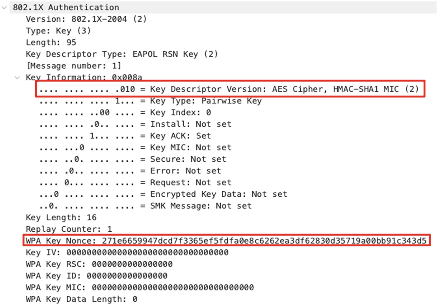
An image of a program illustrates first Extensible Authentication Protocol over L A N frame. It comprises commands, key descriptor version and W P A key nonce, highlighted in red color.
First EAPOL frame
The access point will generate a locally unique NONCE (referred to as aNONCE) value and include the same in the first EAPOL frame. The endpoint will generate a locally unique NONCE value (referred to as sNONCE) and use a combination of aNONCE, sNONCE, access point MAC address, and endpoint MAC address to generate a Pairwise Transient Key (PTK). This key is used to encrypt all the unicast traffic.

An image illustrates a program of second Extensible Authentication Protocol over L A N frame. It comprises 802.1 authentication, key information: 0 x 010 a, W P A key commands.
Second EAPOL frame
As shown in Figure 4-23, the End point will include the sNONCE value that can be used by the access point to generate the PTK to encrypt the unicast traffic. The endpoint also includes the MIC value that can be used by the access point to validate the integrity of the incoming EAPOL frame.

An image illustrates a program of Third Extensible Authentication Protocol over L A N frame. It comprises 802.1X authentication, key descriptor type and W P A keys commands.
Third EAPOL frame
The “Install” flag in Key Information is set to 1 that instructs the endpoint to install and use the PTK. The access point also generates a Groupwise Temporal Key (GTK) that is used to encrypt all the broadcast and multicast traffic. This key is normally shared by multiple devices associated to the same access point. The access point will generate this GTK, encrypt it with PTK, and send it over the third EAPOL frame.
The final EAPOL frame is sent as an acknowledgment by the endpoint station to the access point. The endpoint is now ready to send and receive wireless data traffic over the channel assigned.
Wireless LAN Data Exchange
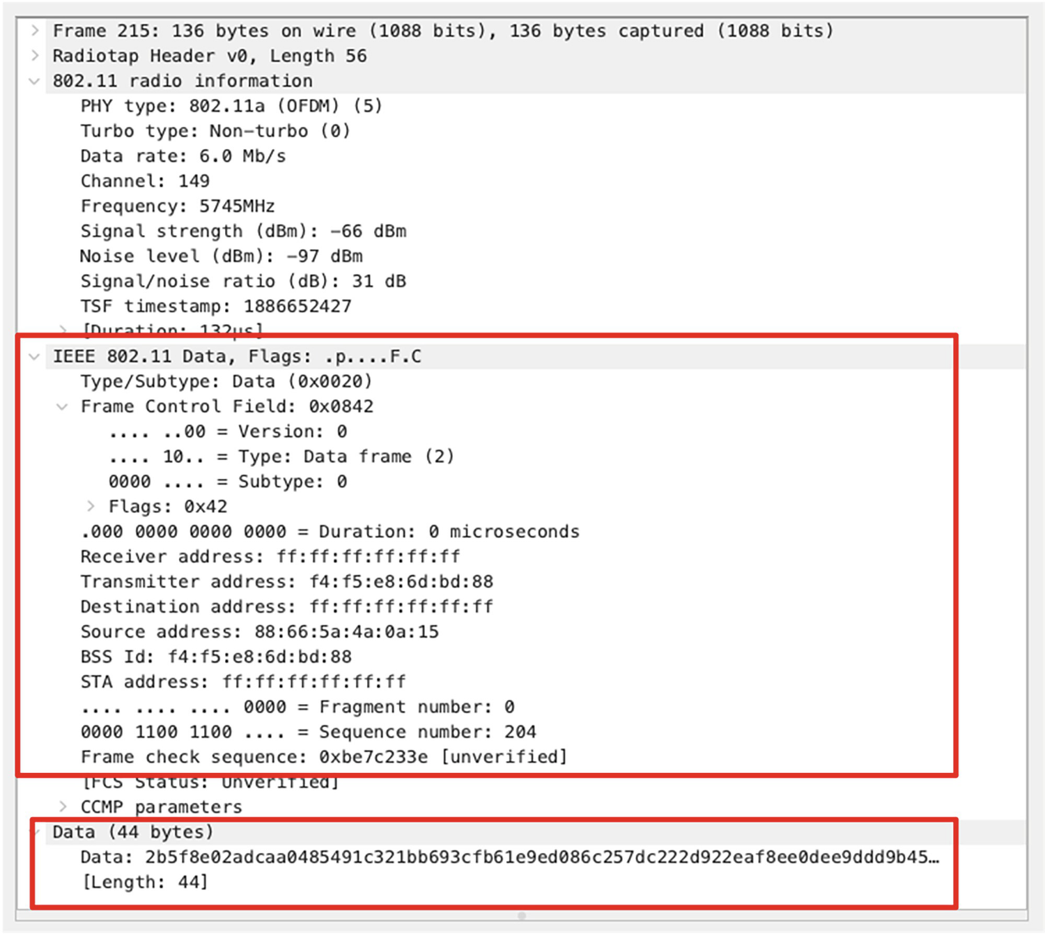
An image illustrates program for 802.11 encrypted data frame. Commands from I E E E 802.1 Data, Flags to Frame check sequence and Data (44 bytes) to [Length:44] is highlighted in red.
802.11 encrypted data frame
The Frame 215 shown in Figure 4-25 is an 802.11 Data frame broadcasted from the access point to all the endpoints in the WLAN network. It could be noted that the upper layer payload encapsulated by the 802.11 header is not plain text, making it hard for analysis.
Decrypting 802.11 Data Frame Payload
In order to decrypt the 802.11 Data frames in Wireshark, we need the encryption keys that are used by the access point and the endpoint to encrypt the payload.
Generating the WPA-PSK Key
To generate the WPA-PSK key, we need the SSID and the passphrase associated to the SSID. There are different tools that can be used to generate the WPA-PSK key. One simple option is to use the WPA PSK (Raw Key) Generator tool available in the Wireshark web page: www.wireshark.org/tools/wpa-psk.html.
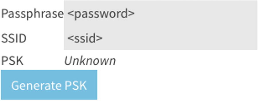
An image illustrates key generator tool program that comprises passphrase, S S I D, P S K and generate P S K.
Key generator tool

An image illustrates program displaying Wireshark decryption key configuration. Command Line Number 215 is highlighted in blue color. It indicates selected feature, Protocol preferences, I E E E 802.11 wireless L A N and open I E E E 802.11 wireless L A N preference.
Wireshark decryption key configuration

An image illustrates Feeding the Wi-Fi Protected Access Pre-Shared Key. It indicates steps 1) click the Add button, 2) Select W P A P S K option and 3) Paste the key generated by the tool.
Feeding the WPA-PSK key

An image illustrates 802.11 decrypted data frame. The commands are highlighted in red from I E E E 802.11 Data to Frame check sequence and Logical link control to Target I P address: 192.168.1.1.
802.11 decrypted data frame
During the time of this chapter authoring, decryption support for WPA3 is a work under progress. More support will be available in the future, which is currently outside the scope of this chapter.
Wireless LAN Statistics Using Wireshark

An image illustrates wireless L A N (W L A N) statistics options. It displays a menu bar highlighted in red that includes file name, Wireshark and options: File, Edit, View, Go, Analyze, Statistics, Telephony, Wireless, Tools and Help. Under Wireless option, W L A N traffic option is highlighted.
WLAN statistics options

An image illustrates wireless L A N (W L A N) statistics output. It includes details for categories: B S S I D, channel, S S I D, percent Packets, percent retry, beacons, data pkts, auths, and other.
WLAN statistics output
Additional statistics of WLAN traffic on a per-MAC address basis is also available in the same statistics window. By clicking the respective SSID/BSSID tab, we will be able to analyze the percentage of frames sent by each device on a per-MAC basis.
Summary
In this chapter, we discussed about the basics of the wireless spectrum along with the definitions of different radio spectrum characteristics and how they help us realize the cablefree world. We further discussed about different licensed and unlicensed bands, channel ranges for each of the bands, and how they can be used for wireless LAN deployments. We also discussed about different deployment topologies.
We further looked deep into capturing and analyzing 802.11 frames over the wireless medium. We discussed about different configuration options to set the radiotap in different operating systems and how to further dissect the fields. We discussed about different wireless security protocols and how they encrypt the data frames and also the options available in Wireshark to decrypt for analysis purposes.
References for This Chapter
IEEE 802.11: www.ieee802.org/11/
FCC 2.4 GHz: https://transition.fcc.gov/Bureaus/Engineering_Technology/Orders/2000/fcc00312.pdf
WPA3 Specification: www.wi-fi.org/download.php?file=/sites/default/files/private/WPA3_Specification_v3.0.pdf
Wireless LAN Display Filters: www.wireshark.org/docs/dfref/w/wlan.html
WPA-PSK Key Generator Tool: www.wireshark.org/tools/wpa-psk.html