
R E P R I N T 8
![]()
packet Field and Bitfield Allocation Order
by Ralph Duncan
Abstract
C and C -based languages give implementations substantial freedom in choosing schemes for bit and byte allocation. The ensuing variability can make it difficult to port programs that depend on particular structure and bit-field layouts. With these problems in mind, packetC prescribes that implementations use big endian byte allocation order and little endian bit allocation order. This paper reviews the related issues of structure field, byte and bit allocation order and describes an algorithmic approach for compensating when the implementation executes on a processor that uses little endian byte allocation order.
Categories and Subject Descriptors D.3.3 [Programming Languages]: Language Constructs and Features — data types and structures
General Terms Languages.
Keywords programming languages; packetC, endianness, allocation order, bit-fields, network processing
1. Introduction
There are many uncertainties with C bitfield implementation, including
- Alignment.
- Packing behavior.
- Container types.
- Straddling.
- Endianness.
The problems are significant enough to have spurred attempts to create separate bitfield ABIs; see Richard Hoga-boom, “A generic API bit manipulation in C,” http://www.embedded.com/1999/9907/9907feat2.htm.
The problem of bit endianness within a collection of bitfields is usually handled in one of three ways:
- Using shifting and masking operations that reflect endianness.
- Using #ifdef statements to compile different field declaration order for big and little-endian scenarios.
- Defining a collection of macros to produce the de sired bit patterns.
Linux seems to have been especially bedeviled by bitfield endianness problems. For further reading, see:
- “Linux: New firewall stack in development” for an example of this kind of problem, http://kerneltrap.org/node/7462.
- For an example of handling the problem with many macros, see http://www.ussg.iu.edu/hypermail/linux/kernel/0211.0/0927.html.
2. Field Declaration Order
It is desirable to declare structures or descriptors in a way that naturally map to diagrams of well-known network protocols? layouts. Thus, packetC maps structure or descriptor fields to memory by mapping from first-to-last field declared to the lowest-to-highest address. A packetC bitfield container (not an individual bitfield) behaves as a field for this purpose. Thus, if field Fj is declared before field Fk, it will reside at a lower-numbered address.
Rationale: the primary use of our structures/descriptors will be to describe fields in various network protocols (e.g., TCP, IPv4 headers). These fields are transmitted and stored in network order (big-endian order). Diagrams of these headers and protocols typically show low to high byte addresses running from left to right and top to bottom. It will be intuitive to make our source code protocols match these layouts. The example below shows how bytes 13-16 of a TCP header are defined in packetC.
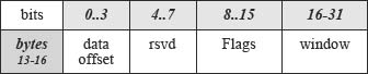
Figure 1. Fragment of a TCP header (bytes 13-16). Copyright Cloud-Shield Technologies, 2011.
Theheader struct declarations in packetC source code match the way people ordinarily represent and think about well-known headers, etc. Thus, our key rule is
As structure or descriptor fields are encountered in the source code from top to bottom, they are mapped from LSB to MSB.
A packetC implementation assigns the short containing the three bit fields to a lower address than the short containing the ‘window’ field, since the bit fields were declared earlier in the source code.
3. Byte Allocation Order within a Field
3.1 Within a Field Other than a Bitfield Container
The network protocols in a packet are stored in network order (most significant numerical part in lowest-numbered address).
User arithmetic or logical operations on a field will be endian convention independent when they operate on entire variables of type short or int.
3.2 Within a Bitfield Container
Bitfield collections (containers) that are stored in multiple bytes cannot simply have their bytes swapped, too, because that would disconnect bits that need to be stored contiguously for the shift and masking instructions that isolate individual fields. Consider the example that follows and recall that little-endian depictions usually:
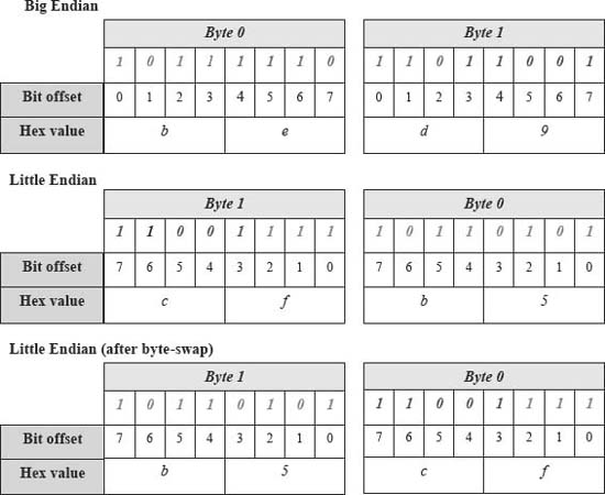
Figure 2. Bitfields, endianness and byte-swapping. Copyright CloudShield Technologies, 2011.
- Show high-to-low numbered bytes from left to right,
- Show high-to-low numbered bits from left to right,
- Display hexadecimal values for 4-bit values without regard for bit order (i.e., if bits 7:4 are 1010, ‘a’ is shown, not 5).
In the subsequent example figures (e.g., Figure 2), the bitfield declarations are coded with colors and font attributes to match storage bits to individual bitfields.
    structs {

      bits short {

              first   :3; // bold & italics

              second  :8; // italics

              third   :5; // bold

      } con; // container name

    }

    s.con.first = 5; s.con.second = 0xf6;

    s. con. third = 0x19;


// C displays the hex values shown in Fig. 2.

// from left to right when displaying an

// equivalent struct.
Note that after a byte-swap on a little-Endian machine, the bits for the bitfield, second, (shown as green values) will no longer be contiguous. Thus, the shift logic that can be used to isolate individual fields on a big-endian machine will not deliver the correct results when used with this bit pattern.
Instead of applying byte swapping to fields that are bitfield containers, it is more useful to treat all bitfields, whether multi-byte or not, with a strategy that addresses differences in bit-order on big and little-endian machines. This strategy is described in the next section.
4. Bit Allocation Order Within a Bitfield
4.1 Overview
First, the bit endianness problem for bitfields does not arise from packet bit transmission/reception order. Although network byte order is big-endian, the prescribed bit arrival order at the physical layer can be little endian, i.e., the least significant bits can have a lower wire address (arrive first). For example, this is the case with Ethernet protocols. However, hardware (e.g., NICs) converts this to the bit endianness expected by the system CPU(s). (For more details see the article below).
“Byte and Bit Order Dissection” by K. He, http://www.linuxjournal.com/article/6788, especially the portion starting at section “Endianness of Network Protocols.”
However, we do have a problem at the bitfield storage level. Big-endian and little-endian platforms will store the individual bits in a different order. The following problems with accessing bitfields can be identified:
- Compiler delivering the correct value for field selection syntax.
- User obtaining correct results from explicit shifting or masking operations.
- User understanding displays for entire bitfield collection (e.g., the containing storage unit).
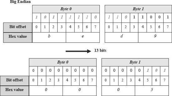
Figure 3. Big endian result of >> 13 operation. Copyright CloudShield Technologies, 2011.
The example recasts the packetC example from section 3.2 into C.
    struct{

        unsigned short  first      :3;

        unsigned short  second     :8;

        unsigned short  third      :5;

    } s;

    s.first = 5; s.second = 0xf6;

    s.third = 0x19;
A gcc compiler will pack this into a short on 32-bit big-endian machines (Sun, HP, AIX) and 32-bit little-Endian machines (X86, DEC Alpha).
On a big-endian machine, this structure is stored in a way that would match network order protocols. A user who equates the structure to short and displays it in hexadecimal would see the value ‘xbed9.’ As shown in Figure 3, the user (and the compiler) can obtain the value of the first field with an intuitive operation, using a C “>> 13” operation.
However, observe in Figure 4 what happens when the user tries to get the first field via ‘>>’ 13” on a little-endian machine.
A little-endian host will report the pre-shifted value as 0xcfb5 and the value after shifting as 0x6 (the three most significant bits of the third field). Note, however, that the construct “s.first” yields the same results with a gcc compiler on big-endian and little-endian machines. The compiler's emitted code reflects whether it is on a big or little-endian machine but the user assumptions above do not take that into account.
4.3 Solution 1 – Alternative Declaration Order
One approach is to selectively declare reversed bitfield order on big vs. little-endian platforms. Consider a simplified example from the Linux kernel (taken from http://www.linuxjournal.com/article/6788).
       struct iphdr {

#ifdef (__LITTLE_ENDIAN_BITFIELD)

        __u8          ihl:4;

                      version:4;

#else

        __u8          version:4;

                      ihl:4;

#endif
Declaring bitfields in the opposite order for a little-endian machine lets source code use the same shifting code with either endianness, since the reversed declaration order compensates for the reverse bit ordering on the two types of machines. This solution allows users to directly obtain bit field values with shifting and masking code.
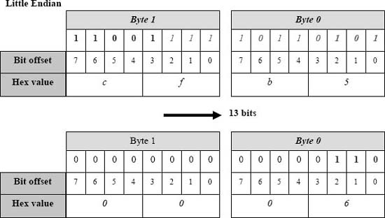
Figure 4. Little endian result of >> 13 operation. Copyright CloudShield Technologies, 2011.
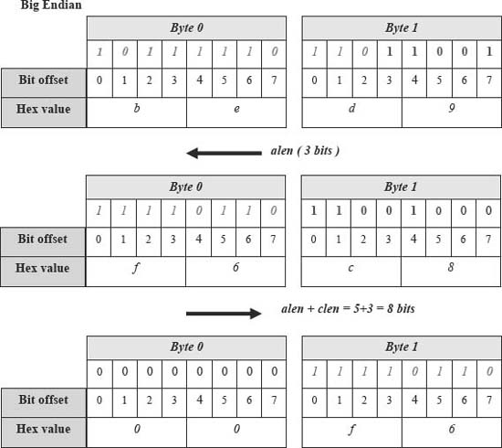
Figure 5. Big endian behavior with the shifting algorithm. Copyright CloudShield Technologies, 2011.
4.4 Solution 2 – Macro Definitions
A set of macros is sometimes used to provide portable bitfield definitions. The following example of this approach shows how unwieldy it can be:
http://www.ussg.iu.edu/hypermail/linux/kernel/0211.0/0927.html.
4.5 Solution 3 – Alternative Algorithms
The third alternative is to commit to a single byte/bit allocation order scheme and require compliant compilers to compensate on machines with a different underlying representation schemes. For operands that involve an integral number of bytes compensation takes the form of swapping bytes. However, to work with bitfields that cross byte boundaries compensation requires the compiler to use a different algorithm (i.e. emit different code sequences) to isolate the bitfield value.
Consider the following algorithmic approach. Any bitfield, b, within a packetC bitfield container can be described by a tuple (alen, blen, clen), where:
- alen is the length in bits of all bitfields in the container declared before b.
- blen is the length in bits of bitfield b.
- clen is the length of all bitfields in the container declared after b.
Thus, the compiler could use the following source code to obtain the value of b for big and little endian machines.
unsigned short us = *(unsigned short *) &s;

// where ‘s’ is the struct or descriptor.

#ifdef (__BIG_ENDIAN_BITFIELD)

        us <<= alen;

#else

        us <<= clen;

#endif

us >>= alen + clen;
For a big endian machine Figure 5 shows how the variant left bitwise shift yields the correct behavior to get the second field's value in our section 4.2 example (where alen = 3 and clen = 5.
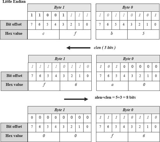
Figure 6. Little endian behavior with the shifting algorithm. Copyright CloudShield Technologies, 2011.
Figure 6 shows the shifting algorithm applied to isolating th e same middle bitfield on a little endian platform.
5. Conclusion
Ultim ately, the packetC language designers converged on requiring a compliant implementation to represent the pack et array (and, therefore, packetC descriptors and structures) with big endian byte allocation order and little endian bit allocation order.
Thus, we gravitated to the third solution (section 4.5):
![]() Vendors and users supply only a single definition of network protocols (which uses big endian byte allocation order and little endian bit allocation order).
Vendors and users supply only a single definition of network protocols (which uses big endian byte allocation order and little endian bit allocation order).
![]() User code is not required to contain platform-specific code that isolates individual bitfields.
User code is not required to contain platform-specific code that isolates individual bitfields.
![]() Compliant packetC compilers are responsible for emitting platform-specific code that manipulates field and bitfield contents on the basis of host machine attributes, when the user references them.
Compliant packetC compilers are responsible for emitting platform-specific code that manipulates field and bitfield contents on the basis of host machine attributes, when the user references them.
We believe this is the simplest, most intuitive solution. Subsequently, CloudShield has used this approach in delivering packetC compilers and an extensive set of network protocol definitions, expressed in packetC.
R. Duncan. “packetC field and bitfield allocation order.” 2010. Printed by permission.