
Nanoenergy Materials
Sources for alternative energy are increasingly necessary given the rapid consumption of nonrenewable energy sources such as fossil fuels. In a similar vein, rapid resource consumption has attributed to the pollution of Earth to near-critical levels. As such, scientists have been employing nanotechnology for alternative and sustainable energy applications. Chapter 10 summarizes the use of nanomaterials for energy applications, with examples including nanomaterials for fuel cells, high-performance batteries, and solar cells.
Keywords
Hydrogen storage; proton-exchange membranes; solar cells
It has long been noted that there is a huge discrepancy between the finite fossil fuels on earth and the unlimited human needs. Traditional fossil energy is facing two main issues concerning its use: energy depletion and environmental pollution. Based on existing reserves and the rate of consumption, oil, coal, and other major energy sources will be depleted in the next few decades to hundreds of years. To make it worse, the use of traditional fossil energy sources has caused increasingly serious environmental pollution. Current global emissions of carbon dioxide each year have gone up to 2.1 million tons, leading to the deterioration of the environment; in the air, carbon dioxide and dust levels have seriously affected people’s health and the natural environment for human survival. The use of fossil fuels is causing an ecological disaster on Earth, with global warming and acid rain posing serious threats to the survival of the Earth’s flora and fauna. Therefore, years ago, researchers and activists called for the development of renewable energy beyond traditional fossil fuels.
Renewable energy sources are numerous, including wind, hydro-energies, as well as geothermal, tidal, and solar energies. Except for solar energy, other energy sources all have obvious regional characteristics.
Solar energy is abundant. It is estimated that energy generated from 40 min of solar radiation from the Earth can meet the 1-year energy requirements of people all around the world. As a clean energy, unlike oil, coal, and other fossil fuels, solar energy will cause no “greenhouse effect” or any environmental pollution. Easy use is another characteristic of solar energy. In comparison with hydro, wind, and other new energy sources, it is not subject to geographical restrictions and its use comes at a low cost. One important way to use solar energy is to develop solar cells that directly convert sunlight into electrical or chemical energy.
Environmental issues are closely related to energy issues. The types of available energy sources and their implementation have a positive or negative impact. Driven by the aforementioned issues, researchers hope to use nanotechnology to solve or alleviate the imminent energy crisis and find sustainable sources of energy for humanity.
Nanotechnology is based on atoms and molecules in manufacturing materials and products. This small to large manufacturing approach requires fewer materials and would cause less pollution. As a result of the miniaturization, nanotechnology products require fewer resources. The objectives of sustainable development are “low consumption, high efficiency,” and lower costs, and these can be achieved. In the foreseeable future, large-scale machinery and equipment that are expensive and wasteful in regard to resources will be phased out with the aim of achieving “zero resource consumption.” Therefore, promoting the use of nanotechnology is an energy-saving activity. Application technology in the development of nanoenergy resources is mainly focused on two key directions: “nanoenergy storage materials and technology” and “nanoenergy-saving technologies.” Because nanoscale energy storage materials are characterized by high activity, large surface area (200–2,000 m2/g), self-assembly (1–3 nm active catalyst), small sizes (10–30 nanostructure), and possible photoelectric effects, most developed countries are actively involved in the development of energy-related nanomaterials, attempting to provide nanofeatured energy density power storage systems that might be significantly superior to the current battery power. In the field of energy storage devices, competitive products being developed include micro-nanofuel cells with a 50-day standby time, high-performance storage appliances, and photochemical batteries two to three times more powerful than conventional lithium batteries. These products all aim at upgrading energy efficiency while reducing energy consumption. New energy-saving applications being developed include heat-exchange systems, energy-saving windows, and solar cells. These products would help the traditional energy-saving technologies reach a higher level.
Research and development of nanoenergy materials include the following main areas.
Nanomicro Fuel Cells
This entails the development of nanocatalytic electrodes (1–3 nm), nanocomposite proton-conducting membranes (1–5 nm channel), and the simulation computation and system miniaturization design. The development of nanocatalytic electrode structures will lead to improved fuel efficiency in fuel cells. Similarly, nanocomposite proton-conducting membranes can enhance fuel cell power density.
High-performance Storage Appliances
High-energy lithium batteries and nanostructured materials and devices have been developed for high-power energy storage (250 W·h/kg). Through the design of nanoelectrode materials and device fabrication technology, materials can have a higher capacity and current discharge rate. High-power (10–20 C) nanostructured electrode materials for high energy storage are based on the use of porous nanostructured (10–50 nm) materials with electrochemical activity such as high-energy electrode materials aiming to significantly increase power density to achieve high-power fast charge and discharge in a few minutes.
Nanothermal Fluid Technology
Nanothermal fluid test equipment, nanothermal fluid numerical simulation technology, nanofluid properties database, and microthermal-exchange system design technology have been established in an effort to guide the industry’s investment in the development of new products and production technology.
Nanocrystal Application Technology
Preparation technology, such as porous nanostructured electrodes, the design technology in redox chromophores and solar dye molecules, and the development of nanocrystal energy-saving electrochromic windows and dye-sensitized solar cells (DSSCs), has been developed to guide the industry’s investment in the mass production of technology development for new products.
10.1 Nanostorage Materials [1]
Nanomaterials are mainly based on hydrogen-based energy storage, and the present research on hydrogen storage materials is focused on the new composition of alloys and the change of microstructures.
Both physical and chemical hydrogen storage require expensive equipment, yet the carbon nanomaterials may bring about an efficient and clean hydrogen storage method. These materials, if used as the hydrogen storage materials in fuel cell vehicles, can effectively prevent air pollution or greenhouse gas emissions.
It has long been known that some solid materials (e.g., metal hydrides) can store a small amount of hydrogen (approximately 1–2% by weight) at room temperature. Some metal hydrides can store more hydrogen (5–7% by weight), but they usually require a temperature of 250°C or higher for hydrogen storage. Nanostorage materials are characterized by high activity, high surface area, and ultrafine particle size (10–30 nm structure). Using the characteristics of nanomaterials to provide an energy storage system of high energy density is the goal.
The larger specific surface area and available surface atoms of nanomaterials result in higher activity (200–2,000 m2/g). Nano-based hydrogen storage materials will be able to provide more adsorption sites for molecular hydrogen. Meanwhile, the hydrogen molecules are more easily dissociated into hydrogen atoms, which, by diffusion, are able to move from the surface of the grain boundaries into the hydrogen storage materials.
For example, carbon nanotubes (CNTs) and nanofibers can also exhibit excellent performance in the absorption of hydrogen at room temperature, acting as a tiny hydrogen-absorbing “sponge.” Materials of this kind have broad application potential and can be used to create hydrogen containers in fuel cell vehicles. To add fuel, a motor vehicle just needs to be driven to a gas station, and hydrogen can be injected into an empty vessel. Calculations show that as long as carbon materials have hydrogen storage of 6.5% by weight, fuel cell vehicles can have practical value (the distance between two stations is set as 500 km or 310 miles).
10.1.1 Features and Objectives of Hydrogen Energy
Hydrogen is one of the most common elements in nature, and there is no depletion of hydrogen resources. Hydrogen has high calorific value; with its combustion product of water, it is emission free in a real sense and is also free from pollution. There are many ways to utilize hydrogen, for example to generate heat via burning or to generate power electrochemically. Hydrogen in storage and in transport can be gas, liquid, solid, or in compound form.
The key technology to achieve hydrogen economy is the development of an inexpensive and highly efficient hydrogen production technology that enables safe and efficient hydrogen storage technologies. Therefore, the priority is to develop new, highly efficient, and safe hydrogen storage materials and hydrogen storage technologies.
Vehicle hydrogen storage systems are designed in accordance with two standards issued, respectively, by the IEA (International Energy Agency) and DOE (US Department of Energy). Here, the IEA standard requires the mass hydrogen storage capacity to be more than 5% and requires the volume capacity to be more than 50 kg (H2)/m3, whereas the DOE requires mass hydrogen storage capacity of more than 6.5% and volume capacity larger than 62 kg (H2)/m3.
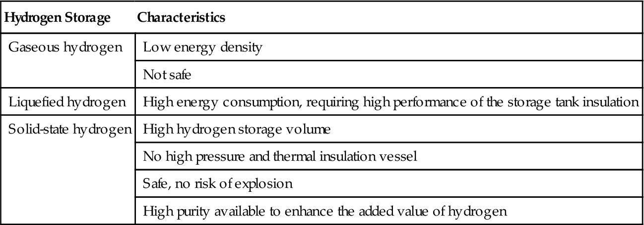
10.1.2 Comparison of Different Hydrogen Storage Methods
The characteristics of various hydrogen storage methods are described in Table 10.1. Obviously, solid-state hydrogen storage has many advantages.
Table 10.1
Comparison of Different Hydrogen Storage Methods
| Hydrogen Storage | Characteristics |
| Gaseous hydrogen | Low energy density |
| Not safe | |
| Liquefied hydrogen | High energy consumption, requiring high performance of the storage tank insulation |
| Solid-state hydrogen | High hydrogen storage volume |
| No high pressure and thermal insulation vessel | |
| Safe, no risk of explosion | |
| High purity available to enhance the added value of hydrogen |
10.1.3 Technology Status of Hydrogen Storage Materials
There are three kinds of hydrogen storage materials: metal hydrides, coordination hydrides, and nanomaterials.
Metal hydrides have the following hydrogen storage characteristics: reversible reactions, hydrogen atom storage structure, solid-state hydrogen storage, safety, reliability, and relatively high-volume density of hydrogen storage. At present, successful developments of metal hydrides as hydrogen storage materials are the RE La–Ni system, titanium–iron system, magnesium system, and titanium/zirconium system.
Hydrogen storage alloy in the RE La–Ni system has a representative, LaNi5, which was first developed by the Philips Laboratories in the Netherlands. It is characterized by its easy activation, moderate and smooth equilibrium pressure, low equilibrium pressure in hydrogen absorption and desorption, good performance of anti-gas poisoning impurities, and is suitable for room temperature operation. By partial replacement of elements, MmNi3.55Co0.75Mn0.47Al0.3 (mixed rare earth, with major components of La, Ce, Pr, Nd) is widely used in nickel–hydrogen batteries.
The titanium–iron system has a representative, TiFe, which was first invented by the US-based Brookhaven National Laboratory. It features a low price, reversible hydrogen storage at room temperature, susceptibility to oxidation, difficult activation, and weak ability in anti-impurity gas poisoning; surface modification is required in the actual use of the alloy.
TiFe alloy is characterized by two hydride phases, namely β-phase (TiFeH1.04) and γ-phase (TiFeH1.95). The hydrogen absorption reactions of the TiFe alloy are:
The magnesium system has a representative, Mg2Ni, which was first reported by the US Brookhaven National Laboratory. It is characterized by high hydrogen storage capacity, abundant resources, low cost, and high temperature of hydrogen release (250–300°C), but its hydrogen release dynamic performance is weak. It can go through mechanical alloying or can be added with TiFe and CaCu5 for ball milling.
Titanium and zirconium materials are intermetallic compounds with the Laves phase structure. The atomic gap in these materials comes from the tetrahedral structure, with more spaces conducive to the adsorption of hydrogen atoms. Typical examples are TiMn1.5H2.5 and Ti0.90Zr0.1Mn1.4V0.2Cr0.4. Characterized by good material activity, they are mainly used for hydrogen storage of hydrogen vehicles and the negative poles of batteries (Ovinic).
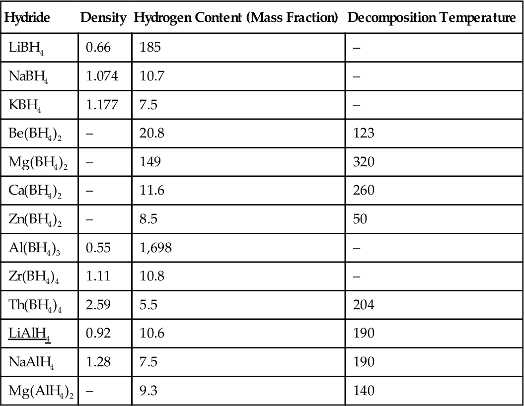
Coordination hydride hydrogen storage material is formed mainly by alkali metals (Li, Na, K) or alkaline earth metals (Mg, Ca) and group III elements (B, Al). It has high hydrogen storage capacity, and it is difficult to restore it to its hydride form (catalytic LiAlH4 in TiCl3 and TiCl4 at 180°C, are able to obtain 5% of the reversible hydrogen storage capacity under a hydrogen pressure of 8 MPa).
The main properties of metal hydride ligands are indicated in Table 10.2.
Table 10.2
Main Properties of Metal Hydride Ligands
| Hydride | Density | Hydrogen Content (Mass Fraction) | Decomposition Temperature |
| LiBH4 | 0.66 | 185 | – |
| NaBH4 | 1.074 | 10.7 | – |
| KBH4 | 1.177 | 7.5 | – |
| Be(BH4)2 | – | 20.8 | 123 |
| Mg(BH4)2 | – | 149 | 320 |
| Ca(BH4)2 | – | 11.6 | 260 |
| Zn(BH4)2 | – | 8.5 | 50 |
| Al(BH4)3 | 0.55 | 1,698 | – |
| Zr(BH4)4 | 1.11 | 10.8 | – |
| Th(BH4)4 | 2.59 | 5.5 | 204 |
| LiAlH4 | 0.92 | 10.6 | 190 |
| NaAlH4 | 1.28 | 7.5 | 190 |
| Mg(AlH4)2 | – | 9.3 | 140 |
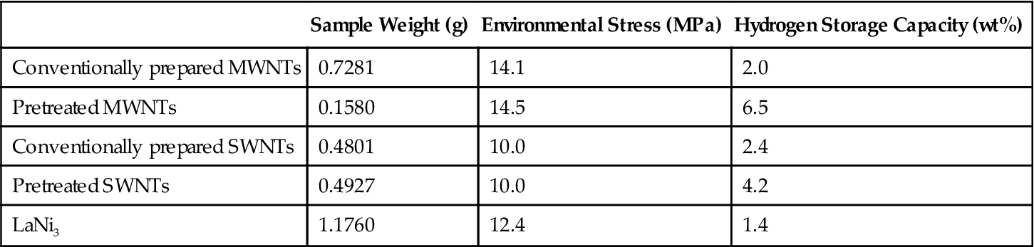
CNTs were discovered in 1991 by Professor Iijima of Japan’s NEC Corporation, but research on the use of CNTs in hydrogen storage was made by the American scholar Dillon, who set a precedent in 1997 [2]. On coke containing 0.1–0.2 wt% single-wall carbon nanotubes (SWNTs), he used the temperature-programmed desorption method to measure the hydrogen adsorption capacity and then found that pure SWNTs have a hydrogen storage capacity of 5–10 wt% at room temperature and a hydrogen pressure of 300 Torr. He also pointed out that hydrogen at the adsorption sites with high temperature is physically adsorbed and the CNTs can have a hydrogen storage capacity 10 times that of activated carbon. The sample size was only 1 mg, and thus the results were obtained through extrapolation; therefore, these results are perhaps unconvincing. Nonetheless, the results are encouraging. As such, there has been much in-depth and extensive research conducted regarding CNTs with regard to their hydrogen storage properties [3].
CNT hydrogen storage can occur in a variety of ways. One is through adsorption of hydrogen storage of CNTs. Table 10.3 shows a comparison of the hydrogen storage capacity of a variety of CNTs in hydrogen absorption.
Table 10.3
Hydrogen Storage Capacities of CNTs and LaNi5 for Comparison (Data Determined by IMR, RT, 10 MPa)
| Sample Weight (g) | Environmental Stress (MPa) | Hydrogen Storage Capacity (wt%) | |
| Conventionally prepared MWNTs | 0.7281 | 14.1 | 2.0 |
| Pretreated MWNTs | 0.1580 | 14.5 | 6.5 |
| Conventionally prepared SWNTs | 0.4801 | 10.0 | 2.4 |
| Pretreated SWNTs | 0.4927 | 10.0 | 4.2 |
| LaNi3 | 1.1760 | 12.4 | 1.4 |
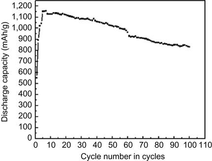
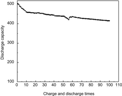
Another mode of hydrogen storage by CNTs is electrochemical hydrogen storage. Research in this area was first reported in 1999 by Nützenadel and associates. Multi-wall carbon nanotubes (MWNTs) after purification had a maximum discharge capacity of 1,157 mAh/g, which is equivalent to 4.1% of hydrogen storage capacity by weight. After 100 cycles of charge–discharge, 70% of its maximum capacity remained. The SWNTs had maximum discharge capacity of 503 mAh/g, which is equivalent to 1.84% of hydrogen storage capacity by weight. After 100 cycles of charge–discharge, 80% of its maximum capacity remained (Figures 10.1 and 10.2).
Hydrogen is the cleanest, most renewable energy and has gained great importance in developed countries over the past decade. China, in recent years, has also invested heavily in research and development in this field. Pilot operations of hydrogen-driven vehicles have been performed in some developed countries, and China is in the process of introducing hydrogen-driven transportation. One of the barriers to the commercialization of hydrogen vehicles is the high cost of hydrogen storage. Taking into account safety and cost, both liquid hydrogen and high-pressure hydrogen gas are not the best choices for the commercialization of hydrogen vehicles. Most hydrogen storage alloy products have a large self-weight, and their life expectancy is also a problem, whereas magnesium-based alloys with a lower self-weight are difficult to store/release hydrogen at room temperature. In addition, reversible hydrogen storage of hydride ligands still needs further development and research. Carbon absorption materials for hydrogen storage have been taken seriously, but their basic research is still not sufficient. Whether it can be put into practical use is still a question. At present, hydrogen storage with nanomaterials has the following problems. There remains a sharp difference in the measured hydrogen storage capacities around the world (from 0.01 up to 67 wt%) without accurate methods for determination. Also, the hydrogen storage mechanism is still unknown. Therefore, the promise of hydrogen energy storage has a long way to go.
10.2 Fuel Cells [5]
10.2.1 Basic Concept
Fuel cells are one of the most important energy technologies in the twenty-first century and are a very promising alternative energy source. At present, the development of fuel cells used for vehicles and fuel cells for portable electronic devices has been classified as one of the top priorities in most developed countries. Fuel cells are a device in which an energy source can be directly converted; chemical energy in the fuel can combine with hydrogen and oxygen into water to produce electricity by using an electrochemical method rather than the burning mode. It is like installing a miniaturized generator in electronic products such as mobile phones, which require an endless fuel supply. In this sense, fuel cells differ from conventional secondary batteries. Therefore, fuel cells are actually power generators that are safe, clean, and characterized by long duration, long lifetime, portability, and cost-effectiveness. In addition, fuel cells can also be used in lighting devices, television sets, refrigerators and motors, and can also be widely used in military supplies. At present, the fuel cell is still in the development stage in the fields of materials and application. Any breakthrough in some key technologies will certainly result in a huge impact on the industry.
The basic principle of fuel cell power generation is based on a chemical reaction of hydrogen and oxygen that results in water, heat, and chemical energy, and the chemical energy can be directly converted into electricity. Specifically, the fuel cell is a “generator” using the reverse reaction of water electrolysis. It is composed of anode, cathode, and an electrolyte panel situated in the middle of the positive and negative electrodes. Initially, the electrolyte plate is formed by the use of electrolyte infiltration of the porous plate and is now being developed into a type that uses solids directly.
Under operating conditions, the negative terminal is supplied with fuel (hydrogen), while the positive terminal is supplied with oxidant (air). Hydrogen is broken down into H+ ions and e− electrons at the negative terminal. Hydrogen ions will enter the electrolyte, while electrons move along the external circuit to the positive terminal. Electricity load is connected to the external circuit. In the cathode, the oxygen in the air and the hydrogen ions in the electrolyte will result in the absorption of electrons entering the cathode to form water. This is precisely the reverse reaction of the water electrolysis process. By taking advantage of this principle, fuel cells in operation can continuously provide electricity to an external power source, hence the name “generator.”
In fact, the fuel cell had been invented before the internal combustion engine was invented in the nineteenth century. In 1839, William Grove made the first primitive model of the fuel cell, which was based on the different redox potentials of H2 and O2 to obtain an available electromotive force. However, there was a lack of environmental awareness at that time, and with a large reserve of petroleum being discovered and explored at the same time, people chose to use the low-cost method of burning oil to generate energy. As a result, the development of fuel cells was overlooked. On entering the 1980s, the oil crisis started to emerge. In this global oil shortage crisis, people began to attach importance to the development of novel energy sources. Currently, great progress has been made in the development of renewable and clean energies, including solar energy, nuclear energy, wind energy, and tidal energy. Fuel cells can supply sustainable and stable electricity, and thus are widely studied. Current energy mainly comes from nuclear power, oil, natural gas, coal, and other minerals. Power generation is based on the principle of combustion or reaction of minerals to produce large amounts of heat, which is then converted into mechanical energy, and then into electrical energy. The use of internal combustion engines to generate electricity usually results in low efficiency and polluting emissions. High-efficiency fuel cells can generate electricity in a clean way (~83%) and may ensure a low pollution emission, so it can replace the conventional power generation methods of using internal combustion engines. So far, many developed countries have invested in fuel cell research and development.
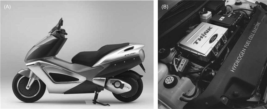
Hydrogen fuel cell technology has currently been fully developed abroad and many products have been introduced, such as electric vehicles and hybrid cars, as shown in Figure 10.3. However, proton-exchange membrane (PEM) materials applied in methanol fuel cells are still far from satisfactory. Early electric vehicles were mainly dependent on lead–acid batteries as the main power source. Because of the long charging time and heavy weight of these batteries, electric vehicles have always been unable to compete with conventional internal combustion engine-driven ones. The most striking difference between the typical internal combustion engines and fuel cells is the lack of endurance. In less than 90 min, the fuel cell vehicles may run out of fuel. To make things worse, it is difficult for them to find premises for refueling. The key to the operation of the PEM is the thin platinum catalyst (expensive); it is plated on both sides of the membrane, accounting for 40% of the cost of the batteries. The biggest problem in the design of fuel cell vehicles is how to make enough fuel available to meet the requirements of customers who drive a certain mileage. In general, a ride of approximately 640 km may take 5–7 kg of hydrogen, but the current prototype vehicles using fuel cells can only carry 2.5–3.5 kg. As a result, the design of fuel cell vehicles still has a long way to go.
10.2.2 Comparison of the Main Fuel Cells
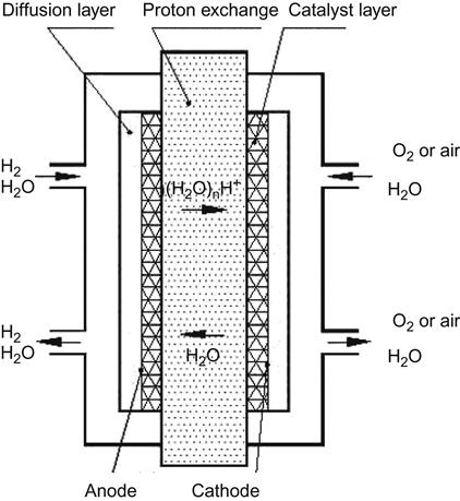
There are many types of fuel cells. Depending on the electrolytes in use, fuel cells can be divided into the following categories: polymer electrolyte fuel cell (PEFC), solid polymer electrolyte fuel cell (SPEFC), proton-exchange membrane fuel cell (PEMFC), alkaline fuel cell (AFC), phosphoric acid fuel cell (PAFC), molten carbonate fuel cell (MCFC), and solid oxide fuel cell (SOFC). A comparison between these categories is indicated in Table 10.4. Currently, the PEMFC is one of the hotspots in fuel cell research, because it is operable at low temperatures and used with solid-state electrolytes. In addition, its application can also be found in industries relying on mobile energy, such as the automobile industry and 3C electronics industry. The core components of PEMFCs include membrane electrode assembly (MEA), gas diffusion layer (hydrogen system), and conductive bipolar plates. Here, MEA is formed by the catalytic electrode and proton conduction membrane, as shown in Figure 10.4. At present, it is urgent to overcome the many flaws in the applications of PEMFCs, such as improving the battery life and lowering the price. PEMFC in the fuel in use can be divided into two categories, hydrogen fuel system and methanol fuel system. In general, the PEMFC is based on hydrogen as fuel, and the system with methanol as fuel is called the direct methanol fuel cell (DMFC). Regarding the global fuel manufacturing giants or famous car makers, such as Ballard, Toyota, Ford, and Honda, PEMCF has matured in device technology development. At present, various fuel cell manufacturing giants are committed to the goal of developing reduced manufacturing costs of PEMCF.
Table 10.4
Comparison of the Major Fuel Cells
| Type | Fuel | Oxidant | Catalyst | Water Management | Power Generation Efficiency | |
| By Temperature | By Electrolyte | |||||
| Low-temperature fuel cell (60–200°C) | Alkaline fuel cell (AFC) | Pure hydrogen | Pure oxygen | Anode: Raney nickel, platinum/carbon Cathode: Raney nickel, platinum/carbon |
Evaporation drainage | 60–70% |
| Proton-exchange membrane fuel cell (PEMFC) | Hydrogen, methanol | Oxygen, air | Anode: Pt/C Cathode: Pt/C |
Evaporation drainage+Power drain | 43–58% | |
| Intermediate-temperature fuel cell (160–220°C) | Phosphoric acid fuel cell (PAFC) | Hydrogen | Anode: Pt/C, Pt–Ru/C Cathode: Pt/C |
Evaporation drainage | 37–42% | |
| High-temperature fuel cell (600–1,000°C) | Molten carbonate fuel cell (MCFC) | Hydrogen, natural gas, coal gas, biogas | Anode: nickel–chromium alloy, nickel–aluminum alloy Cathode: Lithium-oriented–nickel oxide |
Gaseous drainage | >50% | |
| Solid oxide fuel cell (SOFC) | Anode: Ni/YSZ Cathode: Manganese-doped lanthanum strontium |
50–65% | ||||

DMFCs are characterized by large units of energy density, easy assembly, small volume, and ample fuel supplements, so they are suitable for application in 3C electronics, such as portable computers or mobile phones. Thus, European, American, and Japanese manufacturers, such as Smart Fuel, Gore Associates, Toshiba, NEC, and Panasonic, are focusing on funding research and development to develop DMFCs. However, studies found that a DMFC, if working with the same accessories as hydrogen PEMFCs, may have very low power generation efficiency and short battery life. This results from the perfluorinated resin membrane more likely using a PEM in the hydrogen system. For example, Nafion, with a large swelling feature in methanol solutions, has poor barrier properties of methanol, resulting in the serious problem of the proliferation of methanol. Furthermore, it causes the platinum catalyst to be poisoned, which in turn leads to reduced life, or methanol may produce protons without being catalyzed by platinum, directly leading to a reaction with oxygen to reduce the efficiency of fuel use.
10.2.3 Proton-Exchange Membrane
PEM used in fuel cells is required to have the following basic properties: first, high proton conductivity; second, good mechanical strength; third, excellent chemical resistance; and fourth, good durability.
When operating at low temperatures (<80°C), PEMFCs and DMFCs work with the Nafion-based PEM manufactured by DuPont Co. When the operating temperature is higher than 120°C (120–200°C), high-temperature hydrocarbon polymers more commonly used, as reported in the literature, include poly (phenoxy phosphazene) (POP), sulfonated naphthalic polyimide, polybenzimidazole (PBI), alkylsulfonated polybenzimidazole (PBI-AS), sulfonated poly(arylene ether ether ketone) (PEEK-SO3H), sulfonated poly(arylenesulfone) (PSU-SO3H), and so on.
The PEM for the DMFCs is essentially the same as that of the hydrogen PEMFC. The difference is that methanol as a fuel needs special consideration regarding methanol permeability issues. Methanol permeability can cause the overall decline of the fuel cell discharge performance and a shortened life expectancy. Thus, concerning the PEM for direct methanol, we must take into account the methanol permeability problem in the material selection and design.
There are currently many PEM producers. These producers and the materials used for PEM are listed in Table 10.5. As noted, in the hydrogen PEM fuel system, PEM must have good proton conductivity, mechanical strength, and durability. In 1960, DuPont developed Nafion, which was the first PEM broadly in line with these requirements. At present, some other companies also produce fluorine polymer proton-conducting membranes, but they are mostly modeled on the Nafion polymer structure, as shown in Figure 10.5. However, Nafion cannot be directly used in the DMFC system, because the perfluorinated PEM has extremely high penetration of methanol that may reduce the discharge life and performance of fuel cells. The high methanol permeability is rooted in a large channel formed by a large group of ions, and the formation of this large channel is associated with its molecular structure.
Table 10.5
Proton-Exchange Membrane Materials of Foreign Producers
| Company/University/Organization | Membranes |
| US PolyFuel Inc. | Acid-based polyether ether ketone |
| Toshiba | Acid-based polyether ether sulfone |
| Sony | OH-modified fullerene-based membranes |
| JSR Corporation, Japan | Polystyrene sulfonic acid-based compounds |
| Stuttgart University, Germany | Acid-based ionomer blends |
| Los Alamos National Laboratory (LANL) | Sulfonation sulfone polymer; PVDF-g-SPS |
| Ballard | Sulfonated-F-styrene |
| DuPont | Modified Nafion |
| Japan’s Asahi Glass Co., Ltd. (Asahi Glass) | PFS/PTFE fibrils |
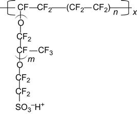
As indicated in Figure 10.5, perfluorinated PEM materials are usually designed by using carbon–fluorine resin as a polymer main chain to increase the membrane’s chemical stability, thermal stability, and mechanical strength. In addition, the side chain-induced sulfonic fluorocarbon short chain has a proton conduction function. Nafion has high proton conductivity because the short-chain fluorocarbon sulfonic acid group has good mobility and can form acid-based clusters, which, in the case of water absorption, will soften the main chain of fluorocarbon polymer and increase the proton conduction pathway. However, because of the increased proton pathway, in the methanol fuel cell system the methanol molecules travel through the large channel at an increased rate. A perfluorinated resin with high methanol permeability would cause a shortening of life expectancy as a whole, dramatically reducing the power generation efficiency and effectiveness. To increase the efficiency of methanol fuel cells in power generation and battery life, the current research and development trend in methanol fuel cells is to reduce the methanol poisoning of the platinum catalyst or the methanol permeability of the PEM. To reduce the methanol permeability of the PEM, the PEM must be improved. This can be achieved in two ways. One way is the original perfluorinated proton-exchange membrane. For example, Nafion is modified by way of adding solid acid or inorganic oxides to reduce the number of channels in the perfluorinated membranes for methanol permeability, or by the use of different polymers doped with other polymers to limit the swelling of Nafion. Alternatively, the inorganic porous material can be impregnated with Nafion to reduce the swelling of Nafion, or the Nafion PEM is added with a good methanol barrier membrane on both sides. Another method is to use nonfluoride, high-performance engineering plastics containing a benzene ring, such as polyamide, PES, PEEK, or polymers containing more benzene. These materials are inexpensive and characterized by good chemical stability, mechanical strength, and thermal stability. Many researchers are trying to use the nonfluorine polymer sulfonic acid treatment to obtain a sulfonation polymer that can be used in PEM. The generated sulfonic acid enables the sulfonic acid polymer to have proton conductivity, which is related to sulfonation. For the same polymer, the level of sulfonation is proportional to the level of proton conductivity. However, as sulfonation is increased, water absorption of materials will be increased as well. When sulfonation is greater than a specific value, the membrane immersed in water will absorb a large amount of water, causing the swelling of polymer or even dissolution. In the preparation of a PEM using sulfonic acid polymer, the requirement for proton conductivity to achieve the level of Nafion will lead to an increase of sulfonation. However, while enhancing the proton conductivity, membrane dissolution will occur subject to the increased moisture in the membrane. This makes the sulfonic membrane distinct from Nafion in terms of proton conductivity. Therefore, in the case of low moisture content, the postsulfonic acid polymer cannot have high proton conductivity. To improve this, research has shifted toward the direct synthesis of nonfluorinated sulfonic acid polymer systems. The results showed that, by way of direct synthesis of sulfonic acid-based polyimide, the resulting PEM can have conductivity slightly lower than Nafion. Nonetheless, the methanol permeability was less than one-tenth that of Nafion. In addition, sulfonic acid-based polyamide is also lower than Nafion in moisture content. It is critical for the proton conductive membrane to be able to maintain high proton conductivity at low moisture content. This is because when the DMFC anode has contact with air, proton conductive membranes with low moisture content may have a water evaporation rate lower than that of proton conductive membranes with high moisture content. Therefore, the water dissipation can be reduced to increase the usage time of methanol fuel.
10.2.4 Nanofuel Cells
The nanofuel cell is one of the fuel cells based on the use of nanomaterials and nanotechnology. The small fuel cells (< 500 W) are currently undergoing research and development. It involves using 2-nm to 3-nm electrochemical catalysis and technology of organic–inorganic hybrid nanomaterials (e.g., PEM), leading to the development of integrated fuel cell technology. Low cost and high efficiency have become the most critical bottlenecks for its practical use.
Conventional fuel cells generally use hydrogen fuel. Compared with hydrogen, methanol as a liquid has high density and can be more safely stored, so the methanol fuel system has considerable potential for development. In addition, propane gas is currently applied in some of the nanofuel cells being developed. This material can be easily purchased. The US-based NanoDynamics, Inc. is now developing a 50-W SOFC. The prototype is only the size of a loaf of bread, with 20% of its components being manufactured with nanomaterials. As such, a battery can store 3,000 W·h of electricity using just 5 pounds of propane. Under the same conditions, the traditional SOFC can only store one-third to one-half the electricity of the present fuel cell. This 50-W SOFC with nanomaterials is a prototype of fuel cells that was originally designed for battlefield soldiers. Such a battery can supersede the traditional batteries weighing 35 pounds.
In addition to using nanomaterials, NanoDynamics also renovated the various parts of these battlefield batteries dedicated to the soldiers, including the membrane, electrode, and battery catalyst, to enable them to become more portable. At the same time, the storage capacity of the fuel cell is improved. This should be higher in the requirements for battery storage capacity.
Fuel cell energy comes from the chemical energy released from the generation of water in the reaction of hydrogen and oxygen. Platinum in the fuel cells is the catalyst in the catalytic reaction. However, subject to the side effects occurring in the vicinity of the cathode, platinum would gradually lose catalytic oxidation ability. This is one of the challenges in the practical application of fuel cells. Studies have shown that platinum electrodes for fuel cells, if plated on gold nanoparticles with a diameter of approximately 2–3 nm, will increase the platinum oxidation potential, making the metal less susceptible to oxidation. The platinum electrode can be protected from damage in this way. The studies also showed that the catalytic ability of platinum will not decline when the surface is blocked by gold nanoparticles, that is, platinum plated with nanogold still has catalytic reaction capabilities.
10.3 Dye-Sensitized Nanocrystalline Solar Cells
10.3.1 Status of Solar Cells
In 1954, Bell Labs in the United States produced the world’s first practical solar cell with efficiency of 4%, which was applied to the US satellite Vanguard-1 in 1958. Later, solar cells gradually entered into the ground application of electricity from space. A home photovoltaic system of 4 kW on the roof is able to meet the average family’s electricity needs, with the annual reduced CO2 emissions equivalent to the annual emissions of a family car. Along with the continuous improvement in the material, structure, process, and other aspects, the present price of solar cells is less than 1% of that in the 1970s. It is expected that in 10 years, solar energy will be able to compete with thermal power in terms of cost of power generation in the United States, Japan, and Europe. At present, solar energy has an average annual growth rate of 35%, presenting the fastest growth in the energy technology industry.
10.3.2 Types of Solar Cell
Solar cells can be divided into the inorganic type or the organic type, according to the materials used. Inorganic materials commonly used in solar cells are semiconductor silicon (monocrystalline, polycrystalline, amorphous, complex, etc.) and compound semiconductors (GaAs, CuInSe2, CdTe, InP, etc.). Silicon solar cells (monocrystalline silicon, polycrystalline silicon, amorphous silicon) have relatively higher photoelectric conversion efficiency, but the cost is also high and the preparation process is complex. In addition, the batteries made from multi-compound materials, such as inorganic salts, including gallium arsenide, cadmium sulfide, and copper indium selenium, contain cadmium and other toxic elements, as well as indium, selenium, and other rare elements, and therefore they are inferior in security and price.
Materials commonly used in organic solar cells are organic semiconductors (zinc phthalocyanine, polyaniline, poly p-phenylene vinylene, etc.). There are also other photochemical solar cells using nano-TiO2. Solar cells made from functional polymer materials are presently still in the early stage of research and development and are characterized by low conversion efficiency and short service life.
10.3.2.1 Inorganic Solar Cells
Semiconductors can make use of different barriers, such as p–n junction, Schottky barrier, and heterojunction, to have a photovoltaic effect. When the solar cells are exposed to sunlight, the interaction of light and semiconductors can produce photo-carrier and the resulting electron–hole pairs separated from the poles depend on the formation of the semiconductor barrier, while the positive and negative electric charges are collected by the upper and lower electrodes respectively. Formed by the charge accumulation, the electric current will flow to the load through the metal wire. Inorganic solar cells, especially thin-film batteries, are currently predominant on the market. The following is a brief introduction to the principal types on the market.
10.3.2.1.1 Silicon Wafer Solar Cells
Wafer mostly refers to monocrystalline silicon wafer, derived from the ordinary system of silicon salad. It is the most commonly used semiconductor material and can be divided into 4-, 5-, 6-, and 8-in. sizes by diameter. Recently, a 12 in. or greater specification has been developed. The larger the wafer, the more devices can be integrated on the same piece. At the same time, enlarging the size can reduce the cost but requires higher technology for materials and production. In 1954, Bell Labs claimed the successful development of the first silicon wafer solar cell, which showed luminous efficiency of 6%. With the subsequent development of integrated circuits, this type of solar cell has been predominant on the market; its market share has never fallen below 80%. If we only consider the market power of more than 1 kW, then this figure can almost reach 100%. This can be broadly attributed to three factors: first, cost and price; second, the module efficiency; and third, the scale and capacity utilization.
As the technology advances, remarkable improvements have been made in terms of the wafer thickness, cutting technology, wafer size, as well as wafer price. Since the 1960s, such cell power generation has led to a decline of approximately 50 times the unit per watts cost. The current price is approximately US$2.5 to $3/watt. Over the past 10 years, thin-film solar cells have seen a substantial decline in manufacturing costs, showing a trend even faster than that of the silicon wafer; however, so far, their price has generally remained at approximately 50% higher than the silicon wafer.
The optical efficiency in laboratories for the silicon wafer single-cell system now stands at 25%, which is very close to the theoretical value of 29%. Since the 1970s, the commercial products have also advanced greatly in optical efficiency, amounting to approximately 12% in recent years. This technical achievement, relatively speaking, is beyond the reach of the majority of thin-film technologies.
Production costs are often deeply affected by production scale, and solar cells are no exception. In comparison to the thin-film type and silicon wafer type, in general the former is approximately 10 times that of the current production capacity of the latter. Therefore, fixed costs can be substantially divided. Followed by capacity utilization, the current manufacturers of the silicon wafer type, due to the continuous significant market growth in recent years, present an average capacity utilization of approximately 80%, while the thin-film manufacturers only present an average capacity utilization of approximately 40%. This makes the silicon wafer type more competitive when it comes to production costs, thus contributing to its larger market share.
10.3.2.1.2 Amorphous Silicon Solar Cells
Amorphous silicon solar cells are the most well-developed thin-film solar cell. The structure usually has the p-i-n (or n-i-p) type of duality, where p-layer and n-layer are mainly used for establishing an internal electric field (i-layer) comprising amorphous silicon. Because amorphous silicon has a high absorption capacity, the i-layer usually has a thickness of 0.2–0.5 μm. Its absorption frequency ranges between 1.1 and 1.7 eV, which is different from that of the silicon wafer, which has an absorption frequency of 1.1 eV. Unlike the crystal, the structural homogeneity of amorphous material is relatively low. Electrons and holes are conducted inside the material; therefore, in the case of long distance conduction, there may be a high composite probability of the two. To avoid this phenomenon, the i-layer should not be too thick or too thin, because the latter problem can easily lead to inadequate absorption. To overcome this predicament, a multilayer structured stack is often used in the design of amorphous silicon solar cells to achieve a balance between the optical absorption and photoelectric efficiency.
The inherent inadequacy of such photovoltaic cells is a short-term but significant decline in the performance after light exposure, also known as the SWE effect, with the rate of decline between 155% and 35%. It is caused by some of the unsaturated silicon atoms in the material, which may show structural changes due to light exposure. The aforementioned multilayer stack approach is a candidate for overcoming the SWE effect.
The manufacture of amorphous silicon photovoltaic cells is based on plasma-enhanced chemical vapor deposition (PECVD), which can be used to produce silicon thin film. Substrate can be made of the flexible and inexpensive material in larger sizes, for example stainless steel or plastic materials. The process is the roll-to-roll method. The evaporation process is slow, and the high-quality conductive glass layer is very costly, so its total manufacturing cost is only slightly less than that of crystal solar cells. As for the multilayered stack model, improved battery efficiency also comes with an increased cost. In summary, although it does not have advantages in terms of cost, this type of solar battery output has shown rapid growth in the past 3 years; in 2003, there was an annual growth of 113%. It is expected that this trend will continue.
To reduce manufacturing costs, it has been developed using VHF plasma in the manufacture of membrane, enabling the process speed to be increased fivefold. Meanwhile, SnO2 may supersede ZnO as the conductive glass material to reduce the TCO costs. Once this process is successfully developed, it would greatly enhance the competitiveness of amorphous silicon solar cells. The greatest weakness is its low photoelectric conversion efficiency. At present, the efficiency is approximately 13.5% in laboratories only and 4–8% in commercial modules. It seems the scope for future improvement may be quite limited.
10.3.2.1.3 Copper Indium Gallium Diselenide Solar Cells
There are two kinds of copper indium gallium diselenide solar cells. One is referred to as CIS, containing copper, indium, and selenide, and the other is CIGS, containing copper, indium, gallium, and selenide. It is popular because of its higher efficiency and low cost of photoelectric materials. The optical efficiency of CIGS solar cells made in laboratories can be up to approximately 19%; when it comes to the module, the maximum value can still reach approximately 13%. Depending on the differences in the percentage of indium and gallium, CIGS may have a light absorption range that varies from 1.02 to 1.68 eV. This feature can be used for multistack modules to further enhance the organizational effectiveness of the battery. In addition, due to the high absorption efficiency (α>105 cm−1), the required thickness of photoelectric materials will not be larger than 1 μm, and 99% or more of the photons can be absorbed. It is generally estimated that the semiconductor materials required for the mass production of this kind of cell may be US$0.03/W only.
CIGS photovoltaic cells are different from amorphous silicon solar cells in structure, mainly due to a buffer layer that exists between the optical layer and the conductive glass. The layer material is usually chromium sulfide (CdS). The carrier can also be made of a flexible material, so the roll-to-roll mode is available for the process. At present, the commercial process is being developed by Shell Solar and includes a series of vacuum procedures, which has led to very high investment in hardware and manufacturing costs. An estimate showed that investment in this production process is approximately US$33 for 1 m2. Simultaneous evaporation is commonly used in laboratory production techniques, but its amplification is not easy and may not be viable commercially. Another company, ISET, has been actively involved in the development of nonvacuum techniques trying to use nanotechnology similar to the ink process in preparation of the layered results. The company reported that initial success has been achieved, but whether it can develop itself into a commercial manufacturing process is unknown. In addition, NREL in the United States has successfully developed a three-stage process that was a great success in the laboratory in obtaining solar cells with an optical efficiency of 19.2%. However, the complexity of the production process and the high costs are detrimental to any further progress being made.
In summary, despite advantages such as high photovoltaic efficiency and low material cost, CIGS also has many difficulties. For example, three problems must be solved. The first is complex process and high investment costs. Although many organizations are working to improve the process, it is rather difficult to reduce costs in this way. Second is supply of key raw materials. CIGS material involves the use of the indium element, which is a potential problem because the natural reserves of indium are very limited. Researchers abroad have made some calculations based on a 10% battery efficiency, indicating a wide application of CIGS photovoltaic electricity as a major energy resource will use all the natural indium within only a few years. Third is the potential toxicity of the CdS buffer layer. The toxicity of cadmium (Cd) has been a concern. The fact that improper leakage of CdS in the cell will cause environmental harm makes people uneasy. Therefore, most countries in Europe have stopped studying this type of photovoltaic cell.
10.3.2.1.4 Cadmium Telluride Thin-Film Solar Cells
Cadmium telluride thin-film solar cells (CdTe) have the longest history of the thin-film photoelectric cells, so they have been the focus of more research. In 1982, Kodak took the first step forward in the manufacture of cadmium telluride thin-film solar cells with optical efficiency of more than 10%. At present, the highest electro-optical efficiency achieved in the laboratory is 16.5%, which was completed by the NREL laboratory in the United States. The goal is to make further incremental changes in the established battery configuration, and such changes are used in some of the materials.
The typical structure of CdTe photovoltaic cells displays the formation of the main body of an approximately 2-μm p-type CdTe layer and the n-type CdS with thickness of only 0.1 μm. Photon absorption occurs mainly in the CdTe layer, with efficiency of the absorption coefficient greater than 105 cm−1. Therefore, a thickness of only a few microns is available to absorb more than 90% of the photons. The upper edge of the CdS layer first links to TCO and then connects to the substrate, while the upper edge of CdTe is linked to the back panel to form a photovoltaic cell structure. It is known that in making CdTe solar cells, regardless of the battery structure, a cadmium chloride-activated semiconductor layer is required. The preparation methods include wet or dry steam. The dry steam method is used by the industrial sector more often.
As for the preparation of the membrane used for CdTe photovoltaic cells, there are a number of available processes, among which are a few methods that are suitable for mass production. The known methods are sputtering, CVD, atomic layer epitaxy, screen printing, galvanic deposition, chemical spraying, close-packed sublimation, modified close-packed sublimation, and sublimation–condensation. Each method has its advantages and disadvantages. Current deposition is the least expensive one, and thus becomes the main approach used in industry. It consumes the least tellurium.
Although the CdTe solar cells possess many of these procompetitive factors, its market share is still low. The reason why CdTe solar cells cannot be promoted to the mainstream market may be summarized as follows. Both the module and the substrate material are too costly. The overall CdTe solar cell material accounts for 53% of the total cost; here, semiconductor materials only account for approximately 5.5%. The natural reserves of tellurium are limited. If humans rely on it for substantial and comprehensive photovoltaic power generation, then its total amount cannot meet the demand. Cadmium is toxic. People cannot use such photovoltaic cells without worrying about the toxicity.
10.3.2.1.5 Silicon Thin-Film Solar Cells
The development of silicon thin-film solar cells started in the 1970s, but there was no big breakthrough until the 1980s. The thickness of the silicon crystal layer should be only 5–50 mm, so the acceptable substrates can be sub-silicon materials, glass, ceramic, or graphite. In addition to the substantially reduced amount of silicon material used, this type of photovoltaic cell is not as strictly required as silicon wafer solar cells in the purity of silicon material due to the short distance of conduction between electrons and holes, so material costs can further decline. Silicon material does not have as high an absorption efficiency as other semiconductor photovoltaic cell materials in development; in optical cells of this type, the film thickness of the silicon layer is not as thin as silicon-based solar cells, which can reach approximately 300 microns of silicon layer thickness. Thus, in design, the concept of optical hysteresis should be introduced to improve the light absorption rate. This point is different from other thin-film photovoltaic cells.
The preparation methods for this type of photovoltaic cells include liquid phase epitaxy, many types of CVD, including low pressure and atmospheric pressure chemical vapor deposition (LPCVD, APCVD), PECVD, ion-assisted chemical vapor deposition, as well as hot-wire chemical vapor deposition. Unfortunately, none of these methods can be used in industry. Nonetheless, it is generally believed that APCVD can be adopted in mass production. For the aforementioned vapor deposition method, its operating temperature ranges from 300 to 1,200°, depending on the differences in substrate materials.
This type of photovoltaic cell has reached 21% of optical efficiency at the maximum laboratory level. In the market, the product is only available in Astropower. With a graphite substrate, the efficiency is approximately 13.4%. Because the graphite material is expensive, the current studies concentrate on the use of glass or high-temperature substrate, or the transfer of the semi-finished products of the monocrystalline silicon layer to the glass substrate to supersede the graphite. Japan’s Mitsubishi Corporation has successfully used this method in the preparation of components of 100 cm2, with optical efficiency of up to 16%. Overall, this type of photovoltaic system is still in the verification period of feasibility. Whether the laboratory preparation technology can be developed into a mass production process to bring about economic benefits is another focus of attention.
10.3.2.2 Organic Solar Cells
Organic solar cells are made with organic semiconductors, which follow the working principle that organic semiconductors may produce electrons and holes that are bound in excitons while separation of the electron and hole occurs in the interface (the junction of electrodes and conductive polymers).
In recent years, the major advance in organic solar cells has been the first generation of plastic solar cells developed with plastic nanotechnology by scientists at the University of California (Berkeley) in 2002. These cells can be installed in various portable devices and wearable electronic devices to provide 0.7 V voltage.
Organic solar cells are characterized by low price, easy shaping, and performance control by chemical modification.
In organic solar cells, the most important type is the dye-sensitized nanocrystalline solar cell, which is actually an organic and inorganic complex.
10.3.3 Dye-Sensitized Nanocrystalline Solar Cells [6–8]
DSSCs are developed mainly on the basis of mimicking photosynthesis. It is a new type of solar cell, with its main advantages being abundance of raw materials, low cost, relatively simple technology, and more advantages in large-scale industrial production. Furthermore, all raw materials and production processes are nontoxic and nonpolluting, and some of the materials can be fully recovered. This is of great significance to the protection of the human environment. Dye-sensitized nanocrystalline solar cells may have a cost that is merely one-fifth to one-tenth that of silicon solar cells and a service life of up to 15–20 years. Thus, DSSCs represent a promising clean solar energy conversion device. Research on DSSCs will help alleviate the energy crisis in the world today with significant practical potential.
10.3.3.1 The History of Dye-Sensitized Nanocrystalline Solar Cells
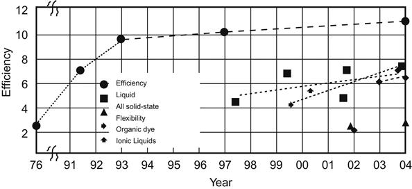
In 1991, O’Regan and Gratzel [9] at Ecole Polytechnique Fédérale de Lausanne, Switzerland, reported a new type of highly efficient solar cell with dye-sensitized nanocrystalline TiO2 films as light anode, symbolizing the emergence of the world’s first nanosolar cell. DSSCs can achieve photoelectric conversion efficiency more than 7% at a lower cost, providing a new way to use solar power.
In 1997, the DSSC’s photoelectric conversion efficiency reached 10–11%, short-circuit current reached up to 18 mA/cm2, and open circuit voltage reached 720 mV.
In 1998, the use of solid organic hole transport materials to supersede the solid-state DSSCs with liquid electrolytes was successful. Its monochromatic photoelectric conversion efficiency of up to 33% attracted worldwide attention.
At present, the photoelectric conversion efficiency of DSSCs can be maintained at 10%, life expectancy is 15–20 years, and its manufacturing cost is only one-fifth to one-tenth that of silicon solar cells [10].
DSSCs comprise an organic–inorganic composite system. The advantage of DSSCs is that they can be made into products of transparency, so they have a wide range of applications. They can be used in a variety of lighting conditions and have high light utilization efficiency. In addition, they are not sensitive to light and shadows and can work in a wide temperature range (Figure 10.6).
10.3.3.2 Cell Structure
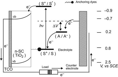
Dye-sensitized nanocrystalline solar cells (DSSCs; also known as Grätzel-type photoelectrochemical solar cells) mainly include glass substrates coated with a transparent conductive film, the dye-sensitized semiconductor materials, such as electrode pair and electrolyte several parts (Figure 10.7). In Figure 10.7, the anode in the electrode pair is dye-sensitized semiconductor film, such as TiO2 film (5–20 μm, 1–4 mg/cm2); the cathode is platinum-plated conductive glass and the electrolyte is ![]() .
.

Titanium dioxide thin-films electrolyte Pt mirror
10.3.3.3 Working Principle
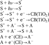
The working principle of DSSCs is shown in Figure 10.8. Semiconductor TiO2 has a band gap of 3.1 eV, so absorption occurs in the ultraviolet region. After surface adsorption to the dye sensitization, the good response of dye to visible light can help to expand its absorption into the visible light region. DSSCs are actually a heterojunction photoelectric conversion device. The sunlight on the cell will be absorbed by electrons in dye molecules, which can then jump to the excited state. Excited state electrons will be quickly injected into the TiO2 conduction band via TiO2 film, quickly reaching the contact surface between the membrane and conductive glass. It will be collected in the conductive substrate and flow toward the electrode through the external circuit.
The principle in Figure 10.8 can be expressed by the following reaction equation, with the same symbols as shown in the figure:
10.3.3.4 Parameters for Performance Evaluation
The performance indicators of DSSCs are mainly the incident photon-to-current conversion efficiency (IPCE) and the total conversion efficiency (ratio of output power and input power) ![]() .
.
The incident monochromatic light photoelectric conversion efficiency (IPCE) is defined as
(10.1)
Here, ![]() is photocurrent density in
is photocurrent density in ![]() ,
, ![]() is the optical wavelength in nm, and
is the optical wavelength in nm, and ![]() is the flux by
is the flux by ![]() .
.
Alternatively, IPCE can be expressed as:
(10.2)
Here, ![]() is the light absorption efficiency,
is the light absorption efficiency, ![]() ; Γ is the number of moles of dye covering the surface of membrane per unit of square centimeter, δ(λ) is cross-sectional area of dye absorption,
; Γ is the number of moles of dye covering the surface of membrane per unit of square centimeter, δ(λ) is cross-sectional area of dye absorption, ![]() is the efficiency of electron injection,
is the efficiency of electron injection, ![]() , kinj indicates rate constant of electron injection, τ is the lifetime of the excited state, and
, kinj indicates rate constant of electron injection, τ is the lifetime of the excited state, and ![]() is the efficiency of the electrode in charge collection.
is the efficiency of the electrode in charge collection.
There are three main factors that may affect the photoelectric conversion efficiency of the cells: (1) lighting efficiency, mainly dependent on the optical absorption of an organic photosensitive dye; (2) electronic injection, mainly dependent on the energy level matching between the organic photosensitive materials and nanocrystalline semiconductor materials; and (3) collection efficiency, mainly determined by the proliferation of electronic properties in the film.
The total conversion efficiency (ratio of output power and input power) is calculated as follows:
(10.3)
Here, iph is short-circuit photocurrent or, in other words, the current at short circuit (i.e., resistance is zero, only to connect the electrode pair and ammeter), which is the largest photocurrent that can be generated by photovoltaic cells. Voc is open circuit photovoltage, which is the voltage at open circuit (infinite resistance, only to connect the reference electrode and voltmeter). It is the maximum voltage that can be generated by photovoltaic cells. Theoretically, the open circuit voltage Voc is equal to the Fermi energy level of the semiconductor TiO2 in light minus the Nernst reversible redox potential of electron pairs in electrolyte; ff is fill factor. It is defined as the ratio between the product of current (Iopt) and voltage (Vopt) against the product of the battery short-circuit current and open circuit voltage when the battery has a maximum output power (Popt):
(10.4)
Is is the incident light intensity.
10.3.3.5 Research Progress
There has been progress in the research on dye-sensitized nanocrystalline solar cells in the aspects of sensitizer, nanosemiconductor materials, and electrolytes.
10.3.3.5.1 Sensitizer
Dye-sensitized nanocrystalline solar cells require the sensitizer to be:
1. able to absorb sunlight as much as possible;
2. closely adsorbed on the surface of the nanocrystalline network electrode;
3. able to match the corresponding nanocrystalline energy band;
Dye-sensitized nanocrystalline solar cell sensitizers are mainly divided into the following four series: bipyridyl metal complex series, phthalocyanine series, porphyrin series, and pure organic dye series.
At present, bipyridyl metal complex is still the best and the most widely used dye sensitizer. Bipyridyl metal complex series have typical representatives N3 and black dye. Figure 10.9 indicates the formulae of N3 and black dye.
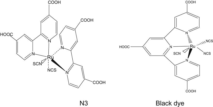
Figure 10.10 is a comparison of N3 and black dye regarding the incident monochromatic IPCE.
The pure organic dye family may be either semi-cyanine dye or coumarin derivatives. Their performance is not discussed here.
10.3.3.5.2 Nanosemiconductor materials
Oxides of metal sulfides, metal selenium compounds, perovskite, and titanium, tin, zinc, tungsten, zirconium, hafnium, strontium, iron, and cerium can all be used as semiconductor materials in DSSCs. For example, the optical and chemical properties of Nb2O5 DSSCs were reported in 1999 [11], and those of the nanocrystalline In2O3 thin-film electrode were reported in 2000 [12].
The use of nanoscale semiconductor materials such as TiO2, ZnO, and SnO2 as photovoltaic solar cells is extremely popular in research worldwide; the nontoxic nano-TiO2 of light stability is the most commonly used material for study of photovoltaic solar energy conversion cells.
As mentioned, the two major crises humankind is facing in the twenty-first century are energy and pollution. TiO2 will play a significant role in resolving these two issues. In Chapter 9, for example, we introduced the photocatalytic application of TiO2. Here, we mainly focus on the application of solar cells.
As indicated in Table 10.6, TiO2 is a high-refractive index semiconductor with a high dielectric constant that is conducive to the absorption of UV light; therefore, it can be used as micro-electromechanical material, photocatalyst, and in micro-light decomposition, as well as anti-fog and self-cleaning coatings and for light-grating. TiO2 nanoporous membrane has the advantages of having high porosity and a large surface area. When applied in DSSCs, it can absorb more dye molecules. In addition, the mutual reflections between the grains within the films are able to enhance the absorption of sunlight. Thus, in addition to ensuring high photoelectric conversion quantum efficiency, dye-sensitized nanocrystalline TiO2 semiconductor electrodes can further guarantee the high efficiency of light capture. The nanometer TiO2 electrode is the key to the performance of solar cells, which is directly related to the efficiency of solar cells.
Table 10.6
| Physical Properties | Rutile | Anatase |
| Molecular weight (g/mol) | 79.866 | 79.866 |
| Density (cm3/g) | 4.25 | 3.89 |
| Lattice constant a (nm) | 0.4594 | 0.3785 |
| Lattice constant c (nm) | 0.2962 | 0.9514 |
| Crystal structure | Square | Square |
| Number of formula units in the cell | 2 | 4 |
| Band gap (eV) (corresponding to UV light wavelength, nm) |
3.0 ~410 |
3.2 ~385 |
| Hardness (Mohs) | 6–7 | 5.5–6 |
| Refractive index | ||
| Air | 2.7 | 2.55 |
| Water | 2.1 | 1.9 |
| Oil | 1.85 | 1.7 |
| Dielectric constant (powder state) | 114 | 48 |
| Specific heat (kJ/°C kg) | 0.7 | 0.7 |
| Melting point(°C) | 1,855 | Transformed into rutile |
Methods of preparation of nano-TiO2 thin-film electrode materials mainly include the sol–gel method, hydrothermal reaction, sputtering, alkoxide solution, sputtering deposition, plasma spraying, and screen-printing methods.
10.3.3.5.3 Electrolyte
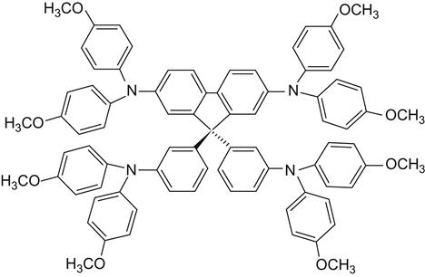
Liquid electrolyte is found to have some obvious shortcomings. It tends to lead to dye-sensitized desorption. It is a volatile solvent in reaction with sensitizing dyes and leads to dye degradation. It has a complex sealing process, with long-term placement caused by electrolyte leakage. Sealant reaction with the electrolyte still exists in cell, electrode, with light corrosion, and can easily become dye-sensitized in desorption. It has a very slow carrier mobility rate and instability in high-intensity illumination. It also has the presence of other oxidation–reduction reactions. At present, researchers have prepared all solid-state nanosolar cells using solid-state organic hole transport materials to replace the liquid electrolyte, allowing for gratifying progress. For example, in 1996, Masamitsu and colleagues prepared complete solid-state solar cells using solid polymer electrolyte and obtained high ionic conductivity of the electrolyte using a special preparation method. A continuous photocurrent was achieved with 0.49% of the photoelectric conversion efficiency. In 1998, Grätzel and associates used 2,2′, 7,7′-4 (N, N-2 pairs of p-methoxyphenyl-amino)-9,9′-spiro-2-fluorene (OMeTAD, shown in Figure 10.11) as a hole transport material. The result was a cell with 0.74% of the photoelectric conversion efficiency and color efficiency as high as 33%. This has sparked worldwide attention and enabled nanosolar cells to make a huge step forward in the solid state [13].
10.3.3.6 Main Problems
1. Dyes
Dye photosensitizer is key to the battery. It requires not only a wide range of absorption of sunlight, combined with good adsorption properties of semiconductors, but also suitable oxidation–reduction potential (excited dye to match with the semiconductor conduction band potential enables electrons to be effectively injected into the semiconductors), long lifetime of excited states, good photoluminescence and stability that can withstand at least 108 excited oxidation–reduction occurrences, ease of synthesis, and low cost. Now, N3 is a widely recognized dye that shows better performance, but its preparation process is more complicated and therefore more expensive. At present, the search for low-cost dyes exhibiting good performance has become a popular topic of research. Development of new dyes to supersede organic ruthenium metal (referred to as N3), the currently accepted best dye, is also very popular. Organic dye chemistry is a field undergoing considerable academic and industrial development. Many people believe that after a certain stage of theoretical preparation and a series of experiments, there should be opportunities to develop organic dyes with an absorption capacity better than N3. If this becomes true, then it may reduce the cost of dyes and be free from the requirement of using the precious metal ruthenium.
2. Nanomaterials
The wider the band gap of semiconductor, the higher its light stability. From this perspective, if a material with a gap wider than that of titanium dioxide is used, then better DSSC product durability can be expected. At present, many scientists are engaged in research in this area, but no satisfactory results have been reported.
3. Electrolyte and Substrate Materials
Liquid electrolyte can easily experience leakage during working conditions, which is a serious problem for the battery package, and there is also major difficulty in commercializing DSSCs. To achieve commercial objectives, the solution electrolyte should be gradually replaced by solid electrolyte, aiming to improve stability and provide longer service life.
4. Series and Parallel Connection of Cells
One of the international focuses of research is nano-TiO2 single-liquid junction solar cells that are arranged in series to improve the open circuit voltage.
10.3.3.7 Flexible DSSC Cells
In recent years, a flexible DSSC has attracted the attention of researchers. It has polymer materials (e.g., flexible ITO) that are used to replace the traditional glass substrate, so that the weight of the battery can be reduced and the battery can even be bent, thus expanding the scope of application of the cells. Satoshi Uchida at Tohoku University, Japan [14], used TiO2 powder hot-synthesized with TiO2 precursor sol and water as a coating for ITO/PET and sintered it for 5 min with 28 GHz microwave to prepare a TiO2 porous electrode. Its battery photoelectric conversion efficiency increased to 2.16%. Resistivity of ITO conductive film shows rapid growth in high-temperature conditions, and PET polymer substrate is subject to heat-resistant temperatures below 150°. Therefore, the critical step is to achieve low-temperature preparation of TiO2 thin films on flexible ITO/PET conductive substrate.