Appendix 1
Geometrical Optics, Photometry and Energy Elements
A1.1. Geometrical optics elements
A1.1.1. Refractive index
The refractive index characterizes the ratio of the speed in vacuum (cv) to the speed in another homogeneous environment (ce). In the latter environment, the optical wave propagates at a speed lower than that in vacuum cv. The ratio is expressed by the following equation:
Table A1.1 presents some refractive index examples.
Table A1.1. Examples of refractive indexes
| Environment | Refractive index |
| Vacuum | 1 |
| Air | 1.00029 |
| Water | 1.3333 |
| Glass | 1.5 |
| Diamond | 2.41 |
When the optical wave passes from one environment to another, not only its velocity (speed) but also its trajectory changes. In addition, this index varies with wavelength, which can cause optical aberrations (e.g. the phenomenon of light scattering in a prism).
A1.1.2. Fermat’s principle
Fermat’s principle is the basis for any geometrical optics that describes the refraction and reflection laws. Under this principle, the path followed by a light beam between two points A and B is such that the travel time between these two points is minimum. Then the light propagation is straight in a homogeneous medium with constant velocity (in classical Euclidean geometry). This feature also applies in the context of a path from B to A (principle of light reversibility).
As such, a set of optical waves form an optical beam whose trajectories fall into three categories:
– Parallel beam: the rays are parallel.
– Divergent beam: the rays originate from a single point.
– Convergent beam: the rays propagate toward the same point.
A1.1.3. Snell–Descartes’ laws
When a ray passes from a homogeneous environment to another homogeneous environment with a different refractive index, part of this ray is reflected, and the other part is transmitted toward the second environment.
Snell–Descartes’ laws describe the trajectory of these rays (case of the crossing from an n1 index environment to an n2 index environment with n1 < n2).
– Descartes’ first law: the incident, reflected, and transmitted rays are contained in the same plane.
– Descartes’ second law: the angles for the incident ray (i) and the reflected ray (r) are equal.
– Descartes’ third law: regarding the refracted/transmitted ray: the rule is as follows: n1.sin i1 = n2.sin t. If the n1 index environment is air (n1 = 1), then the refractive index n2 of the second medium is the ratio of sinus of the angles i and t.
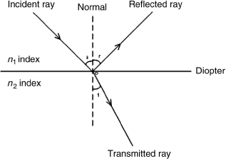
Note that an absorption phenomenon may occur in case the environment is not completely transparent.
For a mirror, there is no transmission, the ray is completely reflected. In the case of a glass diopter (lens, prism, etc.), depending on the surface treatment, about 4% of the wave is reflected and the rest is transmitted.
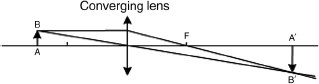
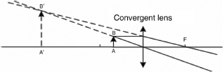
A1.1.4. Definitions: sources, image, andfocal point
Source: the object from which the optical rays originate.
Spot object or spot source: a dimensionless source — or equivalent (a star, for example). Even if it bears a nonzero size, its distance allows it to be considered as a spot source.
Extended object or source: a nonzero size source. The rays are emitted from different points of the source (the Sun, for example).
Real object: a real object is a spot or an extended source from where divergent rays radiate.
Real image: a real image is the area of space where the light rays from one source converge after passing through an optical system. A real image can be projected on a screen.
Virtual object: an object or a virtual image is the area of space corresponding to the imaginary extension of optical rays. The virtual object is downstream from an optical device, while the virtual image is upstream. A virtual image cannot be projected on a screen.
Focal point: any light beam (from infinity) parallel to a converging lens’ optical axis converges to a point called the focal point (F). Conversely, any image at the focal point for a diverging lens seems to come from infinity (inverse return of light). The focal point position is determined by the geometry of the lens and its refractive index.
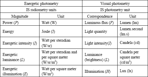
A1.2. Photometry elements
Optical radiometry or photometry consists of measurement of the energy flux associated with optical electromagnetic radiations. The basic elements are flux, intensity, illumination, and luminance. An optical radiation source emits a luminous flux in potentially all directions of space. This flux has an intensity value for any given direction. A surface, located at a defined distance from the source, receives a given irradiance value.
Before going further, it may be wise to recall the definition of some physical quantities in the fields of visual and energetic photometry.
A1.2.1. Steradian
A steradian (sr) is a unit of solid angle which, its apex located at the center of a sphere, has on the surface of the sphere an area equivalent to that of a square whose side is equal to the radius of this sphere. It is a unit of the International System (IS). For a general sphere of radius r, any portion of its surface with area A = r2 subtends 1 sr.
A1.2.2. Solid angle
The solid angle measures the apparent size under which an object appears to an observer. This is the ratio of the surface of the object projection on a sphere to its radius squared. For elementary surface ds, the elementary solid angle dΩ can be written as:
where
– ![]() : angle between the normal to the elementary object and the direction of observation;
: angle between the normal to the elementary object and the direction of observation;
– dS: projection area;
– d: distance.
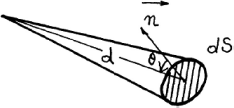
A 1 sr solid angle demarcates on a unit sphere, from the center of this sphere, a surface area equal to 1. For instance, the solid angle, defining a sphere or an observation on the entire space, is 47t sr and the solid angle of the Sun as seen from the Earth is 6 × 10⁻⁵ sr.
A1.2.3. Light intensity
The light intensity is the first physical quantity of visual photometry and is measured in candela (cd). The candela is the luminous intensity unit in the IS. One candela is equal to 1/683 W/sr of a monochromatic source at 540 × 1012 Hz (555 nm). This wavelength corresponds to the yellow–green color.
A1.2.4. Luminous flux
The luminous flux is the second physical quantity of visual photometry; and is expressed in lumens (lm). One lumen corresponds to a flux emitted by a light source with a 1 cd intensity in a 1 sr solid angle. 1 lm = 1 cd/1 sr.
A1.2.5. Illumination
Illumination is the third physical quantity of visual photometry; the lux (lx) is the unit of illumination. One lux is the illumination of an area located 1 m away from a 1 cd light source. 1 lx = 1 lm/m2.
Table A1.2 presents some usual illumination values.
Table A1.2. Usual illumination values
| Night sky | 0.0003 |
| Full Moon | 0.2 |
| 75 W electric lamp at 2 m | 40 |
| Public lighting | 50 |
| Cloudy weather | 15,000 |
| Sunlight in summer at noon | 100,000 |
A1.2.6. Luminance
The luminance is the fourth physical quantity of visual photometry and is the only quantity noticeable by a human eye. The luminance (cd/m2) is the result of the ratio of the luminous intensity of a remote source (e.g. 1 cd) to the value of the apparent area in a given direction (e.g. 1 m2).
Table A1.3 presents some usual luminance values.
Table A1.3. Usual luminance values
| Eye perception threshold | 0.000001 |
| Full Moon | 2,000 |
| White paper in sunlight in summer at noon | 30,000 |
| Projection lamp filament | 20,000,000 |
| Threshold for potential eye injury | 250,000,000 |
| Sun through the atmosphere | 1,600,000,000 |
| Flashlamp | 10,000,000,000 |
A1.2.7. Conversion of visual photometry into energetic photometry
As a principle, photometric values are converted from energy units to visual units by weighting the values with the spectral sensitivity curve of the eye.
For a monochromatic beam (narrow spectral band), the luminous flux Fv (![]() ) at wavelength
) at wavelength ![]() is expressed by the following equation:
is expressed by the following equation:
where:
– Fv(![]() ): luminous flux in lumen;
): luminous flux in lumen;
– Fe(![]() ): energetic flux in watt;
): energetic flux in watt;
– Ke![]() : luminous spectral efficiency;
: luminous spectral efficiency;
– V(![]() ): relative spectral sensitivity of the eye (CIE standard) for wavelength
): relative spectral sensitivity of the eye (CIE standard) for wavelength ![]() .
.
By convention, the curve V(![]() ) is defined from 380 to 780 nm. The maximum sensitivity is at
) is defined from 380 to 780 nm. The maximum sensitivity is at ![]() = 555 nm (maximum of the CIE curve V(
= 555 nm (maximum of the CIE curve V(![]() )) and the Ke value equals 683 lm/W.
)) and the Ke value equals 683 lm/W.
For example, if we are looking for the eye sensitivity value in energy photometry, we follow the following approach. To simplify the calculation, we consider the luminance of a source at 555 nm with an apparent 1 m2 surface area under 1 sr angle.
The luminous flux becomes 0.000001 lm with V(![]() ) = 1 and Km = 683 lm/W.
) = 1 and Km = 683 lm/W.
![]()
The eye sensitivity value in energy photometry (at 555 nm) is 1.5 nW, or about −60 dBm.
For a polychromatic beam (wide spectral band), this relationship is:
![]()
The global visual flux becomes:
And the global energy flow is:
A1.2.8. Bouguer’s relation
The Bouguer’s relation expresses the variation in illumination depending on light intensity, view angle, and distance:
This relation shows that the illumination for a dS surface, located at distance d from a spot-light source I, varies inversely as the squared distance. So, a surface located twice as far from the source has four times greater the area but four times lower the illumination.
A1.2.9. Energy flux or radiated power P
Any optical radiation transports energy at a given speed in the propagation medium. This energy is expressed in joule (J). When it is defined per time unit, it is called energy flux, emitted flux or received power at the considered time. This quantity is the temporal flux of energy and is expressed in watt (W).
In the field of optical wireless devices, this energy flux is characterized by several parameters: average power, peak or maximum power, and operation mode (continuous or pulsed at a determined frequency). To transmit information, it is possible to vary the radiation power or its amplitude. This is then in any case a pulsed mode optical flux, with specific power and energy characteristics.
where:
– P0: average power (W);
– Pc: peak power (W);
– t: pulse duration (s) ;
– T: signal period (s).
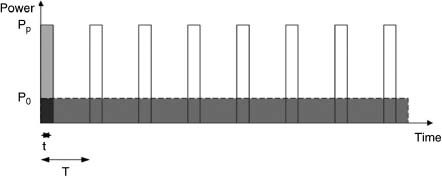
The relationship between the power value in W and dBm is given by:
A1.2.10. Source intensity I
The intensity I for a source in a given direction is the emitted flux from the source per solid angle unit in a considered direction. The intensity is expressed in watt per steradian (W/sr).
If dFs is the flux emitted by the source in the elementary solid angle dΩs, the intensity of the source in this direction is:
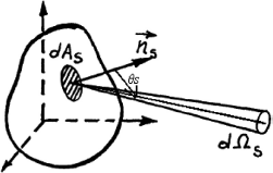
A1.2.11. Luminance of a source L
To characterize the radiation from a source in more detail than the simple knowledge of its flux or intensity, the source can be decomposed into a set of small dAs area elements, independent of each other. The elementary intensity dI corresponding to dAs is defined by the following expression:
![]()
where d2Fs represents the flux radiated by the small dAs area element in the solid angle dΩs.
The energy luminance for a dAs area source is the source intensity per apparent area unit in that direction. Mathematically, this gives:
![]()
where ![]() s is the angle between the local normal to the source and the emission direction, hence:
s is the angle between the local normal to the source and the emission direction, hence:
The luminance energy unit, for which the symbol is L, is the watt per square meter per steradian (W/m2/sr).
A1.2.12. Illumination of a receiving surface E
The surface’s irradiance E at a receiver’s point is the incident energy flux dFr received on a surface element dAr per area unit and limited by the projection dAr.cos![]() r, with
r, with ![]() r which is the angle between the local normal to the reception surface and the emission direction:
r which is the angle between the local normal to the reception surface and the emission direction:
The irradiance unit is the watt per square meter, W/m2.
A1.2.13. Geometrical extent G
In the case of a light beam, the expression for the source luminance can be rewritten as:
![]()
The quantity d2G= dAs cos![]() s dΩs characterized by the source emissive surface and the emission solid angle is called the “geometrical extent” of the light beam from the emitter.
s dΩs characterized by the source emissive surface and the emission solid angle is called the “geometrical extent” of the light beam from the emitter.
Figure A1.7. Geometrical extent of a light beam
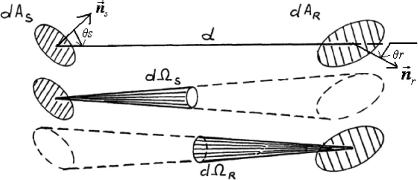
In Figure A1.7, the emission solid angle for this beam is defined by the silhouette of a receiver of elementary area dAr located at distance d from the source:
![]()
We note that the geometrical extent of a beam defined by two diaphragms of areas dAs and dAr located at the mutual distance d can be expressed in two other ways:
where dΩr is the solid angle for the source element dAs as seen from the second diaphragm dAr.
In the case of a light beam, the geometrical extent G is calculated by summing the elementary geometrical extent contributions of all constituted beams.