Chapter Four. Fundamentals of a Digital Model

Before we go too far down the rabbit hole, I want to introduce some of the elements of digital models and the terms you’ll encounter throughout the book. If you have some experience already, you may be inclined to skip this section, but I recommend you at least skim through it just to make sure we’re on the same page. You can think of this chapter as a refresher course of 3D models 101.

A Model’s Anatomy
Digital models can be broken down into three types:
• Polygonal models are made up of a collection of points, edges, and polygons.
• NURBS surfaces consist of a network of curves with smooth surfaces between them.
• Subdivision surfaces are similar to polygonal models because they are made up of points, edges, and polygons but also share some of the benefits of NURBS surfaces, placing them into their own category.
In this section I explain some of the terminology used in the creation of all three types of digital models.
Points
A point, also called a vertex (plural: vertices), is the lowest-level component that makes up a 3D model. Each point exists in 3D space with a specific X, Y, and Z coordinate. Because points alone do not have height, width, or depth, they cannot be rendered.
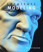
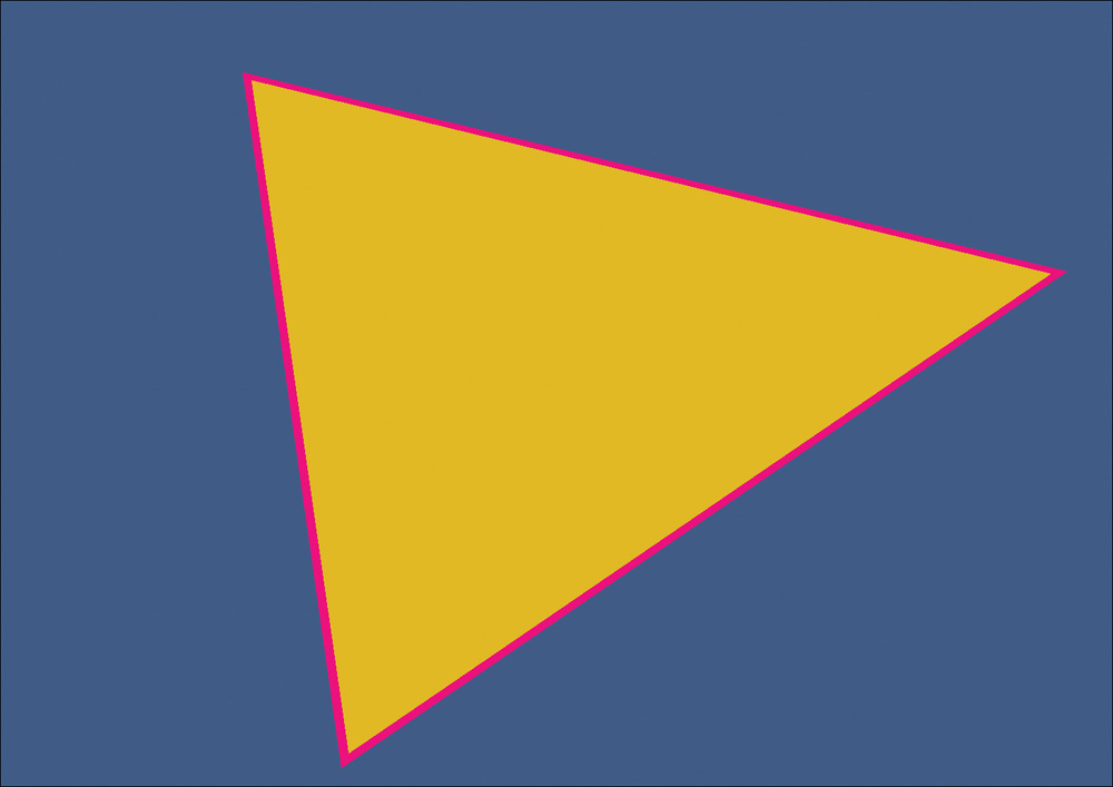
When two points are connected, a line is drawn. When three points are connected, they can become corners of surfaces on a model called a polygon. Without points, there would be no polygons. A triangle, for example, consists of three points and one polygon, as shown in Figure 4.1.
[Figure 4.1] The three points (shown here in pink) define the shape of the triangle and its placement in 3D space.
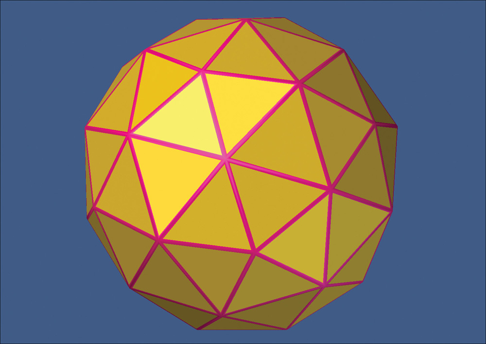
Multiple polygons can share the same points when used on a contiguous (seamless) mesh. The tessellated sphere in Figure 4.2 shows individual points being used to define the multiple polygons that make up the object.
[Figure 4.2] Polygons that share a common edge also share points to define their shape.

Vertex Maps
Every point in an object stores information about its position and rotation, although you normally don’t access the rotational values of an individual point. Points also have the ability to store a variety of additional information using vertex maps. Simply put, a vertex map is information saved to a point.
The most common types of vertex maps include:
• Weight
• Morph
• Color
Texture (UV)
Texture, or UV, maps store texture placement information and are the most common vertex map. UV mapping adds two extra coordinates to the points in your object; those on the U (horizontal) and V (vertical) axes, running horizontally and vertically through the flat plane of the texture map, on which you can paint your texture. UV coordinates are a 2D representation of 3D space. They set up a relationship between a two-dimensional image and the three-dimensional surface the image will be applied to.
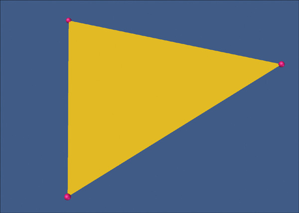
Points can have as many UV maps assigned to them as you’d like. Figure 4.3 shows three UV maps that were created for the Spiderbait character that you can download from my site at www.pushingpoints.com/2011/07/spiderbait-rig.
[Figure 4.3] Three separate UV maps were assigned to the points that make up the character mesh on the right.
Weight
Weight maps store a single value, usually between -100 and 100 (although in some instances lower and higher values are possible). The most common use of a weight map is for defining a bone’s influence on a point when rigging (placing bones and controls to allow a model to be deformed for animation). Figure 4.4 shows positive weight values applied to the points that make up the character’s jaw. When the weight map is assigned to the jaw bone, the points will move when the bone moves. This allows for seamless organic meshes to deform in localized areas.
[Figure 4.4] Weight values assigned to points in the mesh (top) can be assigned to a specific bone (bottom) during the rigging process.

There are far more uses for weight maps than rigging. For example, you can use weights to mask a surface when texturing, influence dynamic simulations over an object, aid during the modeling process, and do much more.
Morph
Morph maps store offset information (alternate XYZ values) for a point’s position and are commonly used for creating morph targets for animation. Figure 4.5 shows several morphs applied to the base mesh. Each morph relies on multiple points being moved to new coordinates, and that information is saved to each vertex.
[Figure 4.5] Morph maps are commonly used to create facial poses for animation.

Similar to weight maps, morph maps have a variety of uses during the modeling and texturing processes.
Color
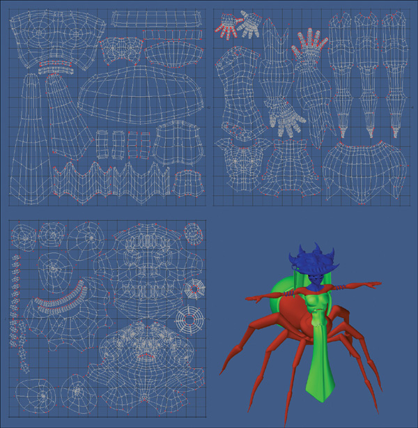
Color maps hold values for Red, Green, Blue, and Alpha (RGBA) color information. I often use color maps on my character models to add color variation to the object’s surfaces, like adding blush to a character’s face. Figure 4.6 shows an example of using a color map to add a five o’clock shadow and some color to a character’s face.
[Figure 4.6] A color map was applied to the character’s face (right) to give the appearance of a five o’clock shadow.
Selection
A selection map, also referred to as a selection set, stores a single state of a point—either selected or unselected. Selection maps allow a modeler to recall a selected group of points quickly and can be extremely useful for defining which points will be affected by dynamic simulations.
Edges
An edge is a one-dimensional line that connects two points in a polygon. Another way to describe edges would be to say that they are the line segments that border a polygon. A triangle, for example, has three edges, three points, and one polygon, as shown in Figure 4.7.
[Figure 4.7] The polygon in this image consists of three edges, shown here in pink.
Similar to points, multiple polygons can share the same edges when used on a contiguous mesh. The tessellated sphere in Figure 4.8 shows individual edges bordering the multiple polygons.
[Figure 4.8] Each polygon shares common edges in this mesh.
Edge weights
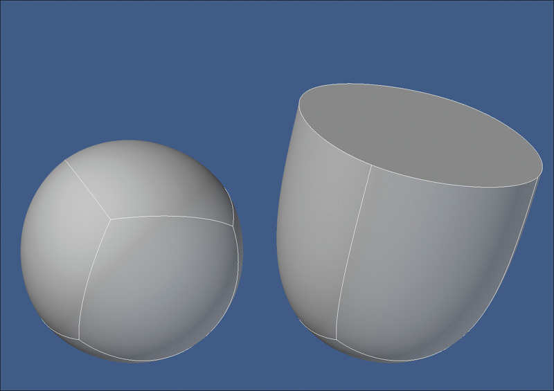
Edge weighting increases or decreases the sharpness of an edge between two subdivision surface (SubDs) polygons, allowing for harder or softer corners without additional geometry being added (Figure 4.9). The main issue with edge weights is that there is no universal, widely supported format that allows you to transfer edge weights from one 3D application to another. In today’s mixed software pipeline, this can be a showstopper. Most modelers I know avoid edge weighting and opt for additional geometry to accomplish the same end goal.
[Figure 4.9] Edge weighting has been increased to 100 percent to the four edges on the top of the SubD object on the left to produce harder edges.
Polygonal Models
Polygons, often shortened to polys and commonly referred to as faces, are geometric shapes consisting of a number of points that define the surface of a 3D object. A polygon is what you actually see in a render, and a typical 3D model will consist of hundreds or thousands of polygons (Figure 4.10).
[Figure 4.10] This head mesh consists of over 6000 polygons.

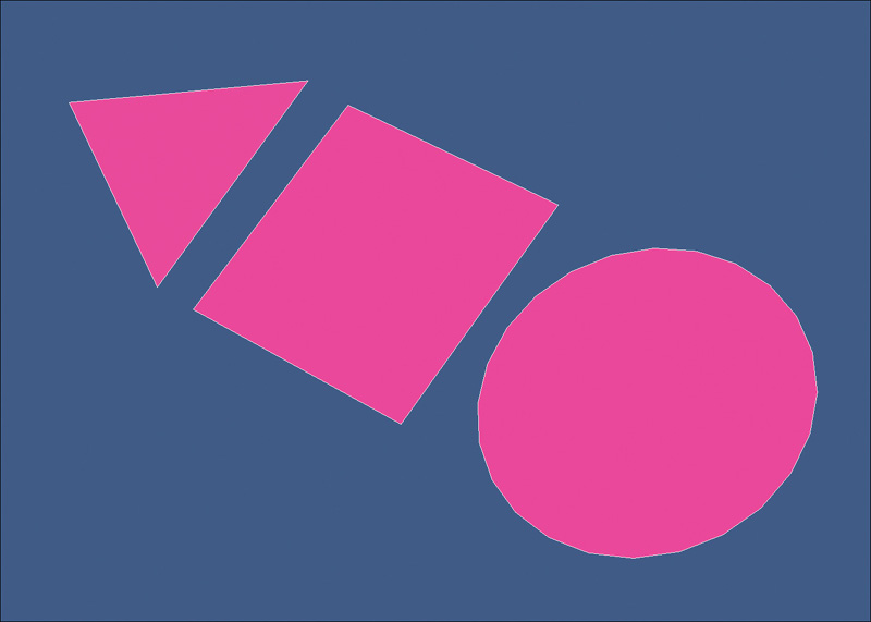
Although some 3D applications allow the creation of one- and two-point polygons, it’s more common that a polygon be made up of at least three points. Three-point polygons are commonly called triangles or tris. Polygons made up of four points are called quads, and a polygon that has more than four points is usually referred to as an n-gon. The term n-gon means a polygon with n sides, where n is the number of the polygon’s sides. For example, a polygon with six sides is a 6-gon. Examples of a triangle, a quad, and an n-gon are shown in Figure 4.11.
[Figure 4.11] Polygons come in all shapes and sizes. The triangle (left) consists of three points, the quad (middle) is made up of four points, and the n-gon (right) is made up of 24 points.
NURBS
A Non-Uniform Rational B-Splines (NURBS) surface is a smooth mesh defined by a series of connected splines, which are polynomial curves. This smooth surface is converted to polygons at render time, so NURBS surfaces can contain an arbitrary number of polygons. NURBS can be converted to polygons or subdivision surfaces and are useful for constructing many types of organic 3D forms because of the minimal nature of their curves. NURBS geometry is smooth by default and doesn’t need to be subdivided to “become” smooth like polygon geometry does.
Non-Uniform refers to the parameterization (defining the parameters) of the curve. Non-Uniform curves allow, among other things, the presence of multi-knots (a sequence of values that determines how much and where the control points influence the shape), which are needed to represent Bézier curves. Rational refers to the underlying mathematical representation. This property allows NURBS to represent exact conics (such as parabolic curves, circles, and ellipses) in addition to free-form curves.
B-splines are piecewise (a function that changes) polynomial curves (splines) that have a parametric representation. Simply put, a B-spline is based on four local functions or control points that lie outside the curve itself.
The best way to understand NURBS is to see them in action. Figure 4.12 shows multiple examples of the splines that define the NURBS surfaces.
[Figure 4.12] Each of these three NURBS surfaces are defined by a series of splines, shown to the left of each object.

NURBS are most commonly used in computer-aided design (CAD), manufacturing, and engineering. Although they were once used heavily for organic objects (see the forthcoming section “Model Classification: Hard Surface and Organic”) in the film and broadcast markets, subdivision surfaces have since replaced them in almost all instances in movies and television.
Splines
A spline is a curve in 3D space defined by at least two points. The most common spline used in digital modeling is the Bézier curve. Bézier curves are used to model smooth curves using far fewer points than a polygonal model would require. Control points make up the curve and can be used to dramatically manipulate the curve with little effort. Also, splines are resolution independent, unlike a polygonal mesh, which can appear faceted when you zoom in close enough to a curved surface.
Splines in 3D applications can be likened to vector curves in software such as Illustrator, Flash, and Photoshop. Splines are similar to NURBS in that they can create a “patch” of polygons that extends between multiple splines, forming a 3D skin around the shape (Figure 4.13), a feature which is extremely useful when modeling. Unlike NURBS, the splines must be converted to polygons before rendering.
[Figure 4.13] The four splines on the left were used to patch the polygonal mesh on the right.

Splines are also useful in many other modeling techniques, including but not limited to, extrusion (adding depth to a flat surface) and cloning (duplicating) along a spline and deforming a mesh based on the curves of a spline.
Subdivision Surfaces
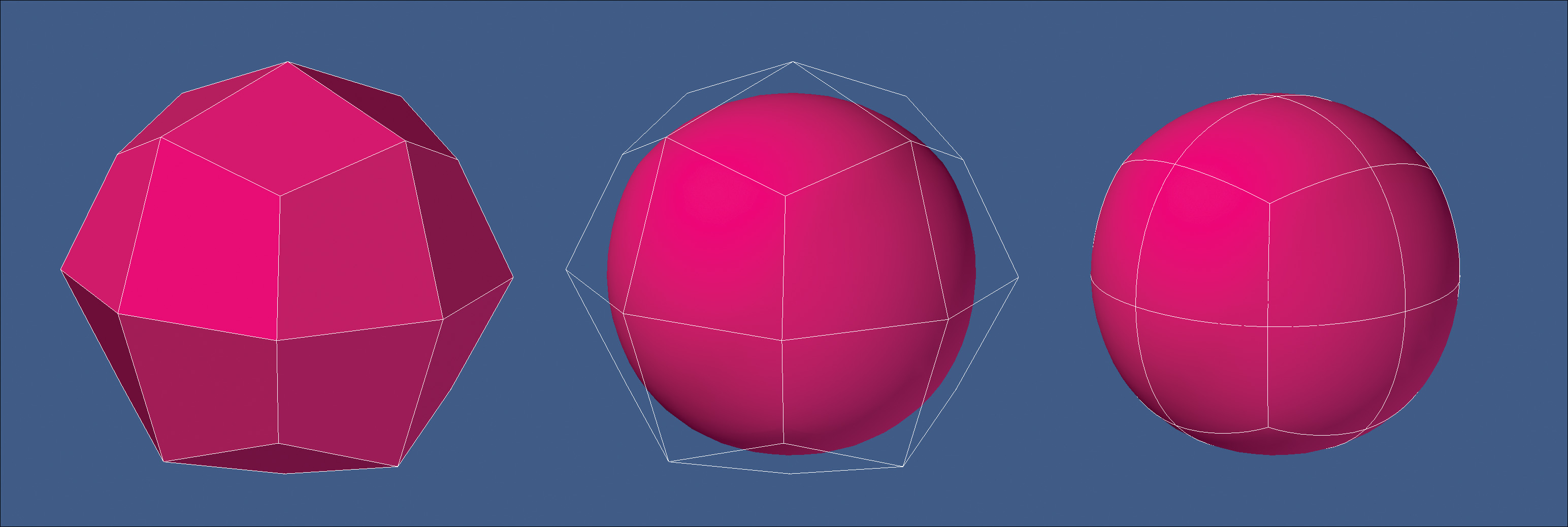
Subdivision surface (SubD) is a refinement algorithm that creates a smooth curved surface from a coarse polygonal mesh (also called a base mesh). This process takes the base mesh and creates a smooth surface using the original vertices as control points, also referred to as the control cage. Figure 4.14 shows the polygonal mesh (left), the control cage (middle), and the resulting SubD mesh (right).
[Figure 4.14] Subdivision surfaces allow you to work with a very light and simple polygonal mesh to create smooth organic shapes.
The number of polygons, or subdivisions, generated from SubDs can be adjusted to a varying level of density, and complex smooth objects can be created in a fast and predictable way from simple base meshes, as shown in the character model in Figure 4.15. This makes SubDs a popular option for most digital modelers.
[Figure 4.15] This character was created with a very simple polygonal mesh (left). But with SubDs applied (middle), a smooth, high-poly mesh was generated (right).

Model Classification: Hard Surface and Organic
When 3D was still in its infancy, digital modelers were usually put into one of two distinct groups based on the type of meshes they constructed. Although the lines have become blurred, these groups still exist today and play a role in how modelers define themselves in the industry. Also, the distinction of the types of meshes a modeler creates makes it easier for studios looking for talent to find the right digital modeler for their specific modeling needs.
Every 3D mesh can be grouped or classified as either a hard surface or organic. What’s the difference? What defines an object as hard surface? What defines an object as organic? So many objects nowadays seem to blur the lines between the two. How would you make a distinction between these classifications?
What may come as a surprise is that if you ask 20 professional digital modelers what the difference between these two classifications is, you’ll receive 20 different responses. I did just that before writing this section of the book and was quite surprised at some of what I heard.
How can something so seemingly clear-cut bring about so many different ways to classify a 3D model? Before coming to a conclusion, let’s explore the most common responses.
Production Driven
Many artists felt that a model would be classified by how it would be used in a production. A static object, such as a stone statue, gas pump, or street sign, would be considered a hard surface object, whereas objects that would deform or animate, such as an animated human character, flag, or animal would fall into the organic category.
The same item could be classified two different ways depending on what the object is called to do for the shot/project. A statue is made of stone and doesn’t usually deform; therefore, it is a hard surface object. But if it becomes a moving statue, as in the world of Harry Potter, it is organic.
Although a gun has moving parts that can be animated, it is still a rigid object, which makes it a hard surface object, unless of course, someone with super human strength comes along and bends (deforms) the barrel—then it becomes organic.
If the mesh is going to deform in some way, it needs to be modeled differently and it should then be classified as an organic object.
Attribute Driven
Some believed that it was a model’s attributes, or what an object looks like, that defined whether it was hard surface or organic. So if the mesh had flowing “organic” curves where any shape could smoothly transform into any other, like a character, ornate piece of furniture, or a sleek sports car, it was an organic mesh.
Hard surface objects would be defined as meshes typically involving tight edges or simpler shapes joining together with distinct edges, even if the shapes were soft or sleek, like guns, power tools, and retro robots.
Also, if the object’s surface attributes were that of stone, metal, or glass, it would fall into the hard surface category, whereas objects made up of living tissue, like animals, plants, and people, would be considered organic.
Construction Driven
One artist defined the two by focusing solely on the modeling aspect. Objects that require a more “organized” topology could be classified as an organic mesh and easily created using “organic” modeling tools and techniques. He believed that organic meshes tend to have more polygons and could benefit from SubDs more than hard surface objects. Hard surface objects don’t require an organized, semi-regular topology and could be created with fewer polygons with less concern about the object’s underlying mesh.
Model Classification Evaluation
Although each of these schools of thought has valid arguments and may work for a particular artist, we simply can’t classify an object based on how it is constructed, will be used in production, or by its appearance. To do that would cause confusion, because every object could find its way into each category.
Take, for example, my dog Jack. He’s a chocolate lab, which is classified as being part of the Canidae family. For the most part, Jack acts like your average dog, wanting to eat, play, and sleep most of the time. He does, however, show attributes of a cat at times, and every now and then he will scratch at the ground after he urinates, like a cat pawing at its litter box. Although this is common in cats, it doesn’t make Jack part of the Felidae family.
Organic modeling goes beyond the fact that the shape of the model is rounded. Many hard surface objects have organic shapes, like cars, cell phones, and robots, whereas organic objects can have rigid shapes like rocks, insects, and crustaceans. Industrial design has moved more towards organic shapes over the years, and the entertainment industry is taking things that were traditionally hard surface, static objects and deforming them in animation—having gas pumps dance in commercials, for example.
Also, modeling something to perform well when animated is just good modeling technique and shouldn’t determine whether something is hard surface or organic. For example, look at a mesh sculpted in ZBrush, or modeling with metaballs or voxels. You can create something very organic, but these modeling techniques will make the model nonconducive to animating. Would that then be considered hard surface modeling? Of course not.
Most modelers don’t limit their tool and technique use based on whether a model is organic or hard surface. Generally, they use good modeling techniques, which include building a model that’ll hold up if deformed, even if it’s not intended to, and apply those same techniques regardless of whether the model is hard surface or organic.
You hear the terms hard surface and organic modeling all the time in the 3D modeling community, and artists are often defined as one or the other. If you make mostly characters meshes, you are an organic modeler. If you make more architectural or mechanical objects, you are a hard surface modeler. I usually describe myself as an organic character modeler, but it is simply not that straightforward, because I create products and vehicles that are defined as hard surface too.
So back to the point: What’s the difference between hard surface and organic models, and how do we define the two? I suppose, essentially, there is no difference at all, and it is a question of semantics. For the purposes of this book (and based on my personal philosophy), I use the following distinction: Characters, creatures, plant life, and more naturalistic environments are organic models, and architectural environments, vehicles, and mechanical products are hard surface. This is very loose as a definition, and as I’ve tried to emphasize, the lines between the two are indeed very blurred.
Hard surface
Hard surface objects are anything man-made or constructed. Architectural structures, vehicles, robots, and anything machined or manufactured could fall into this category. The robots from FunGoPlay’s Grid Iron Gladiators (www.fungoplay.com), shown in Figure 4.16, would fall into the hard surface category.
[Figure 4.16] Although these robots have smooth organic shapes, they still fall into the hard surface category.

Organic
Organic models are subjects that naturally exist in nature. This would include humans, animals, plants, trees, rocks, boulders, terrains, clouds, and even lightning bolts. The nonplayer characters that roam the world of FunGoPlay (Figure 4.17) would be considered organic models.
[Figure 4.17] These characters from FunGoPlay would be classified as organic models.

Model Styles
As with a model’s classification, a mesh usually has a specific style associated with it. A style refers to a specific philosophy, goal, or look. Realism, impressionism, abstract expressionism, and surrealism are common styles found in traditional art. Although a digital model could easily fall into any of the traditional art styles, the 3D industry usually places them into one of two different model styles: photo-real and stylized.
Photo-real
When a model depicts an object with realistic accuracy, the term photo-real is applied. Digital artists use photographic reference and their observation skills to transfer the realistic properties to the details that make up their models.
It’s important to understand that the subject matter is not required to be a real-world object, like a car, human, or architectural structure. Models of robots, dragons, and other fictional subjects can also be modeled in a photorealistic style using real-world reference as a guide.
Stylized
When a digital model consists of artistic forms and conventions in a non-realistic style, it is referred to as a stylized model. Simply put, a stylized model is one that is not photo-real. Cartoon characters and environments are classic examples of stylized models.
The best stylized modelers I know still gather and use just as much real-world reference material as a photo-real modeler. The only difference is how they interpret it and apply that information to the model.
Choosing a Style
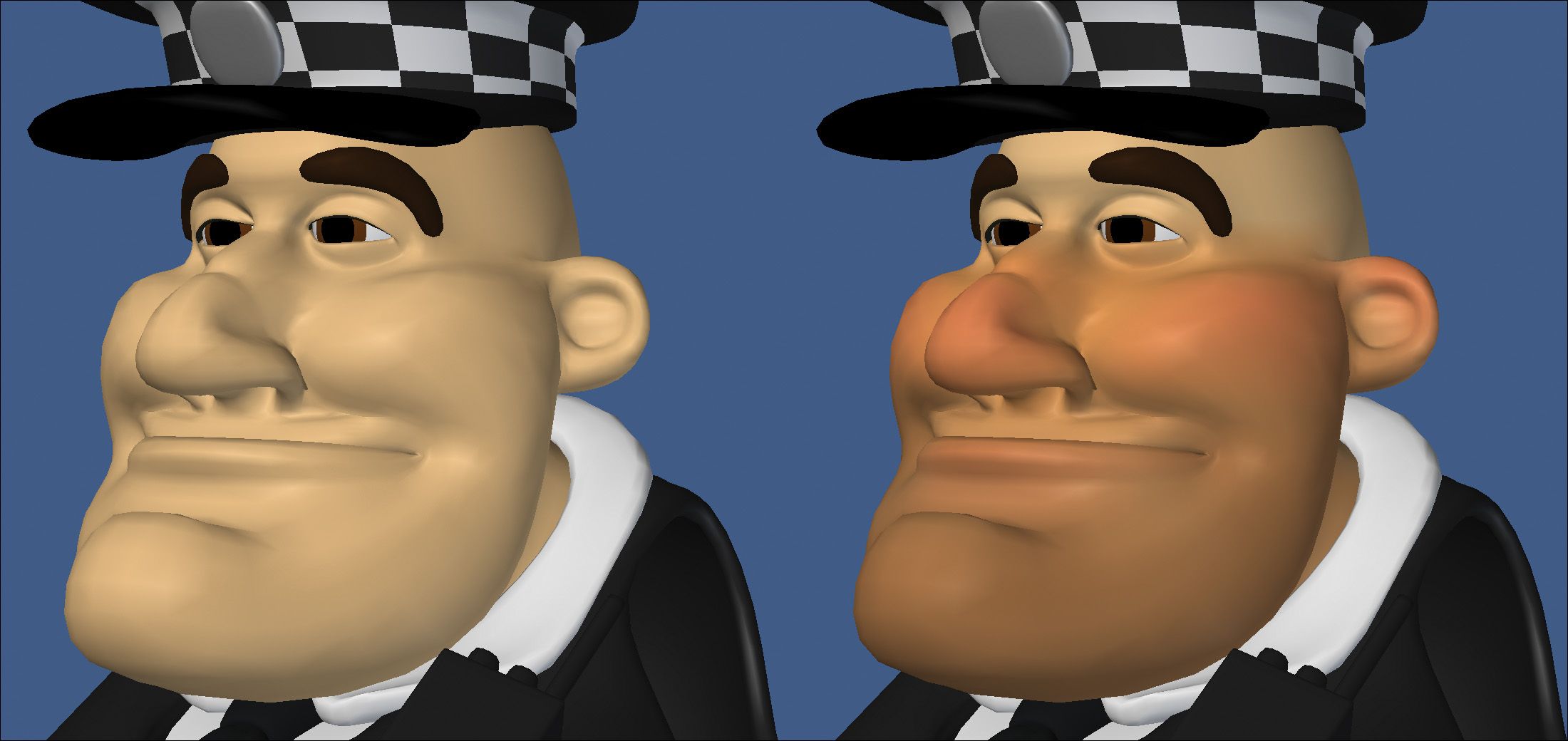
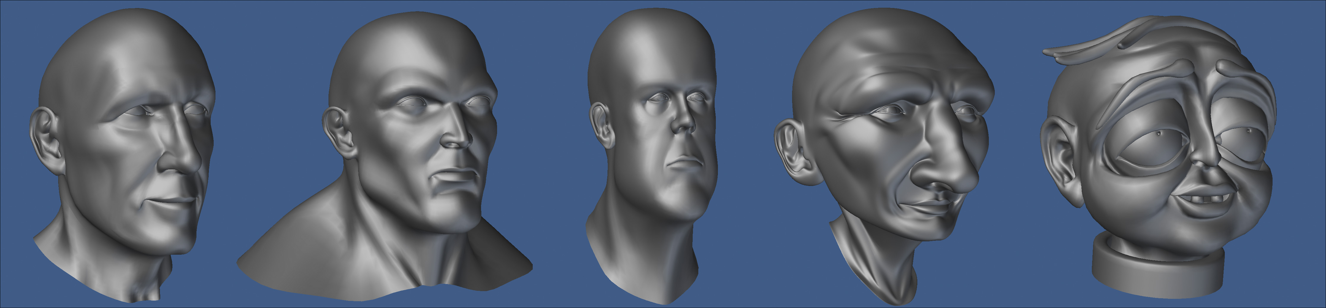
Although many artists would argue otherwise, I don’t find either style of modeling to be more difficult than the other. Both styles require the same attention to detail, and the same care needs to be put into the poly-count and topology of the mesh. At the end of the day, the only real difference between the two styles is where the points are arranged on the model, as shown in the head models in Figure 4.18.
[Figure 4.18] Each of these head models consists of the same elements, but only the head on the far left would be classified as photo-real.
Most artists gravitate towards a particular style. I prefer creating stylized models and creating meshes that have otherworldly proportions and attributes, but I also tackle photo-real models on a regular basis. My modeling toolset and techniques don’t change depending on the style of the mesh I’m tasked with. Digital modelers’ goals should be to hone their observational skills and to have the ability to work across styles.
Learning to work in both styles will only enhance your ability in the style of your choice and will open up more opportunities to you as a professional modeler.