Chapter Nine. Modeling a Realistic Head

Chances are good that at some point in your digital modeling career you will be tasked with creating a 3D model of a realistic head. It might be used for a live-action television series in need of a CG stunt double, for an animated game cinematic, or any number of projects that require a photorealistic 3D human head.
The biggest challenge when creating a realistic head model is that just about everyone can spot a bad CG face from a mile away. This is because we see faces every day. Reference and observation, once again, are key to the success of re-creating a human head in 3D.
In this chapter, I’ll walk you through creating a realistic head with these four main objectives in mind:
• Using subdivision surfaces
• Matching reference material
• Building a clean mesh that is ideal for animation
• Making extensive use of the edge extend (extrude) build out modeling method

Choosing a Method: Edge Extend vs. Box Modeling
There really is no one technique that you have to use when creating any digital model. That said, the two most popular methods for creating a character head are box modeling and the edge extend build out method. With box modeling, I would start with a primitive object (box, ball, disc, and so on) and would work on the primary details first, like the overall head shape. I would then build in the finer secondary and tertiary details. Using the edge extend method, I would start with the tertiary details, like a fully detailed eye, and build out additional geometry from there. To create the realistic head used as the example for this chapter, I chose the edge extend method.
It’s important that I take a minute to explain why I chose the edge extend method of modeling for this particular model, because I don’t want you to get the wrong idea. I’ve read quite a few articles and forum threads, written by industry professionals, that would lead you to believe that the edge extend technique is the only option when building a realistic head, and that other methods, such as box modeling, are not accurate enough. Also, some would say that you can tell the difference between a head that has been created using the build out method and one that has been created using other methods. This couldn’t be further from the truth.
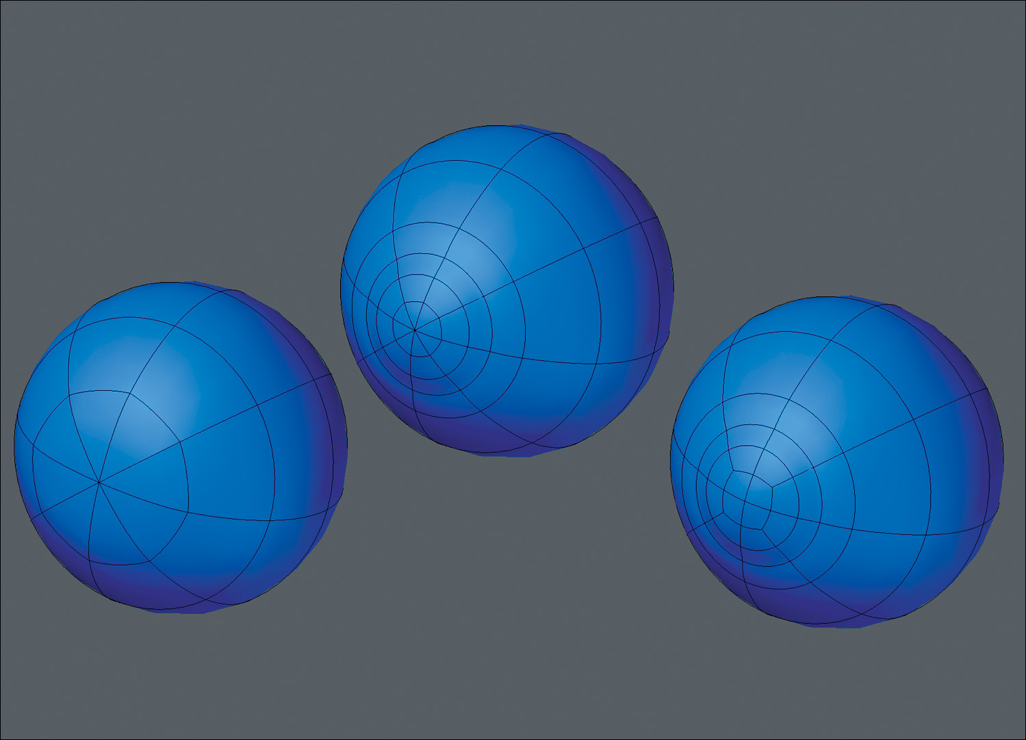
I’ve used the box modeling method for creating more realistic heads in my career than any other technique. Figure 9.1 shows a couple of head models created using the box modeling technique. I’ve even tried my hand at other methods of modeling a head, and regardless of the technique used, they all delivered similar results. There is really no way to tell how a model was created. The only attributes of the model that a discerning eye can recognize is whether or not it matches the reference and whether it’s a clean mesh.
[Figure 9.1] The box modeling method was used to create these two head models.

Why have I chosen the edge extend method? I tend to choose the edge extend method when I’m in a pinch and short on time. It’s by far the fastest way I know to create a production-ready, realistic head. It is also the easiest method for someone new to modeling to learn.
For the walkthrough in this chapter, I wanted to use a young female model, because I find female models to be more challenging than male models. Most female faces are smooth, whereas most male faces are on the rougher side. With a male model, you’re more likely to get away with a mesh with dents and dings because the features can add character to a male face, but on a female model that same texture can look unattractive and distracting.
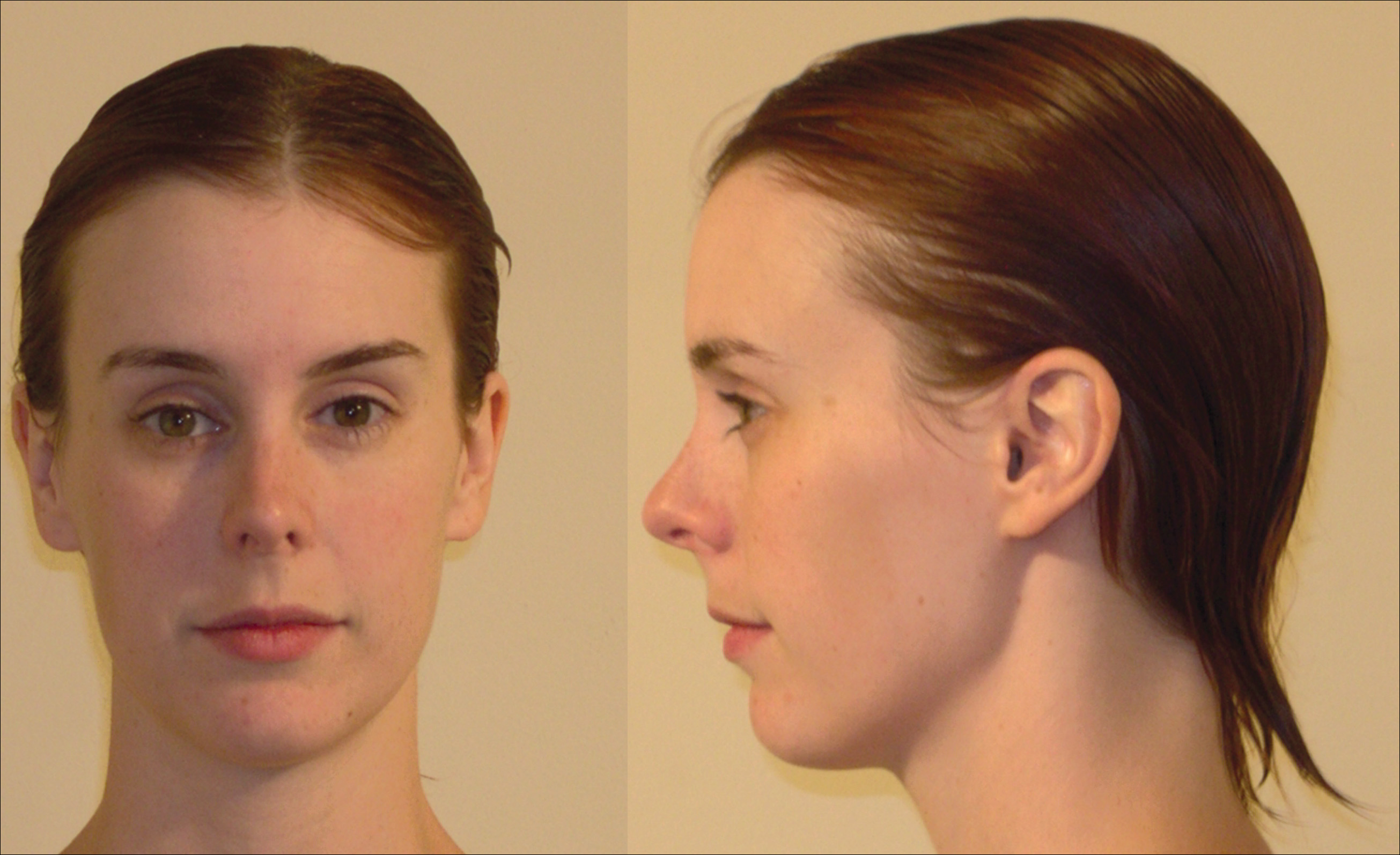
My friend April Warren (www.aprilwarren.com), shown in Figure 9.2, is the subject for this chapter and is an ideal candidate for us to reference.
[Figure 9.2] Actress and digital artist April Warren will be our subject for this chapter.

Using Reference
April was kind enough to supply not only great front and side reference snapshots, but she went the extra mile and delivered a collection of photos showing a range of expressions (Figure 9.3). These shots are a great resource and demonstrate why good poly-flow is essential to a realistic head that will animate. These facial expressions are driven by motions or positions of the muscles of the face. When we create proper poly-flow in our 3D meshes, we can mimic the movement of these muscles. Keep this in mind when I walk through the process of building the areas of the face that you see undergoing the most change in these various expressions.
[Figure 9.3] Facial expressions are an important channel of non-verbal communication and play a substantial role in character animation.

Preparing the Background Templates
After a good study of the reference images, the next step was to prepare the front and side images that were used as the background templates for modeling on top of. This preparation required using Photoshop to scale and rotate the two images in order to line up key areas like the corners of the eyes, tip of the nose, corners of the mouth, and chin (Figure 9.4).
[Figure 9.4] Matching the front and side images is an important step before modeling begins.
It’s common that the ears remain a little off due to camera lens distortion and the fact that ears sit closer to the camera in a side-view photo. As you can see in Figure 9.4, the bottom of April’s ears line up, but the top of the ear in the side view is higher than the front. When possible, it’s ideal to use a long lens to reduce this type of distortion, but because these photos were taken with a simple point-and-shoot camera, I just needed to compensate for the difference when I modeled the ears. To do this, I focused on the side-view reference when modeling the ear and overlooked the fact that it wouldn’t match the front-view reference. Once the final mesh was created, I eyeballed the difference and chose an ear height that looked good.
Taking Advantage of Symmetry
Taking advantage of symmetry on a mesh like this means only having to model one half of the head, and can also make for more efficient UV mapping, morph target creation, rigging, and more. If you look at the front view of April in Figure 9.4, you can see a slight difference between the two sides of her face. Using Photoshop, I mirrored the (screen) right side of her face over to the (screen) left (Figure 9.5).
[Figure 9.5] Mirroring a person’s face may look alien, but it can save valuable production time when modeling.
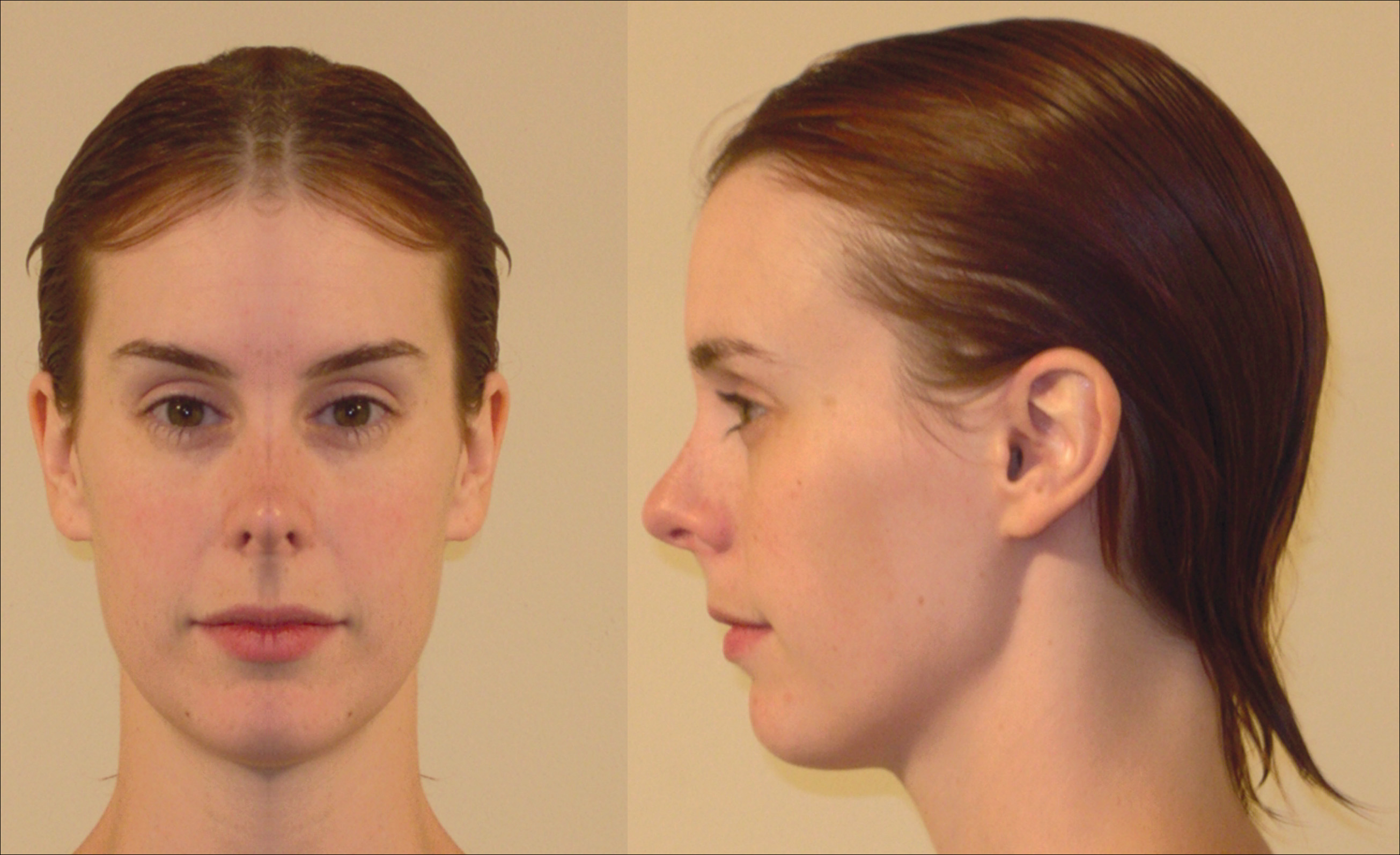
The new reference now looks a bit alien, and it’s important to understand that no real-world human has a perfectly symmetrical face. CG human models with symmetrical faces can stand out as not being realistic and are, unfortunately, commonly seen throughout the industry. The trick is to create an asymmetrical model and use an asymmetrical morph during the rigging phase. This allows for all departments to take advantage of symmetry while not losing the asymmetrical qualities of a real-world person in the final render.
Modeling the Head’s Components
With the reference prepped and a modeling method chosen, I was ready to start modeling. The six main components that I needed to tackle on the mesh were:
• Eyes
• Nose
• Mouth
• Ears
• Jawline
• Rest of the head
Using the edge extend technique, or any form of build out, allows you to start modeling any area of a model. But I find the eyes to be the best place to start when modeling a human face.
Eyes
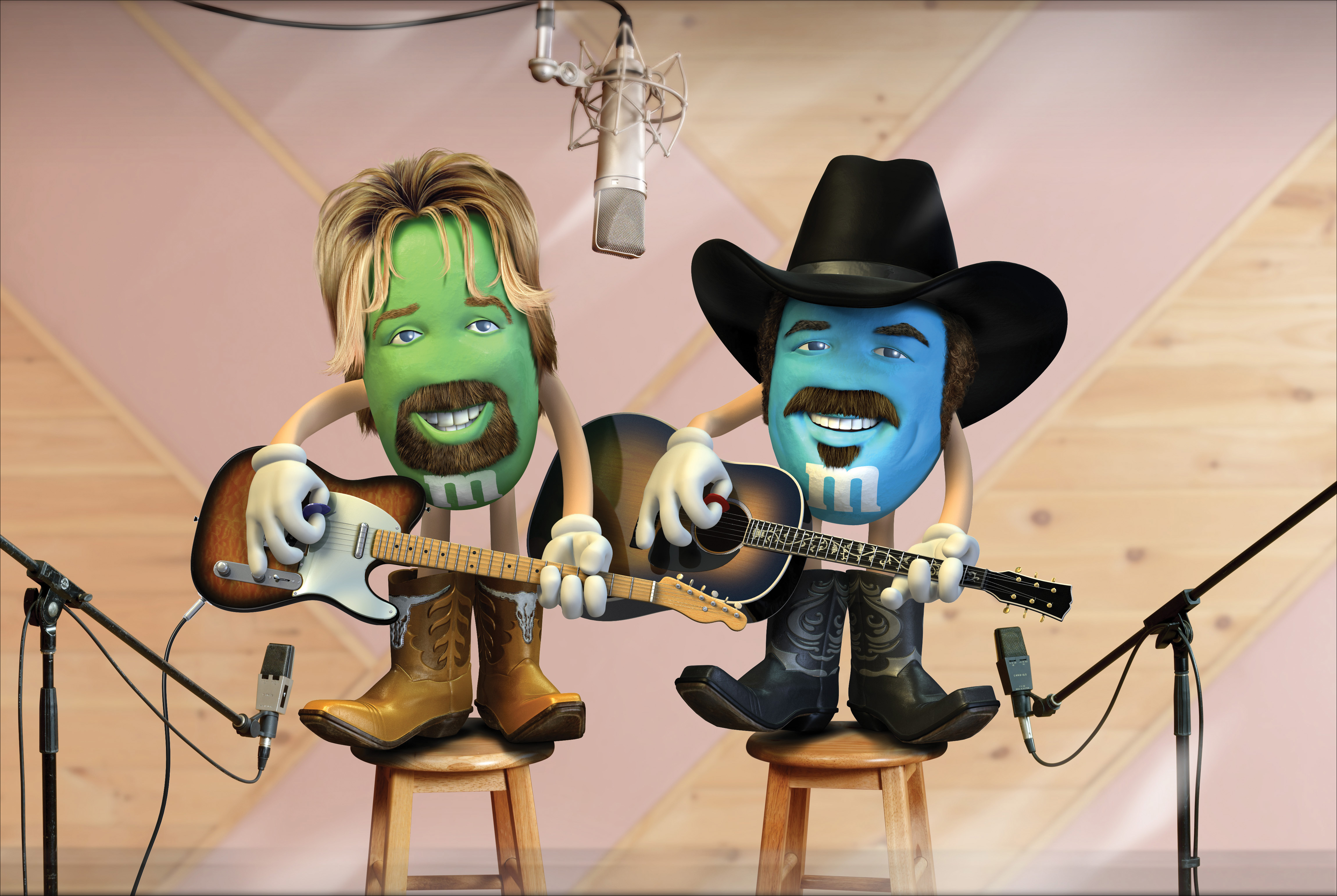
If you don’t match the eyes, it’s nearly impossible to create a likeness of a particular person. If the eyes on a CG model are identical to the reference, other areas can be close enough and you can usually get away with it. I used this knowledge to my advantage when modeling a series of celebrity M&M’s, like the Brooks and Dunn M&M’s shown in Figure 9.6, because they required a likeness without having a nose, ears, or other key defining attributes that usually help capture a likeness.
[Figure 9.6] These celebrity M&M’s relied on the eyes to capture the likeness.
Eyeballs
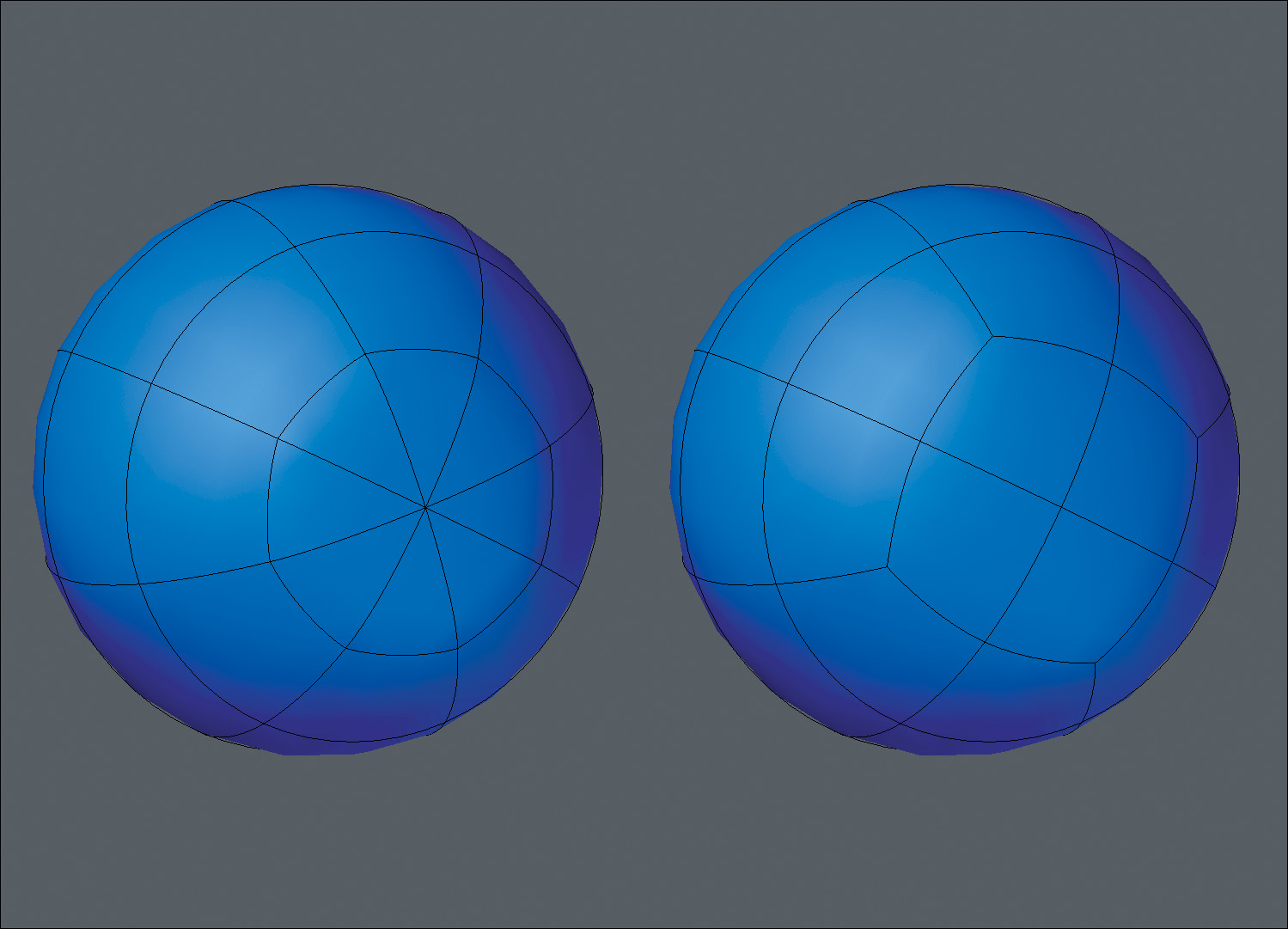
Many artists begin modeling a character’s face without starting with an eyeball mesh, which I find to be less efficient than having an eyeball in place to conform the eyelids to. Although I used the edge extend technique for modeling the head, I cheated and built the eye out of a low-poly sphere primitive. Because I took advantage of subdivision surfaces (or SubDs, which we defined as a refinement algorithm that creates a smooth, curved surface from a coarse polygonal mesh), I limited the amount of sides and segments that made up the sphere to keep a low poly-count. Figure 9.7 shows the back of the eyeball.
[Figure 9.7] Keeping the poly-count low on a character’s eyeballs will help increase render times later during the production.
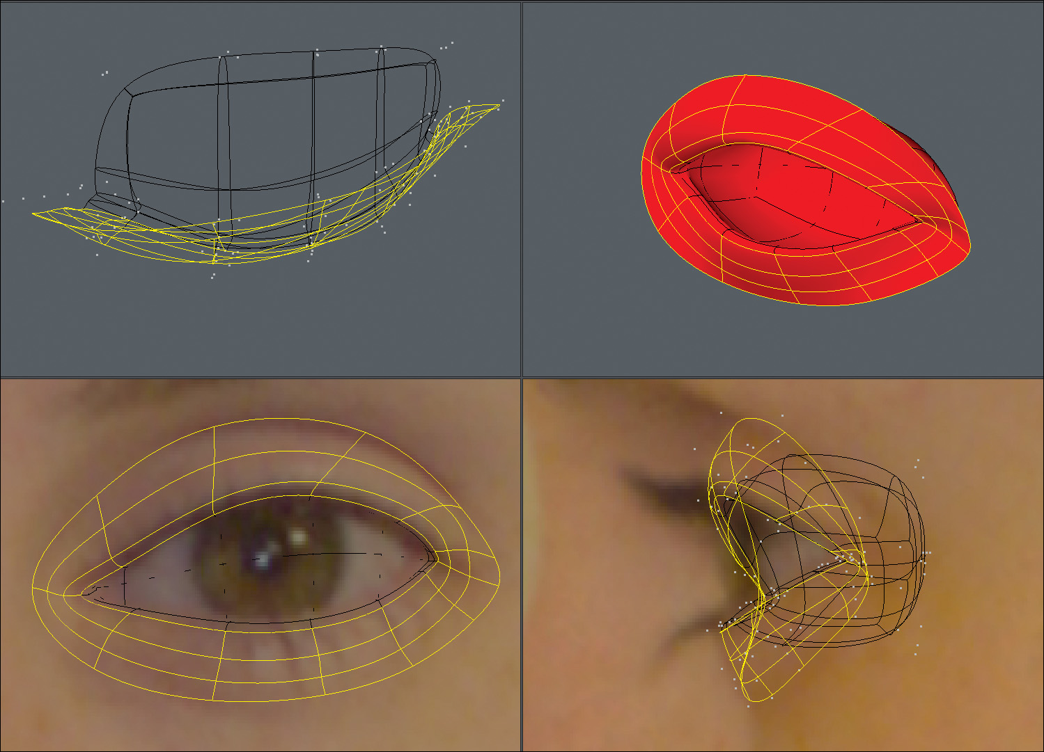
After I created the eyeball base mesh, I lined it up with the background images. For the front of the eyeball, I selected the eight triangles, flattened them, and performed five bevels to create the shape of the iris and pupil. When I was happy with the shape, I merged the eight triangles into four quads like I did on the backside. Figure 9.8 shows the results of these steps.
[Figure 9.8] Modeling the iris flat and the pupil indented will produce much more realistic renders than a perfectly round eye.

One last element needed to be created for the eyeball mesh to be finished, and that was the cornea geometry. Using a slightly larger sphere, I went through the same steps as before, but this time I beveled the polygons on the front of the mesh outward to create a slight bulge for the cornea (Figure 9.9). When textured, this geometry will be made transparent with reflective and refractive properties, giving the appearance of a shiny, glasslike surface at render time. For the rest of this walkthrough, however, we will shelve this portion of the mesh because it’s not required for the remaining steps.
[Figure 9.9] The cornea geometry will be made transparent and reflective with a level of refraction to give the eyes a glasslike quality.
Eyelids
With the eyeball created, I moved forward by creating the eyelid area of the face. I started with a flat plane that I sliced into eight polygons. I wasn’t picky about where I made the cuts because I knew I would eventually adjust the points, conforming to the shape of the opening of the eye. Using the reference images and the eyeball as guides, I moved the points to create an arched leaf shape (Figure 9.10).
[Figure 9.10] Taking special care with point placement early on will save clean up time later in the modeling process.

Before I started edge extending, I cheated again by not edge extending and instead beveled the geometry four times to create the inner ridge of the eyelid as well as something that I refer to as the eye-sack (Figure 9.11). The eye-sack is just extra geometry behind the eyeball that can come in handy later in the modeling process, as you will see. It is also necessary if you plan on creating a 3D print of the mesh, because you can’t have open edges on a mesh when printing.
[Figure 9.11] Beveling allows you to quickly create the inner portions of the eyelids.

It was finally time to start the edge extending. I selected the open edges around the eye and extended them three times, creating the eyelids (Figure 9.12). It’s important to create enough edge loops to be able to properly close the eyelids during animation but not so many that it causes unwanted creases. Also, it’s tempting to continue extending the edges, but it’s important to reshape the newly created geometry first, because it will save time in the long run.
[Figure 9.12] Using the rule of three, I made sure I had enough segments to allow the eyelids to close properly.
A close look at the reference material shows the lacrimal caruncle—the small mass located at the inner corner of the eye. I wanted this mesh to be realistic, so I needed to re-create this mass of skin. I even add the lacrimal caruncles to most of my cartoon character models as well and have found that most people spot the detail and comment on it favorably.
I selected the inner corner polygons and beveled them to generate localized detail. I wanted to also take advantage of the extra polygons along the edge, so I deleted the existing corner polygons shown in purple in Figure 9.13, and reshaped the newly created geometry.
[Figure 9.13] Adding the lacrimal caruncle gives a higher level of realism to a model’s eyes.

Eye socket
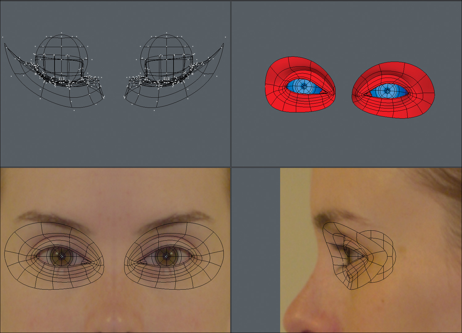
I extended the open edges of the eyelids two times to create the eye socket area of the face. When I was happy with my point placement, I mirrored the entire mesh across the X axis. The results are shown in Figure 9.14.
[Figure 9.14] Mirroring and working with symmetry allows you to create character meshes in half the time.
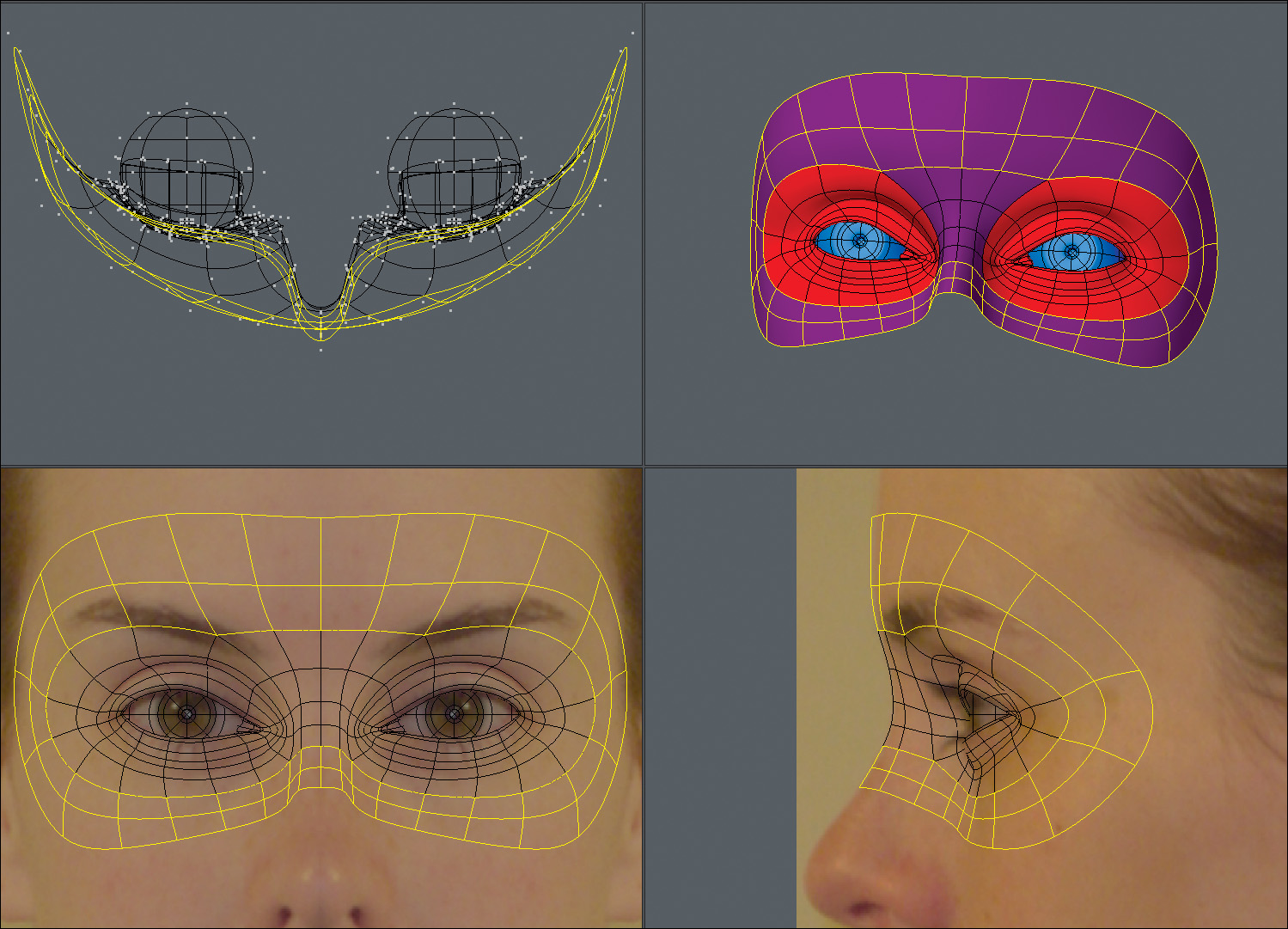
Eye mask
Connecting the inner edges of the eye sockets with four rows of quads allowed me to construct the root of the nose. I then extended all of the open edge twice to create what I refer to as the eye mask, or Zorro mask (Figure 9.15). At this point, I took a few minutes to make sure I was happy with the eye region of the face. It’s always important to go back over the mesh from time to time to ensure that you’re still on target.
[Figure 9.15] Always take time to go back over your mesh when you’ve completed the eye mask region and make sure you’ve captured the reference’s likeness.
Nose
For the nose region, I started by extending the bridge of the nose several times, making note of where I would need extra rows for future use. I then extended geometry around the wings of the nose. I bridged the wings to the bridge with three rows and then closed the hole that was generated by creating the necessary quads. The results are shown in Figure 9.16.
[Figure 9.16] Creating proper flow around the wings of the nose will help define the wings and allow for proper deformation.

I then extended three rows of polygons off the tip of the nose to create the septum, and extended the edges around the nostrils and wings of the nose. I extended the end edges of the nostrils one time and then connected them to the end row around the wings with a single polygon, which gave me the results shown in Figure 9.17.
[Figure 9.17] Having a row of polys flow around the wings and into the nostril gives a natural look to the mesh that holds up well during animation.
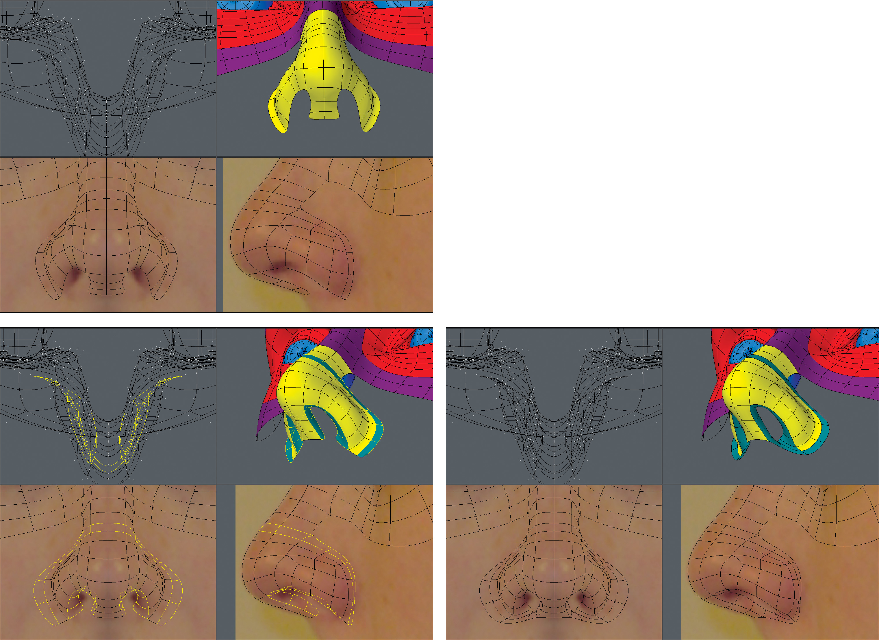
Extending the inner nostril edges again allowed me to then create new polygons to close off the inside of the nose, as shown in Figure 9.18.
[Figure 9.18] Although most camera angles won’t reveal the inner nostril, it’s always a good idea to close off the geometry.

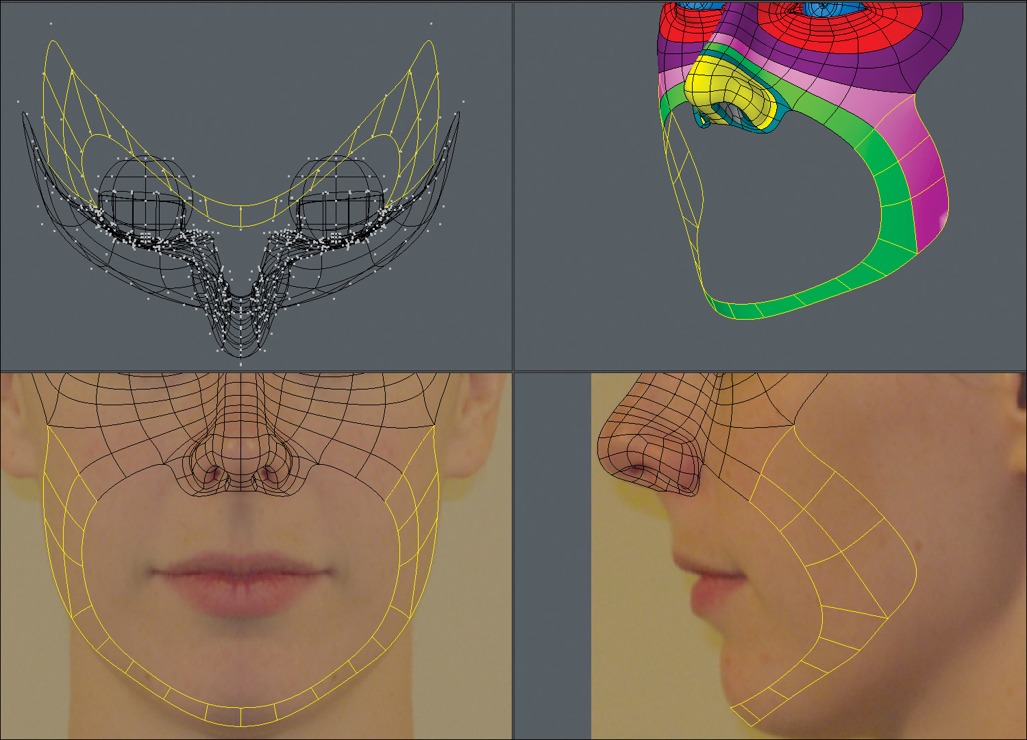
Laugh Line
Before moving on to the mouth, I like to make sure I get a solid laugh line in place. A proper laugh line edge loop should border the mouth, run around the wings of the nose, and cross over the bridge of the nose. This region of the mesh is often overlooked by modelers, leading to undesirable results when a character makes extreme expressions with his or her mouth. A strong laugh line is key to successful deformations, so it’s always a good idea to get it in place early on. Figure 9.19 shows the progression of extending the laugh line geometry.
[Figure 9.19] The laugh line poly flow plays a substantial role in good deformations through a wide range of a character’s facial expressions.
Mouth
Many modelers will continue to extend off the nose to create the mouth, but I’ve found that it’s much more efficient to build the mouth separately in the same fashion as I built the eyes. I started with a flat plane, sliced it into 12 polygons, and pushed points to shape the geometry to the reference images. The result of this process is shown in Figure 9.20.
[Figure 9.20] Using a separate piece of geometry for the mouth produces results quicker than extending from the nose region.

I beveled the mouth polys six times to create the lips and the inside of the mouth. Each time I beveled, I adjusted the points to conform to the reference. It’s important to not be in a rush when adding new geometry and to take the time to refine the mesh as you go. Figure 9.21 shows the result of these six bevels with refinement.
[Figure 9.21] Similar to the eye-sack technique, beveling the mouth geometry to create the lips is a trick I’ve used for years and saves production time.
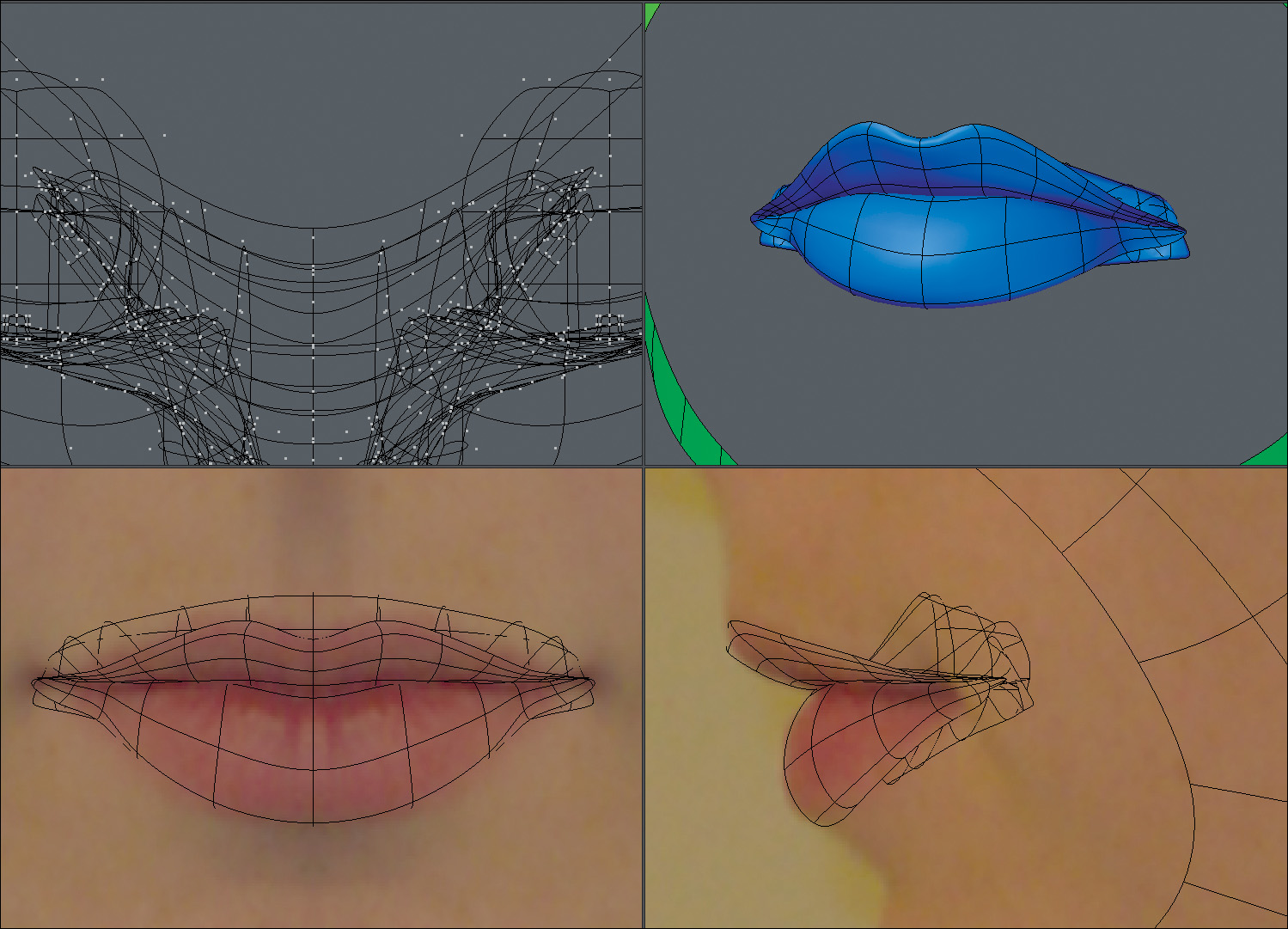
With the lips in place, I selected the open edges that made up the mouth and extended them three times. These edge loops are important because they will allow for smooth deformations to take place around the mouth.
I connected the six polygons located in the top center to the nose region of the face, extended the remaining open edges of the mouth twice, and connected the new geometry to the bordering polygons to create a seamless mesh. The results are shown in Figure 9.22.
[Figure 9.22] The edge loops around the mouth allow for clean deformations in that region when animated.

Jawline
When a character opens his or her mouth, it requires the entire jaw to hinge open. I’ve found that creating a row of polygons that follows along the jawline, although not 100 percent necessary, can be a safe bet for good deformations. So, I extended jawline polygons off of the laugh line and then extended the row up to the ear.
With the jawline in place, I completed the area by extending polygons and connecting them to their neighboring polys. Figure 9.23 shows the results.
[Figure 9.23] Creating poly flow along the jaw can help define the jawline. Extending polygons and connecting them to their neighboring polys finishes off that region of the face.

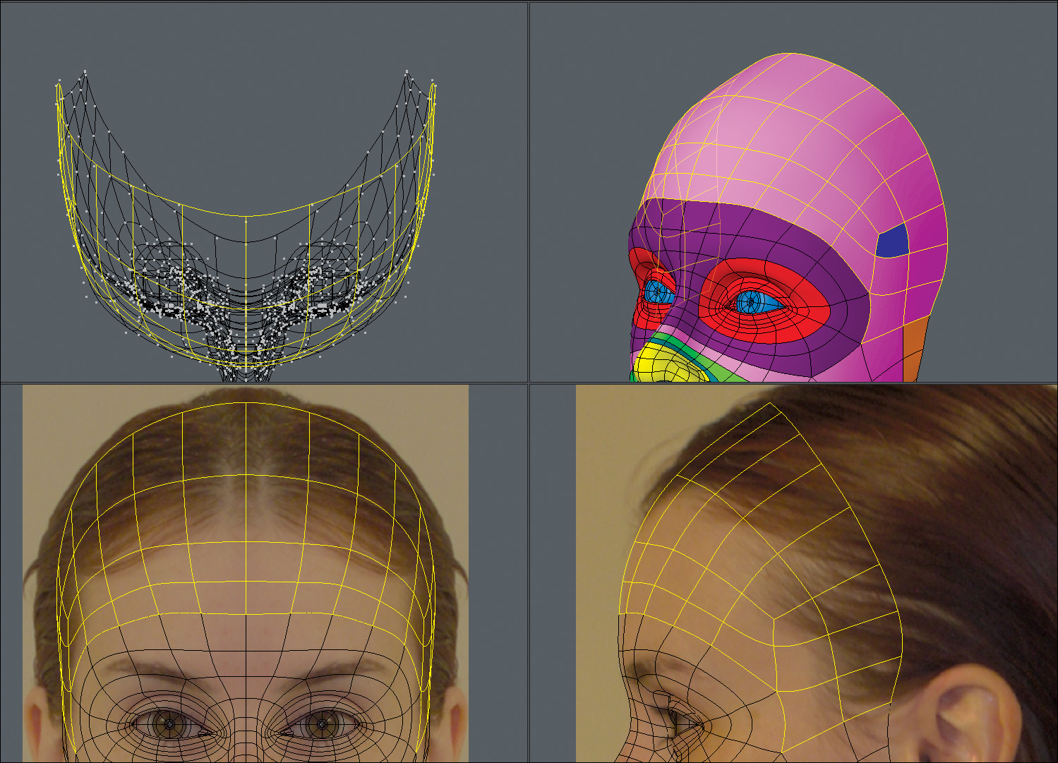
Before moving on to the ear, I wanted to finish off the face mask, also referred to as the death mask region of the face, by adding a forehead. I simply extended off the eye mask edges and connected to the jawline. Note that the polygon shown in blue in Figure 9.24 was used to reduce the forehead geometry from flowing into the jaw area. Although I only saved one row of polygons, every polygon counts at render time, so avoid any unneeded geometry whenever possible.
[Figure 9.24] Terminating rows of geometry where it is not needed allows for localized detail and a cleaner mesh.
Ears
Many artists struggle with modeling ears, but I think it has nothing to do with the difficulty and everything to do with psyching themselves out before they begin. If it helps, don’t think of the shape as an ear but simply as an organic form that has specific shapes. I always start modeling an ear the same way when using the edge extend method and used the same technique on this mesh. I started by mapping out the outer rim of the ear (the helix), as shown in Figure 9.25).
[Figure 9.25] Starting with the helix allows you to define the borders of the ear.
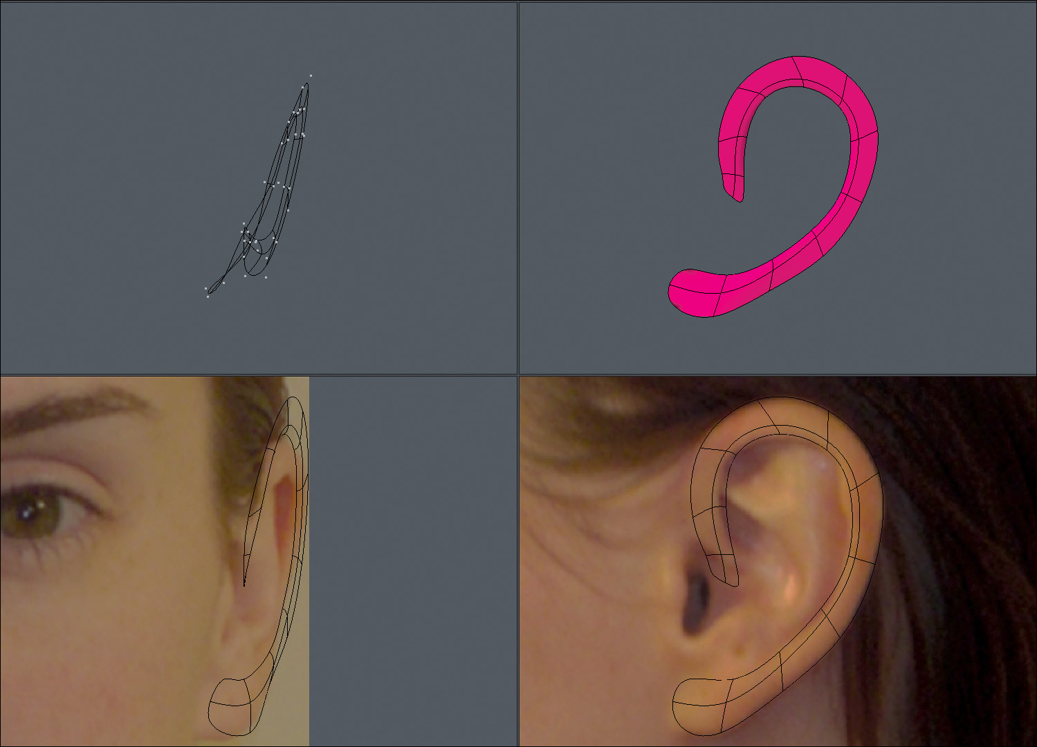
With the helix in place, I spent a few minutes patching in the inner ear based on the reference. Polygon flow is far from important when dealing with the inner ear, but sticking to an all-quad mesh is always desirable. Figure 9.26 shows the inner ear base mesh completed.
[Figure 9.26] Poly flow is not important when creating the inner polygons of the ear because it doesn’t undergo the same level of deformation as the face.
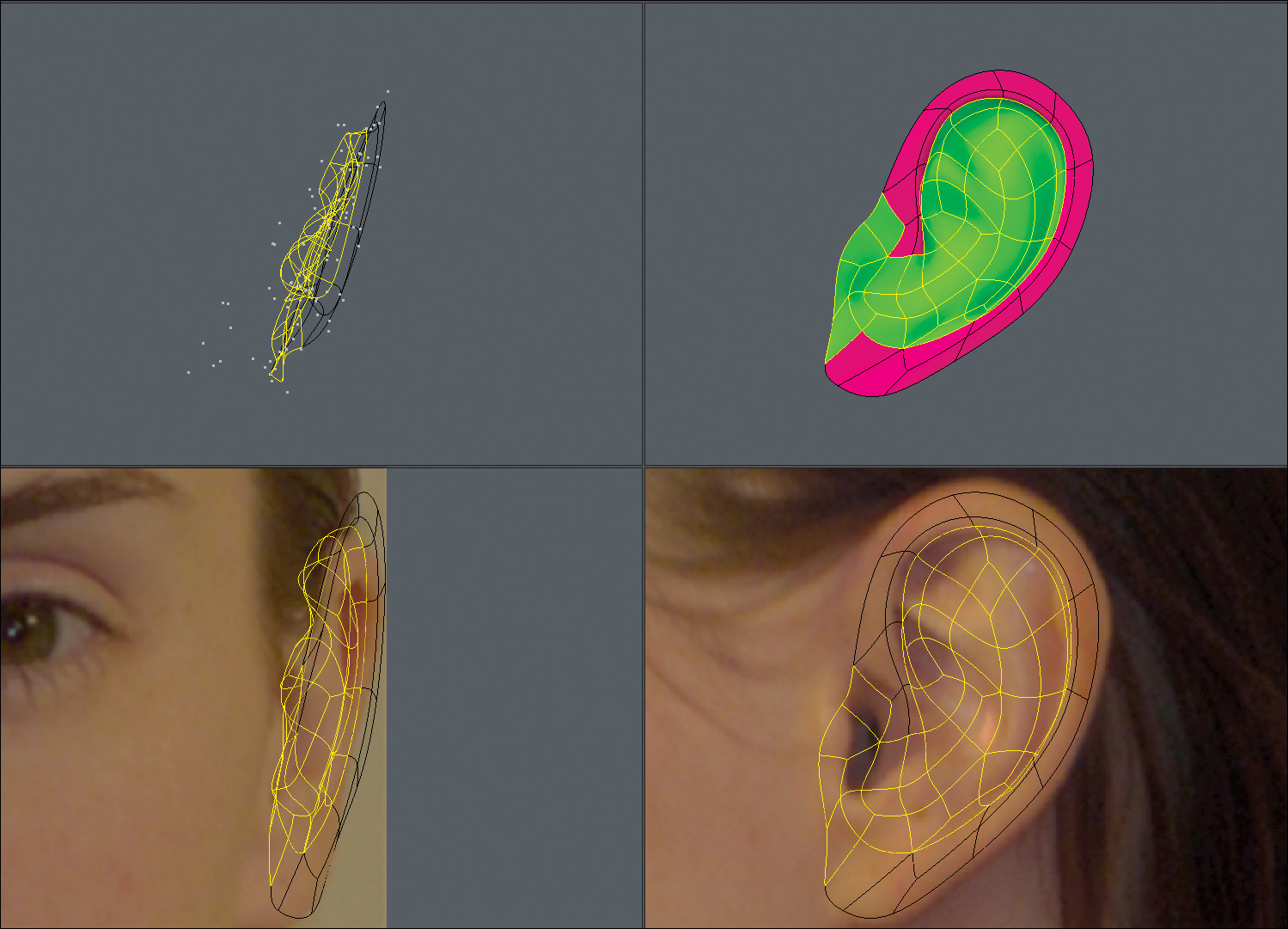
Next up was creating the external auditory canal. I selected the geometry shown in green in Figure 9.27, beveled it twice, and adjusted the mesh to create the canal.
[Figure 9.27] Depth in the auditory canal will add realism to your ear.

To finish off the ear, I extended the outer edges of the ear three times, wrapping the new geometry around to the back of the ear. Extending the edges off the ear and connecting them to the face mask allowed me to create a seamless integration of the components, as shown in Figure 9.28.
[Figure 9.28] Creating the back side of the ear is a snap by simply extending the outer rim of the ear. With the ear completed and connected to the rest of the face, the most detailed regions of the head are now complete.
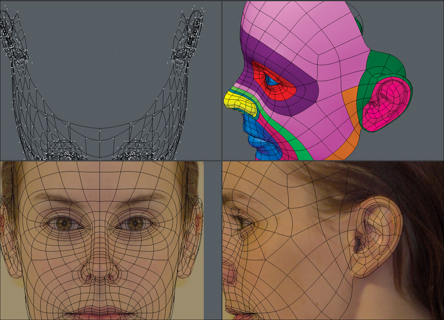
Finishing Off the Head
With the eyes, nose, mouth, and ears completed, I had light work ahead of me. Starting with the open edges on the forehead, I extended 11 times, connecting the newly created geometry to its bordering polygons with each extension until I reached the base of the neck. The result is shown in Figure 9.29.
[Figure 9.29] Keep the poly-count low for the back of the head because there is little to no detail needed.

I continued the process off of the jawline to create the throat area and finish off the neck (Figure 9.30).
[Figure 9.30] Give yourself enough segments in the throat area to allow for subtle deformations when a character is talking or swallowing.

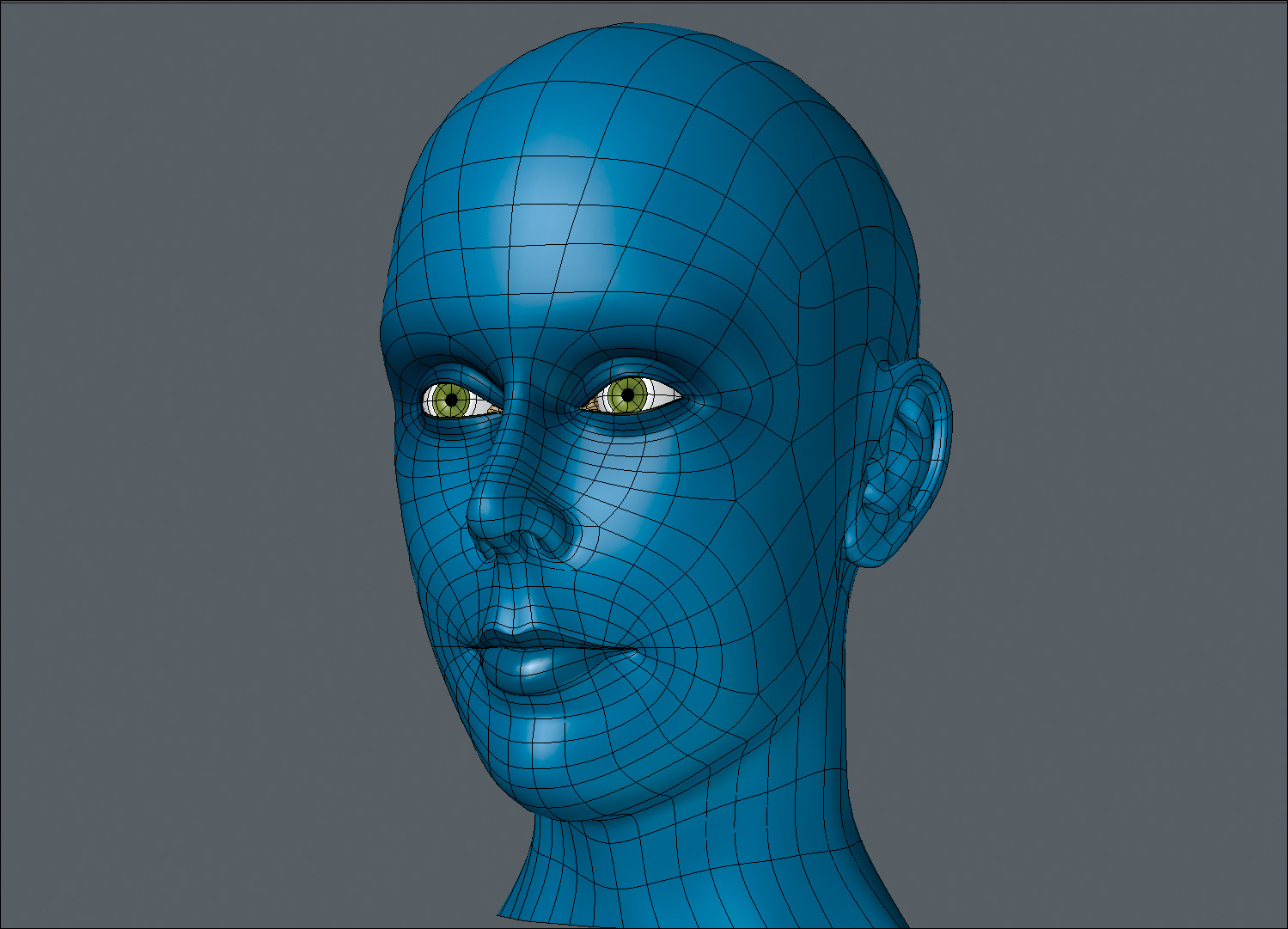
With all of the head’s geometry in place, I went ahead and resurfaced the mesh to get a better look at what I had created. The final result is shown in Figure 9.31.
[Figure 9.31] In short order I’ve created an all-quad mesh with clean poly flow that will hold up during facial animation.
Using this edge extend method of modeling a head, you’ll spend only 10 percent of your time creating new geometry and 90 percent pushing and pulling points into their proper place. This technique is quite straightforward and allows you to move quickly. Getting proper flow in your geometry is as simple as placing the polygons where you want them, and at its core, that is what makes this technique so favorable to modeling from background images.