Chapter Ten. Modeling a Stylized Character

Whether I’m working from another artist’s concept or pulling from my own imagination, I love building 3D characters. Without a doubt, digital character modeling is what attracted me to the animation industry, and it’s what has kept me satisfied as an artist, creatively and professionally, to this day. I’ve literally created hundreds of 3D character models, ranging from realistic to cartoon, but I have a passion for creating stylized characters. I like the idea of creating something that the world has never seen before—something that nobody could simply take a picture of.
Although it’s good practice to have clean geometry in every mesh that you create, it’s extremely important when building a character model. Creating a digital character model is one thing; creating a character that is easy to rig, texture, and animate, and renders properly is a different matter altogether. Every aspect of your model needs to have good topology with a manageable poly-count to make your mesh production ready. Simply put, character models need to consist of squeaky-clean geometry.

© Disney/Pixar
In this chapter, I show you one of the techniques I use to quickly create a complete, stylized, biped character model. I take you through the process of building clean geometry and show you how to find the form and detail of a character, starting from a simple box primitive. Although I demonstrate this technique on a cartoon-style character, it can be applied to any number of styles, including realistic. This technique is also not limited to character modeling, so feel free to explore the possibilities once you have an understanding of this method.
Box Modeling a Character Mesh
Box modeling is my favorite modeling method, and I find that it’s my go-to solution when building characters. Most times, I can box model a character faster than creating a 2D drawing of the same subject, making this method ideal not only for quickly developing character concepts, but also for producing finished meshes ready for production.
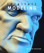
When I worked on Pixar’s animated short Partly Cloudy, I used the box modeling method to create an array of cute animals and props in a variety of shapes and details. Figure 10.1 shows a few of the characters you might recognize from the film.
[Figure 10.1] Working from a 2D artist’s concepts, I box modeled these characters for Pixar’s Partly Cloudy.
All images ©Disney/Pixar
When employing the box modeling technique, I find that I only use a handful of tools. Doing this allows me to focus on the creative aspects of modeling more than the technical aspects, while still delivering a clean mesh ready for production. For this modeling example, I didn’t work with reference material; instead, I chose to build a biped male character from my imagination while keeping the following goals in mind:
• Create an all-quad mesh with localized detail.
• Use subdivision surfaces.
• Build a clean mesh with good topology that is ideal for animation.
• Make extensive use of the box modeling method.
Getting Started
When starting a character model without reference, I prefer to start with the head. I find that the head drives the overall design of a character, and once I capture the look I’m after, the rest of the mesh can be child’s play. I also like to take advantage of symmetry on my character models, because it means I only have to model half the character and the software handles the other side.
Although you can start with any primitive as a base mesh when box modeling, I usually use a box. It’s extremely low poly and gives me an all-quad mesh to start with. To start the head, I created a simple box primitive and subdivided it to gain access to more polygons and to round off the base shape (Figure 10.2). Don’t make the same mistake many modelers do and subdivide the mesh multiple times at this early stage. Keep the mesh as light as possible for as long as possible. The lighter the mesh, the easier it is to define the shape and make broad changes throughout your model. I like to dictate where every polygon is being created, and subdividing the mesh multiple times would produce unnecessary geometry in many areas.
[Figure 10.2] Subdividing a box gives a rounder shape and a few more polygons to work with to construct the head mesh.

With that said, I did need more geometry to define the shape of this character’s head. I started by extending two of the quads on the lower portion of the base mesh to create the mouth and chin area. With this simple step, I could already see a basic head shape taking form. Figure 10.3 shows the results of the new geometry created.
[Figure 10.3] Extending two polygons from the bottom of the base mesh created the mouth and chin area of the head (left to right).

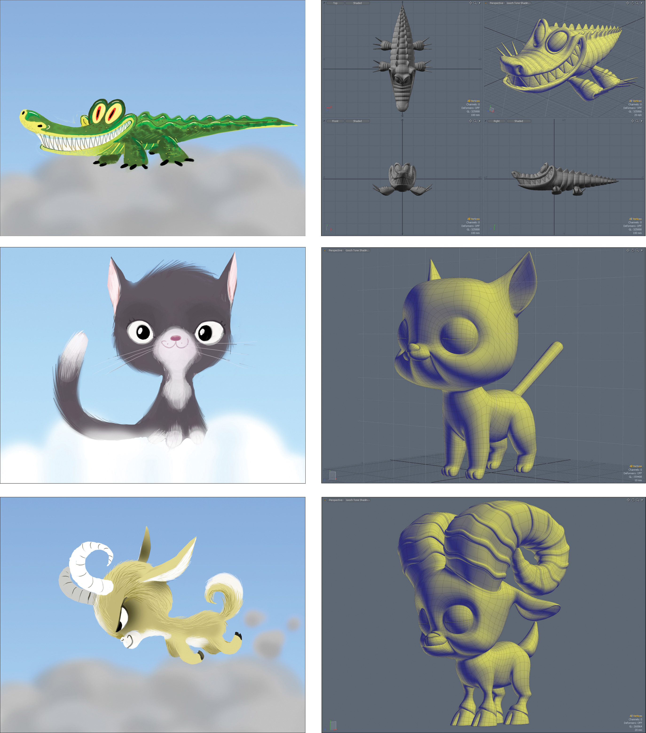
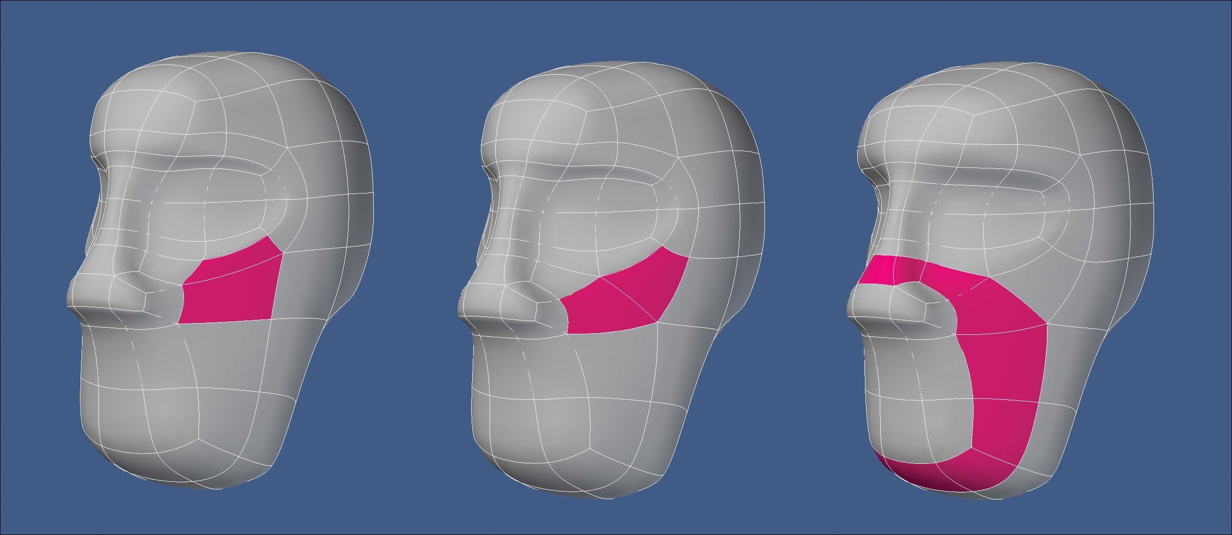
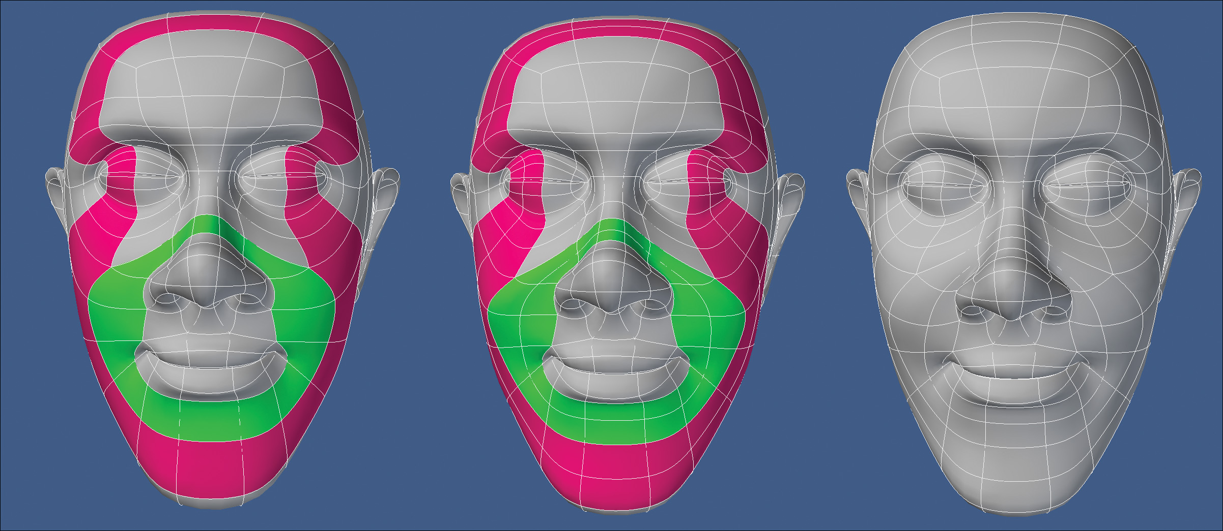
I still needed more geometry to work with, so I added a segment through the mouth area and edge beveled the segment that ran through where I envisioned adding the eyes. I added another segment through the newly created eye row of polygons that would act as a center line for where the eyes would be placed. I then edge beveled the segment running down the center of the head to produce a new row of polygons that could act as the bridge of the nose, give me more geometry for the mouth, and help shape the forehead and the back of the head. Figure 10.4 shows the results of these steps.
[Figure 10.4] I started laying the framework for the face by adding new segments to the base mesh. I cut through the areas in pink and edge beveled the segments to generate the areas in green (left to right).
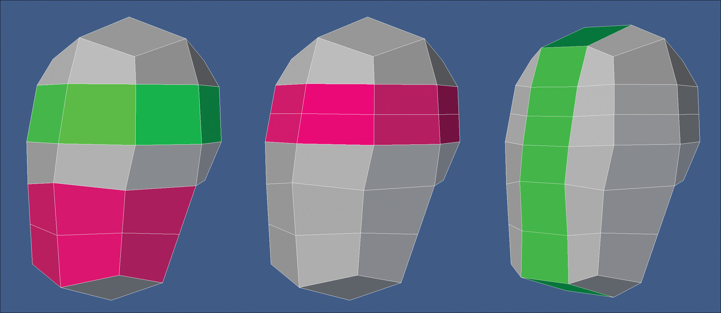
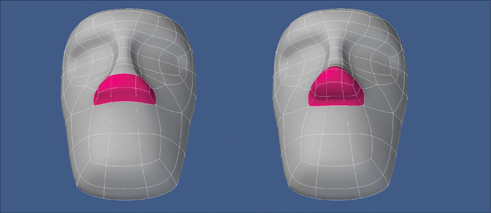
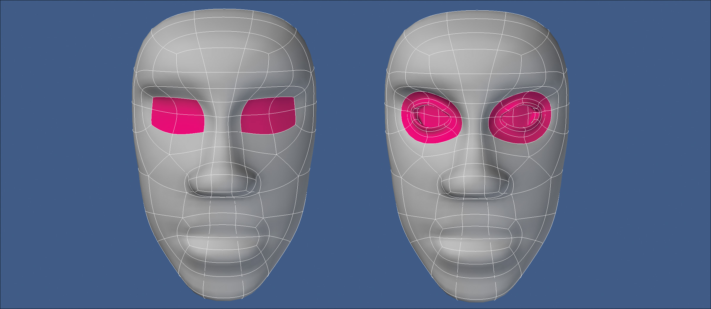
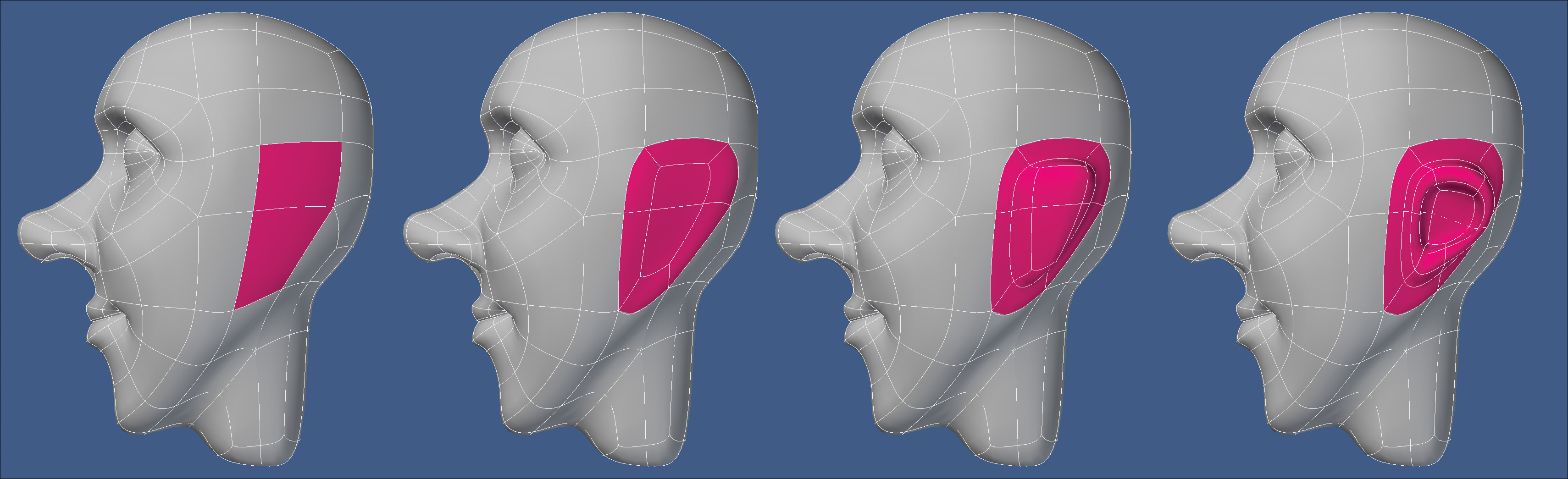
At this point, I wanted to keep any new polygon creation localized and not add any unneeded geometry to the back of the head. I turned my focus to the eye area and added a new segment running through the border of the face. I reshaped the eye area and then defined that region of the face by extending the geometry twice. This gave me the area I like to call the eye mask. Figure 10.5 shows this process.
[Figure 10.5] To create the eye-mask area of the face, I added a new segment that borders the face and extended the eye-mask region twice (left to right).

I avoided adding any more detail to the eyes and moved on to the nose. I used a technique that I developed years ago that is the quickest way I know to create the base nose shape. I simply selected an upside-down T configuration in the polys and extended them to produce the entire nose structure in one step. Unlike the other areas of the nose, I wanted the top portion (the root) to flow smoothly into the forehead. To do this, I reconfigured the geometry by spinning one edge on each side of the forehead and then tweaked points. Every 3D application has at least one tool that can perform this action, but each may call it something different. Some common names are SpinQuads, Flip Edge, Spin Edge, and Rotate Edge. Figure 10.6 shows these four steps.
[Figure 10.6] The entire base shape of the nose was produced by simply extruding the shape out of the base mesh and spending a few seconds tweaking the newly created geometry (left to right).
It’s never too early to have topology in mind when creating a mesh, so the next area I concentrated on was the character’s laugh line. A lot of artists forget to include a row of polygons that borders the mouth and nose, and also crosses over the bridge of the nose. This geometry mimics the underlying muscles in the face, allowing for clean deformations when the character speaks and makes expressions. All that was required for me to create this necessary feature was to spin one edge to redirect the polygon flow, thus producing a clean edge loop (Figure 10.7).
[Figure 10.7] Reconfiguring the polygon flow to produce a clean edge loop for the laugh line was as simple as spinning one edge (left to right).
Hopefully, you are starting to see the power of spinning edges to rapidly produce clean polygon flow. It truly is my secret weapon when box modeling, and once you’ve mastered the process, you’ll gain full control over the topology of your mesh.
I wanted to flesh out the character’s face more, so I extended the base of the nose to give it more shape (Figure 10.8).
[Figure 10.8] Extending the nose geometry allowed for a rounder shape (left to right).
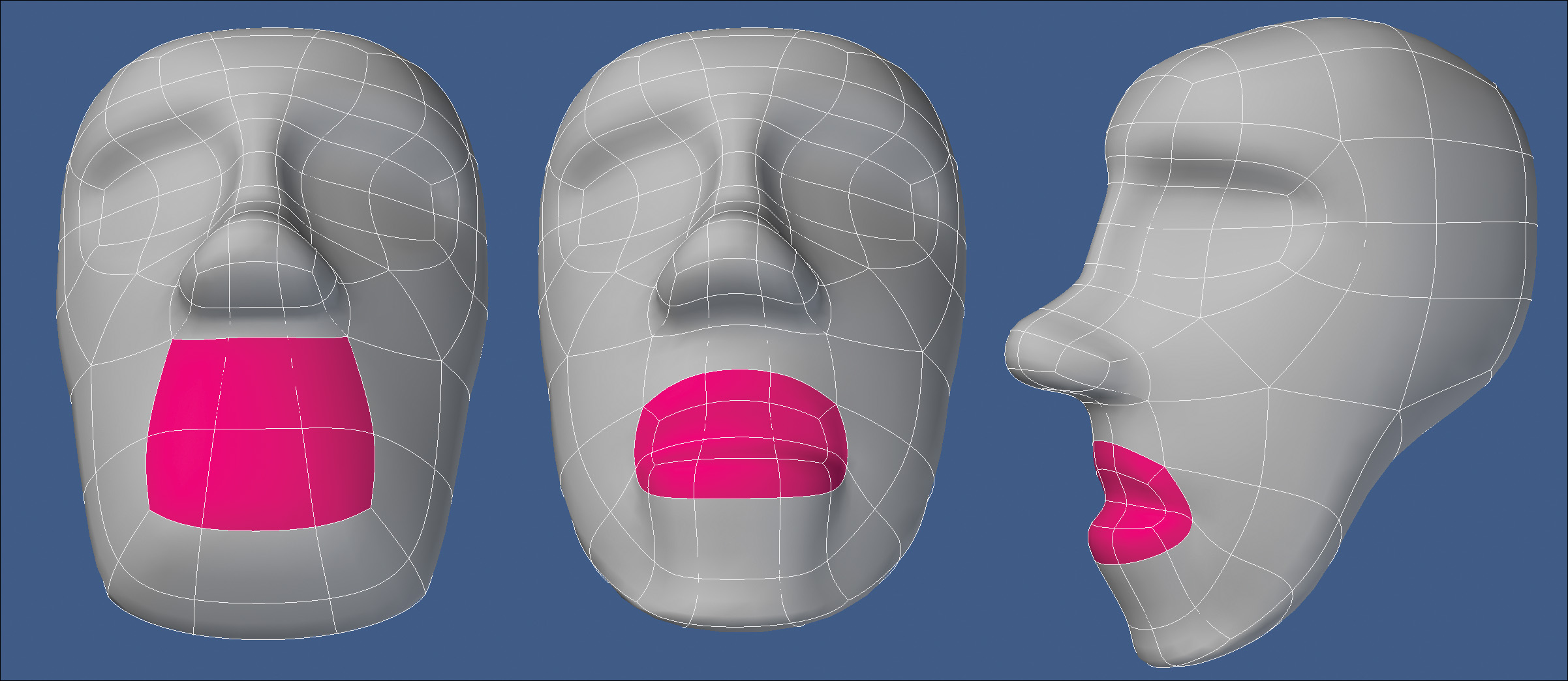
The template for the face was almost complete. The only thing left to create was the mouth. I selected the six polygons located just inside the laugh line, extended them, and tweaked the points to produce a rough mouth shape. Figure 10.9 shows the process.
[Figure 10.9] The rough shape of the mouth was created by extending and tweaking the geometry (left to right).
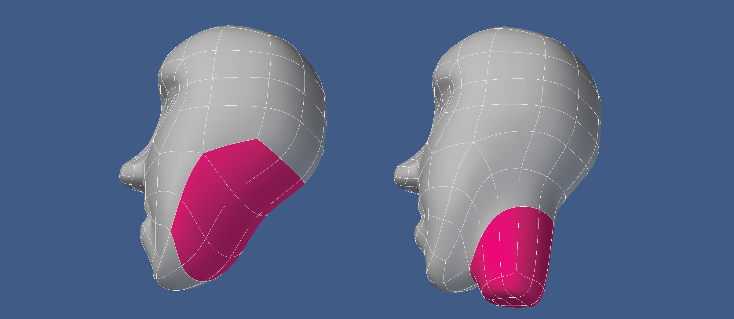
With all the facial elements prepped to be detailed, I added a neck by extending a group of polygons on the bottom of the head twice and reshaping them (Figure 10.10).
[Figure 10.10] Adding the neck allowed me to get a better idea of what I was going to do with the character’s jawline (left to right).
Detailing the Face
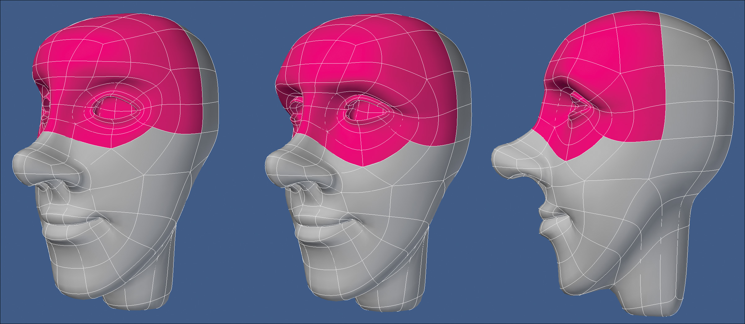
Next, I refocused my attention on the character’s eyes and extended the eye socket geometry a few times to form basic eyelids (Figure 10.11). I wasn’t concerned with how many segments were needed. I was more interested in the size and shape of the eyes.
[Figure 10.11] Extending the geometry that made up the eye sockets a few times allowed me to form the character’s eyelids (left to right).
With the basic shape of the eyes in place, I decided to finish off the nose. I extended the nostrils, added an additional segment through the nose, and reconfigured the geometry to get the shape I was after. Figure 10.12 shows the result. As with every area I detailed, I kept any addition to poly-count localized to that area. Doing so keeps the mesh light while still gaining needed polygons to get the shapes you’re looking for.
[Figure 10.12] Additional geometry needed for the nose was added locally instead of throughout the entire mesh (left to right).

Creating the mouth involved the same process used on the eyes. I simply extended the mouth geometry a few times and adjusted the points until I was satisfied with the shape of the lips (Figure 10.13).
[Figure 10.13] The mouth was created using the same process that produced the eyes (left to right).

With the eyes, nose, and mouth looking good, I spent a couple of minutes reshaping the brow and forehead. No new geometry was created at this time—I was simply pushing points around to define the shape I was after. I find that I spend 90 percent of my time pushing points and only 10 percent creating new points to push. It’s important to adjust the geometry as you build. This adjustment allows you to make changes more quickly, defining the character as you build instead of at the end of the modeling process. Figure 10.14 shows the transformation of the forehead and brow area.
[Figure 10.14] Tweaking the points’ placements on the brow and forehead gave me the shape I was after and made for a more interesting look for the character (left to right).
Before moving on to the ear, I wanted to do a little house cleaning on the side of the face. I knew it would be easier to tackle before the ear was in place, so I started by changing the polygon flow with a single spin edge. This created undesirable topology where the base of the ear would sit, so I chased the configuration past the ear area and to the back of the head. Chasing refers to spinning edges to move a particular polygon configuration from one area to another. You don’t remove the layout, you simply give it a new home. Figure 10.15 shows this process.
[Figure 10.15] Reconfiguring the side of the head’s topology produces much cleaner polygon flow and creates a nice edge loop from the chin to the top of the head (left to right).

While I was in cleanup mode, I reconfigured the neck geometry to produce cleaner topology. This required spinning a few edges (Figure 10.16).
[Figure 10.16] Spinning a few of the edges in the neck produced a cleaner mesh with better topology (left to right).
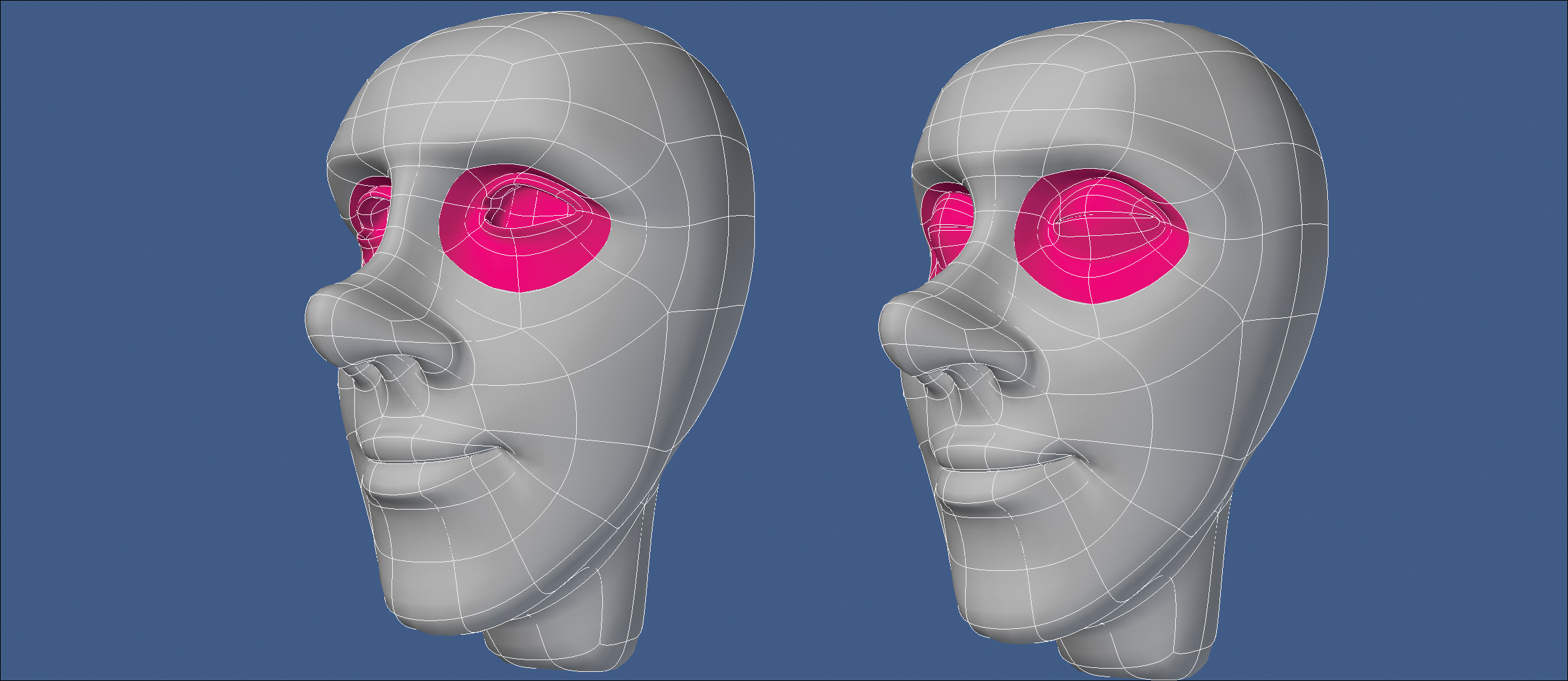
At this point I realized that I had forgotten an important detail on the eye geometry. Although I liked the shape of the eyes, I didn’t create enough segments to produce clean deformations when animated. One of the easiest ways to check for this is to model the eyelids closed. The last thing you want to do is deliver a mesh missing key segments to the rigging department that limits its ability to make your model shine during animation. That’s a situation where everyone loses, and it’s easily avoidable. Figure 10.17 shows the newly created segments and the character with his eyelids closed.
[Figure 10.17] Adding two new segments around the eyes allows for clean deformations when the eyes are opened and closed (left to right).
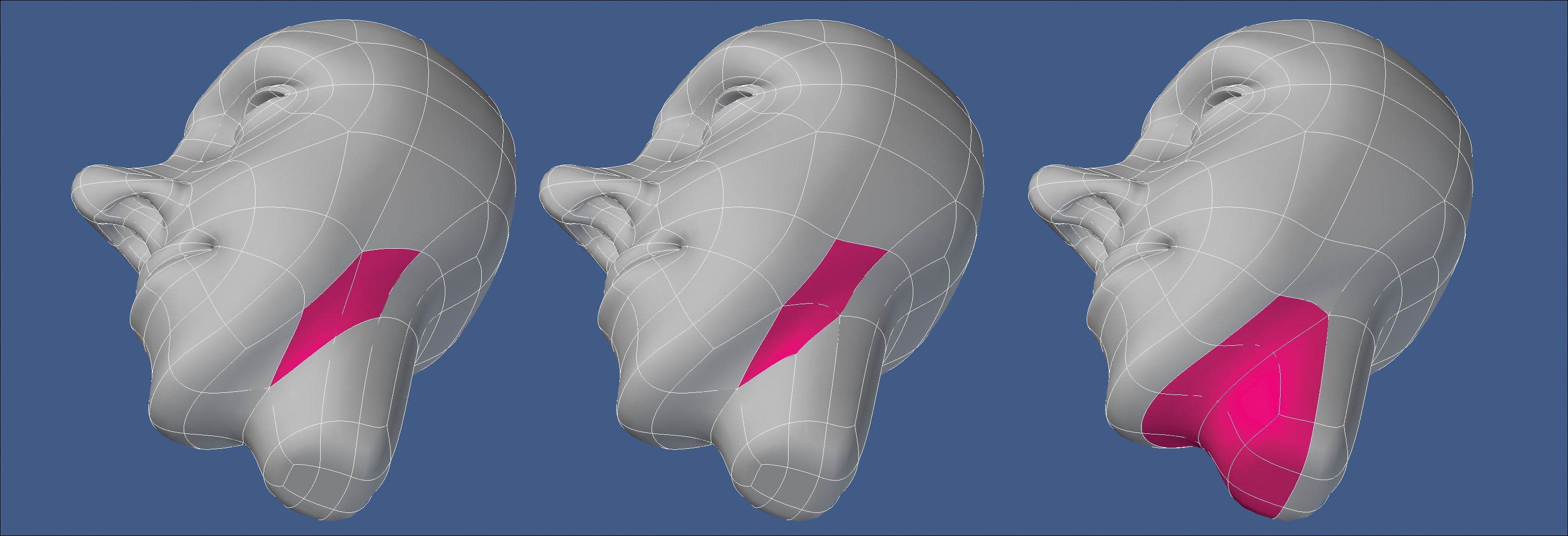
When it comes to box modeling, one of my favorite areas of a character’s head is the ear. I have a prime spot picked out for where I want the ear to be. I want the top of the ear to be in line with the corner of the eye and the bottom to line up just under the character’s nose. I only need two polygons to create an ear that can have any level of detail, from cartoon to realistic, but this character looked like he needed a stylized ear to go with the rest of his cartoony features.
I started off the ear by extending the two polygons a few times to create the basic shape and to give me more geometry to work with. You can see this process in Figure 10.18.
[Figure 10.18] Extending the two polygons a few times creates the basic shape of the ear (left to right).
I wanted a more defined shape to the ear, so I extended a patch of polygons at the top of the ear and spent some time reconfiguring the geometry by spinning edges and pushing points until I was happy with the results. Figure 10.19 shows the progression of the ear being refined.
[Figure 10.19] Extending the patch of polygons at the top of the ear allowed for the refining of the shape of the ear (left to right).

I thought the design of the ear was fitting for the character, but I wanted to give you an idea of how the same two polygons could produce a more detailed ear using the same process I just covered. Figure 10.20 shows the result of a few more minutes of extending, spinning edges, and pushing points.
[Figure 10.20] Any level of detail can be added to the ear by extending patches of geometry, spinning edges, and pushing points.

With the ear polished (and a backup ear with more detail saved), I wanted to add a few more segments to the head and neck before moving on to the body. I started by adding a segment to the neck and refining the shape. I thought it was too thick for the character design, so I made the circumference smaller (Figure 10.21).
[Figure 10.21] Adding a new segment through the neck allowed me to create a skinnier neck that was more fitting for this character design.

I finished off the head by adding two new segments to the face. The first segment was added to the chin, cheeks, eyelids, and forehead through one edge loop. I wanted to give myself more control points to work with when deforming the character for facial expressions during animation.
The second segment was added to the laugh line to ensure that I had the rule of three in place. The basic idea of the rule of three is to have a hold segment on either side of the segment through which the deformation will take place. In the case of the laugh line, the center segment creates the crease in the face, whereas the outer segments hold the cheeks and mouth in place. Figure 10.22 shows the new segments that were added to the face.
[Figure 10.22] Two new segments added to the face allow for more control points to aid in facial deformations during animation (left to right).
Building the Body
This character was in need of a tall, lanky body to match his thin goofy face. I selected the polygons that made up the base of the neck and extended them several times to give myself enough segments to shape the body. Once I roughed out the shape of the chest, midsection, and pelvic area, I selected the polygons that made up the shoulder and hips, merged them into n-gons, and converted them to polygonal mode (non-SubDs). Figure 10.23 shows the result of this process.
[Figure 10.23] Creating the body out of the neck is a quick task. It’s important to use the time you save to tweak the newly created geometry to get the shape of the body right before moving on to the next step (left to right).

Converting the shoulder and hip geometry to polygonal n-gons allows me to focus on the shape of the torso. This conversion also ensures that the point placement of the hips and shoulders are evenly distributed into a circular shape before creating the arms and legs.
The next step was to create the arms. I extended the n-gon at the shoulder several times, refining the shape with each extension. I made it a point to add the rule of three at the shoulder and elbow to ensure that proper deformations would occur during animation. Figure 10.24 shows the results.
[Figure 10.24] When creating arms on a character, it’s important to include the rule of three for the shoulders and elbows to produce proper deformations during animation.

I used the same process to create the legs for the character, making sure that I added the rule of three at the hips and the knees. I also used my trusty underwear rule. The underwear rule is a good way to check to see if your character’s pelvic area will hold up during animation. Basically, if you can select polygons that are in the shape of a swimsuit or underwear, you’re probably in good shape. Make sure there is a gap of polygons separating each leg and that there is geometry that separates the hip from the belly. I’ve seen too many character models that don’t have this topology, and it usually ends in disaster when rigging and animating. Figure 10.25 shows the results of creating the leg geometry, as well as the underwear rule in action.
[Figure 10.25] Always remember the rule of three for the hips and knees, and check to see if you have proper flow for the pelvic area.

With all four limbs of the character created, I extended the feet out of the end of the legs and reshaped them to look like they were wearing socks. I made sure that I included the rule of three at the ankle and the base of the toes. Most artists remember to add the segments at the ankles but miss the hold segments for the toes, causing the foot to deform in an unrealistic way when animated. It’s important to put just as much care and thought into something as simple as a foot as you would the character’s face. Figure 10.26 shows the feet being created.
[Figure 10.26] The ankle and base of the toes require the rule of three for solid-looking deformations (left to right).

Give ’em a Hand
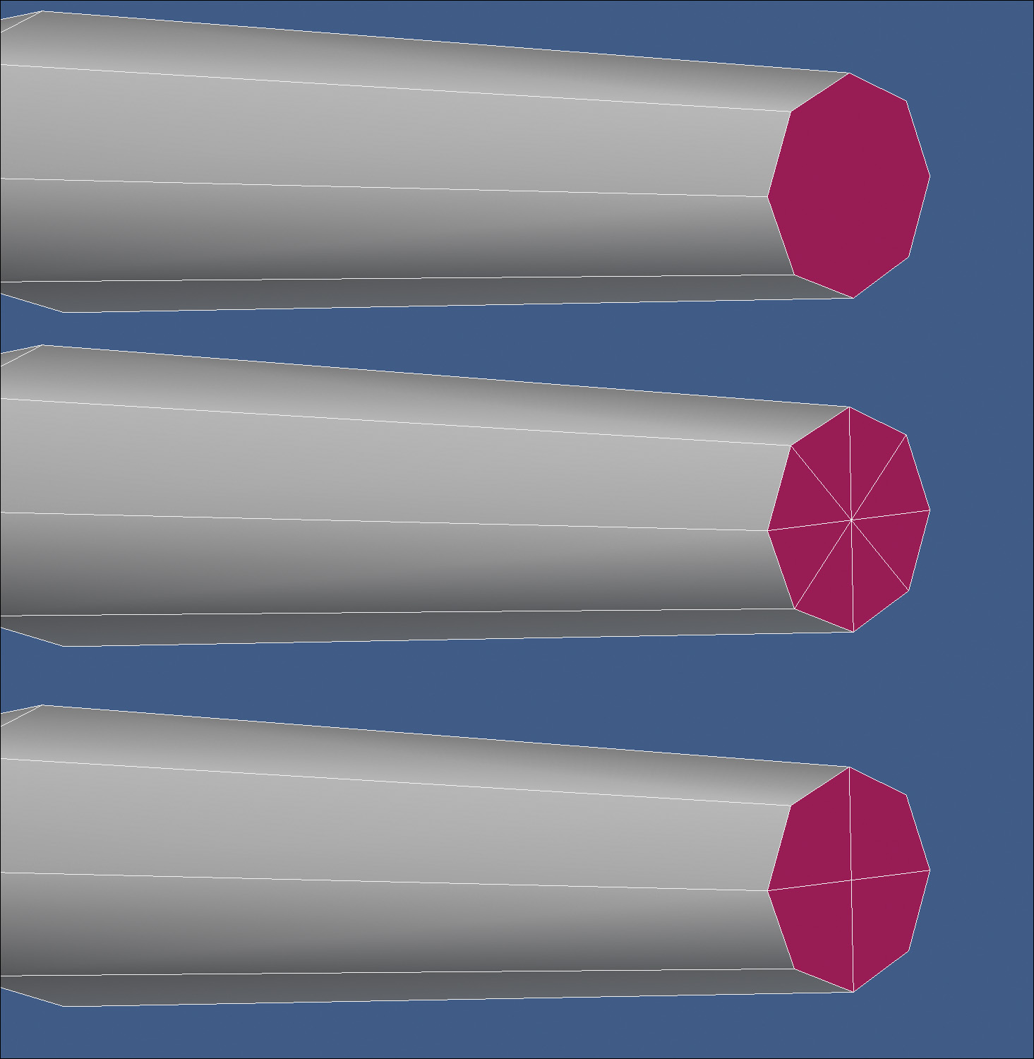
Before growing the hand out of the wrist, I needed to convert the n-gons that I created earlier back into four-point polygons. Having n-gons on a mesh that will deform during animation is a disaster waiting to happen. N-gons, like triangles, tend to produce pinching and render errors on the surface of the mesh when manipulated during animation. You should always strive for your mesh to consist of all-quad polys if deformation will take place. Figure 10.27 shows the process of converting the n-gons into triangles and then merging them into four quad polys.
[Figure 10.27] Converting the n-gons to quads allows for the hand to be extended with the proper polygon configuration (top to bottom).
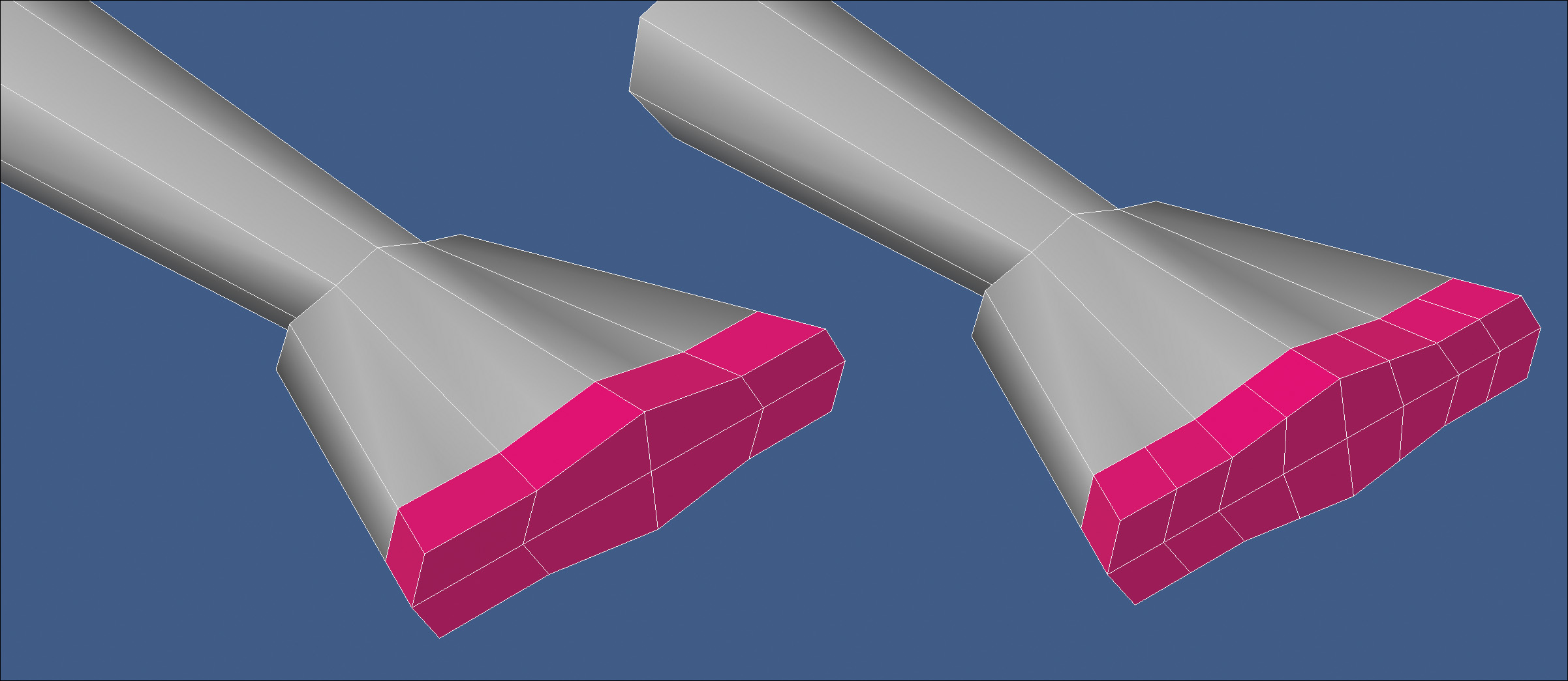
To create the base shape of the palm and top of the hand, I extended the wrist geometry once and then extended the sides of the palm out to add some width and enough geometry to create four fingers. Figure 10.28 shows these steps.
[Figure 10.28] Extending the wrist geometry allows for easy creation of the palm and top of the hand (top to bottom).

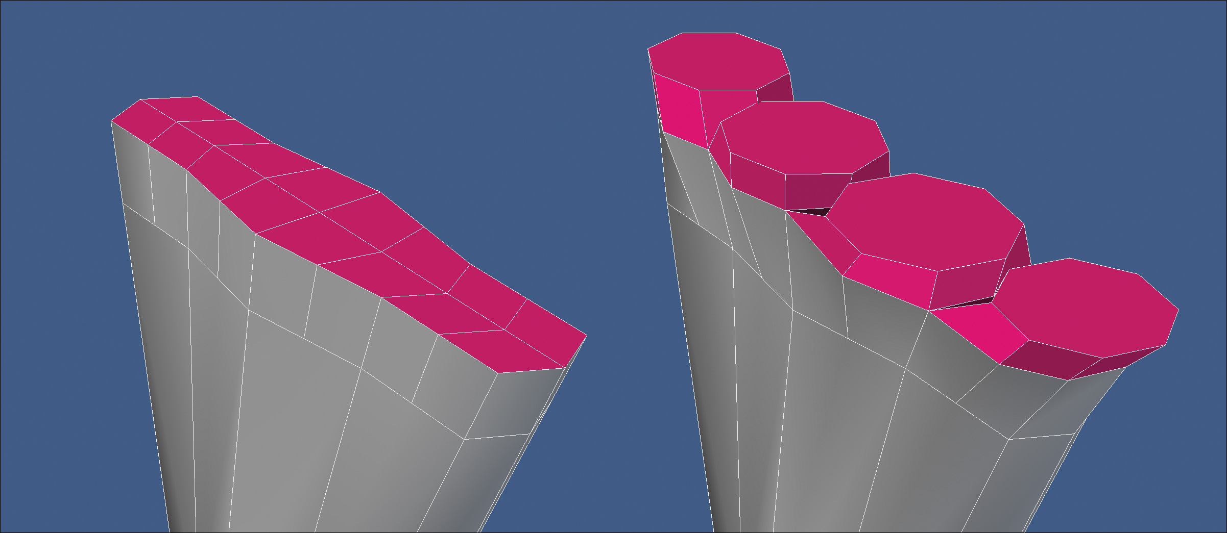
I needed more geometry to work with to produce the nice, round cartoon fingers I wanted for the character. To do this, I added segments to the ends of the hand. I created four n-gons on the top and four on the bottom of the hand. This was only a temporary measure that I would need to address at some point to get the model back to its all-quad topology. These new segments are shown in Figure 10.29.
[Figure 10.29] Adding additional segments allows for rounder fingers to be created from the hand (left to right).
Using the same technique that I used on the shoulders and hips, I created the base for the four fingers (Figure 10.30).
[Figure 10.30] Taking the time to reshape the base of the fingers makes light work of actually growing the fingers later (left to right).
Before adding the base of the thumb, I needed two more segments running through the hand, so I added them and reshaped the hand to make it less boxy. Figure 10.31 shows the results.
[Figure 10.31] Additional segments were added to the palm in preparation for the base of the thumb and to produce a less boxy hand shape (left to right).
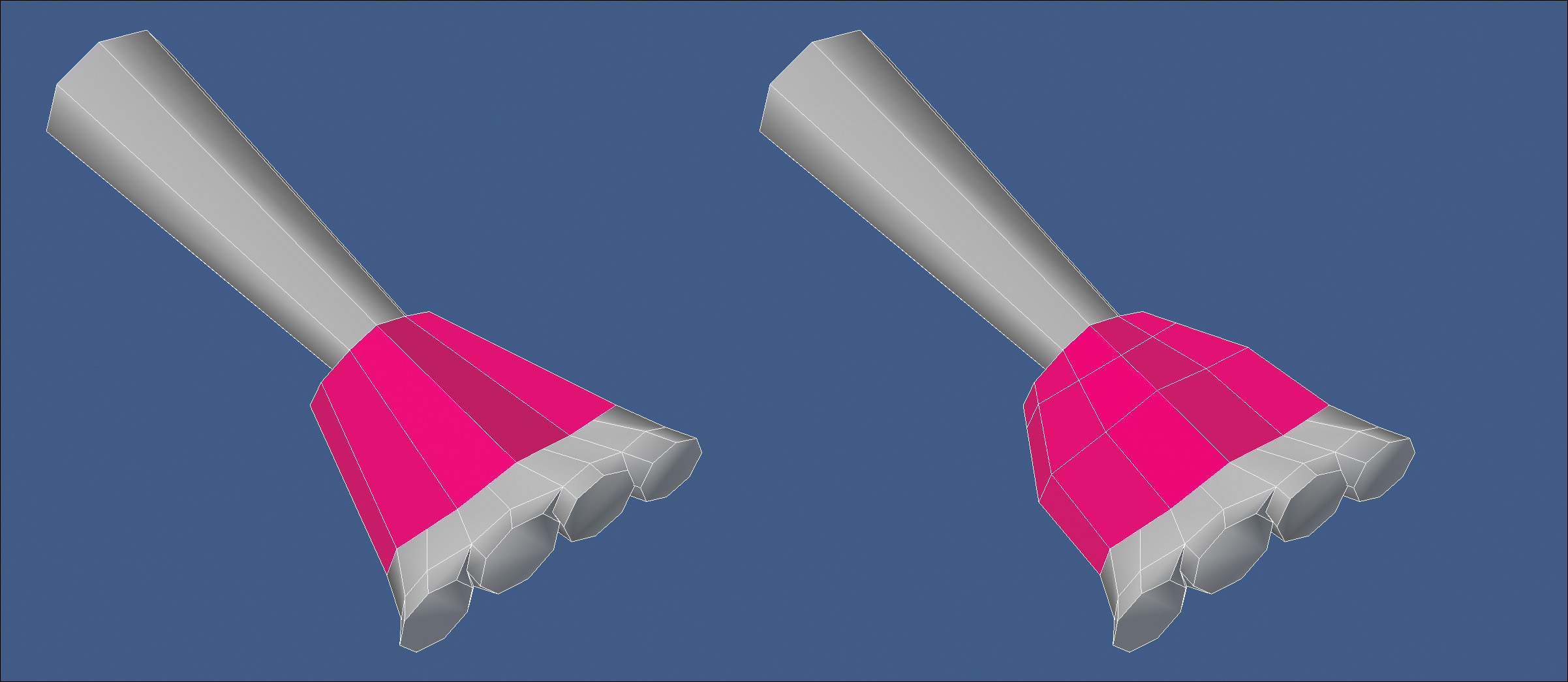
The base of the thumb was created, and the hand geometry was adjusted. My goal was to create what looked like a hand that had its fingers cut off. Figure 10.32 shows the resulting mesh.
[Figure 10.32] The base of the thumb was added to prepare for creating all five phalanges.

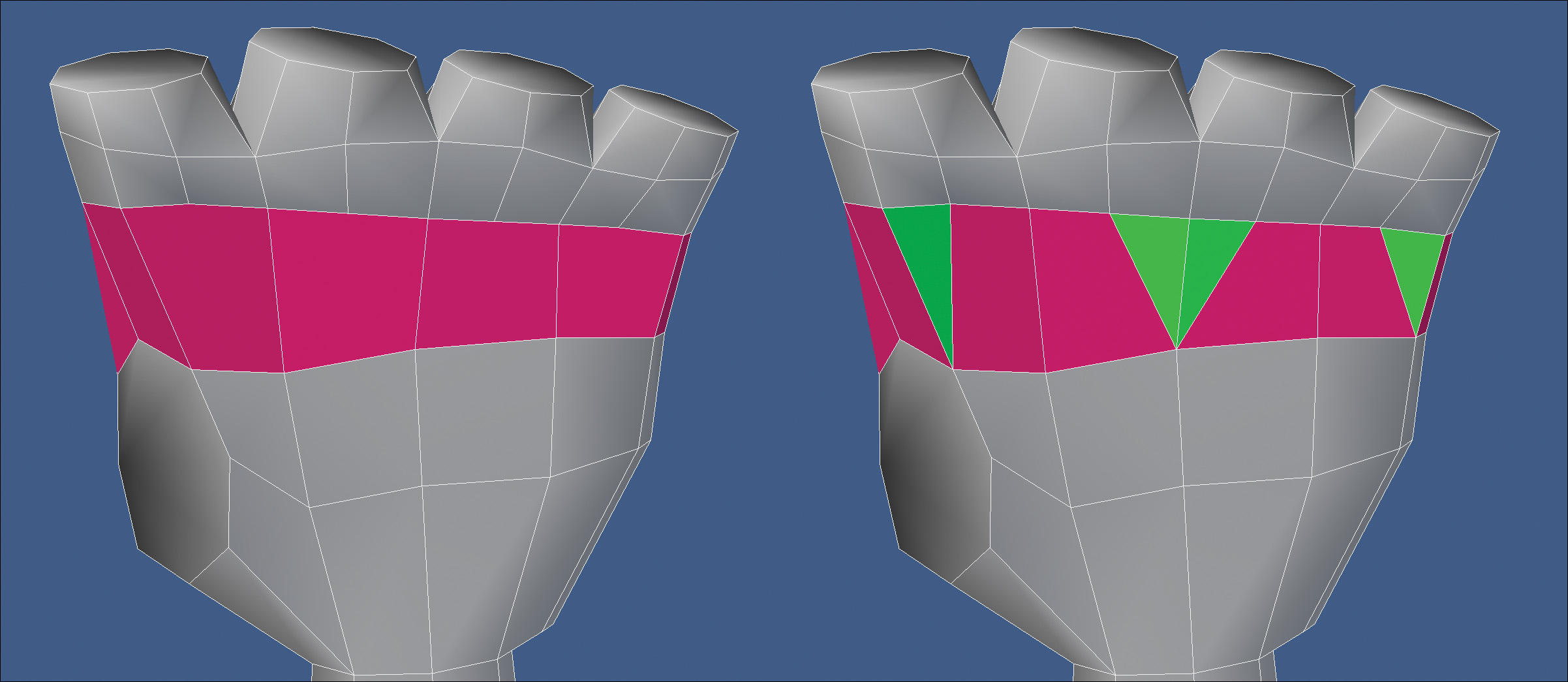
Before growing the fingers and thumb out of the hand, I wanted to clean up the n-gons I created earlier. I started by converting each n-gon into a quad and triangle combination on both the top and palm of the hand. Figure 10.33 shows the result of the conversion on the palm of the hand.
[Figure 10.33] To remove the n-gons created earlier, a quad-triangle combination was used (left to right).
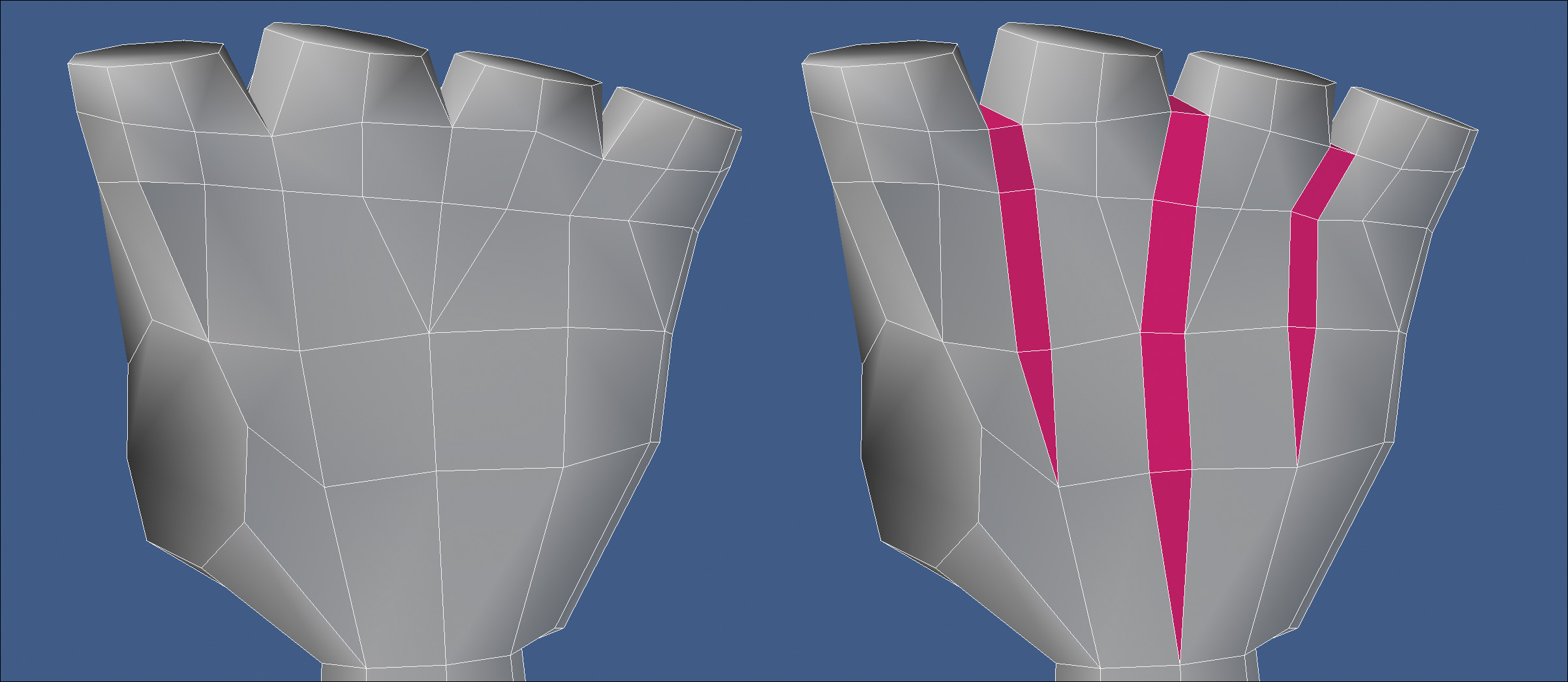
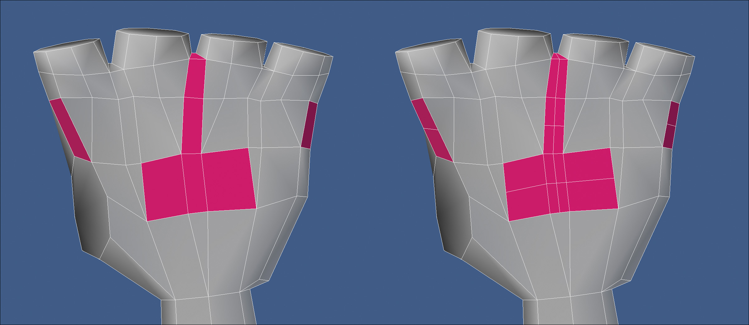
I also wanted to add a gap between each finger to allow them to deform better when spread open during animation. To do this, I created an edge bevel down the top and palm of the hand. Figure 10.34 shows the result of the edge bevels on the palm of the hand.
[Figure 10.34] Adding gaps between each finger allows the hand more flexibility when animated (left to right).
I prefer my meshes to be made up of all quads, because they deform better and transfer between different software packages much easier. At this point, the hand was unacceptable in this regard, so I created new edges that converted all of the triangles into quads. Figure 10.35 shows the conversion. The topology was far from ideal, but I planned to address the issues once I had the entire hand in place. At this point, I knew I was halfway there with the mesh being made up of all quads.
[Figure 10.35] Adding edges to the mesh allows for all of the triangles to be converted to quads (left to right).
I was ready to add fingers to the hand, so I started with the index finger. Because I prepped the base of the fingers early by making them round, all that was left to do was extend several times and convert the tip from an n-gon to quads, using the same technique I showed for the wrist earlier. I made sure to include the rule of three for each joint on the finger before moving on to the other fingers. Figure 10.36 shows the progression of all the fingers being created.
[Figure 10.36] Growing the fingers out of the hand was an easy task because I prepped the geometry at the base of the fingers earlier during the modeling process (left to right).

With all the geometry created for the hands, it was time for a bit of cleanup on the palm and top of the hand. The first issue that needed to be addressed was the shape. The thumb was a little too close to the index finger, and the palm was too short. Both issues were easy to address by simply moving the thumb towards the body of the character and pulling all four fingers away from the body. I also added a third segment to the wrist to apply the rule of three.
I then turned my focus on the topology of the mesh. Spinning several of the edges and pushing points, I reconfigured the geometry to create better polygon flow, thus allowing for better deformations when animated. Figure 10.37 shows where the hands started and what they looked like after they had been reconfigured. By using this topology, I was able to transition from 28 polygons on the edge loop located at the knuckles down to 8 polygons at the wrist. This should be a shining example of how you can add localized details on any model without adding unnecessary geometry elsewhere on the mesh.
[Figure 10.37] Taking the time to reconfigure the hand’s topology pays off when the character is rigged and animated. The original mesh is on the left, and the final topology of the hand is on the right.
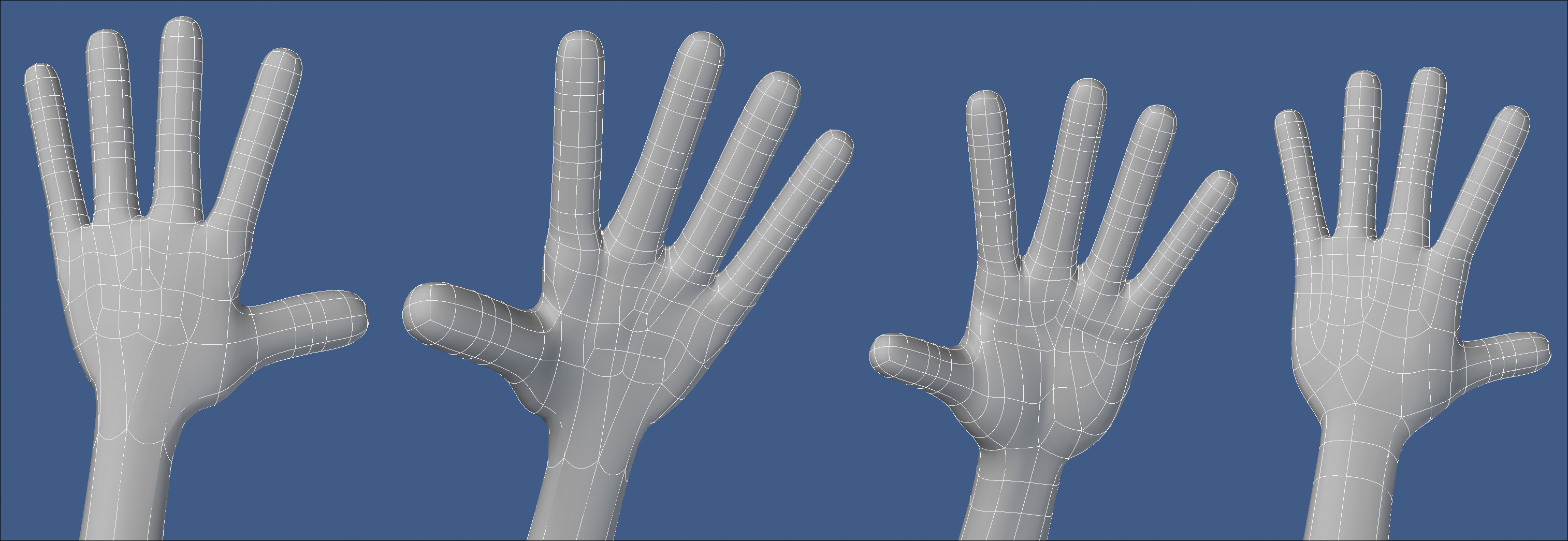
The great thing about modeling hands is that you have reference “handy” at all times. Be sure to create multiple shapes with your hands when referencing them to see how they deform in the various poses. This will give you an idea of where you should place edge loops for deformation.
Final Character Review
With the hands completed, I had a full character modeled, and took some time to review the mesh. I always like taking a break from the mesh at this point so that I can come back with a fresh set of eyes and look for anything I may have missed. Some particulars that I look for include:
• If I’m working from reference material, does the mesh match the reference?
• Did I include the rule of three in all the right areas?
• Is 100 percent of the mesh created out of four-point polygons?
• Does the mesh have proper polygon density?
• Is the mesh in the proper pose for rigging? (T-pose or relaxed pose)
• Is the mesh facing in the correct direction with its feet planted at zero on the Y axis?
• Is the mesh the proper scale?
• Does the overall mesh have clean topology?
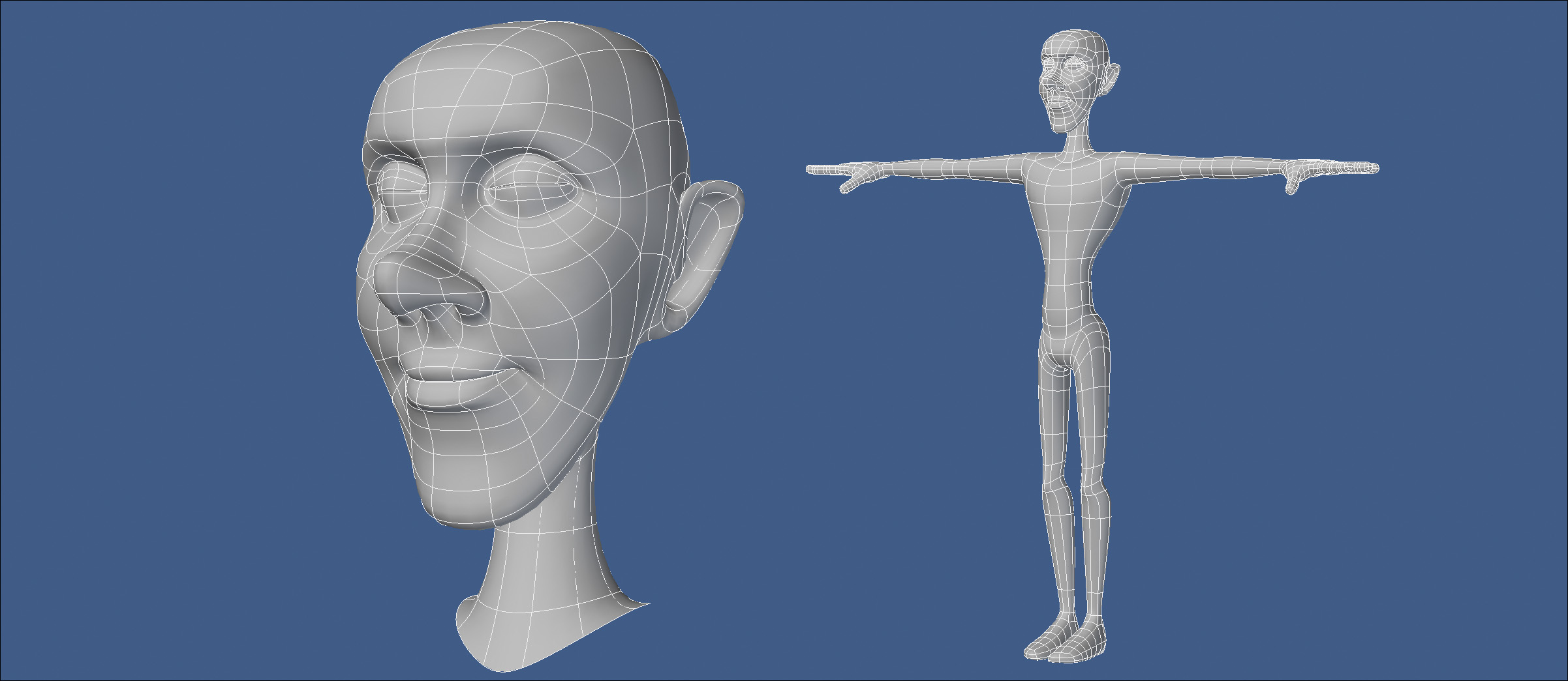
After my review of the mesh, I was satisfied with the look and structure that I had created. The model consisted of 2,200 quads. Half of those polygons were used on the hands, and less than a quarter on the head. You can check out the final mesh in Figure 10.38.
[Figure 10.38] The final mesh is ready for some clothes, hair, and other accessories to add to the character’s personality.
Depending on the production requirements, you may find that the base mesh needs to have a higher density. You can accomplish that by simply subdividing the geometry as many times as required to hit your target density. Figure 10.39 shows the character after being subdivided once. Be sure to save a version of the object before subdividing it so you can always go back and make broad changes quickly on the lower-resolution mesh.
[Figure 10.39] Subdividing the geometry creates a denser mesh, which is sometimes required for production.
