
Chapter Seven. Polygonal Modeling

This portion of the book represents the first of several chapters that are designed to sharpen your problem-solving and observational skills, as well as hone your digital modeling skills through real-world digital modeling examples. In this chapter, I walk you through the creation of 3D text and the digital modeling of a complex seam pattern into a mesh with a focus on polygonal modeling.
Modeling 3D Polygonal Text
A typical 3D text job is creating a logo. Logos, of course, are symbols or designs used by companies and individuals to help give them or their company an identity. Just about every company has one, and with millions of companies in the world, that means there is a pretty good chance that at some point in your career you’ll be tasked to create one in 3D.
3D logo creation is not just limited to entry-level spinning logos created by artists just getting started in the industry. Entire studios have been built and survive off the creation of 3D logos used for print, broadcast motion graphics, and more. The logo for Sister Act on Broadway (Figure 7.1) is an example of 3D being used for signage in New York City. Also, just about every summer blockbuster film opens with several studio logos that have been created in 3D.
[Figure 7.1] This Sister Act logo is a great example of how 3D has spread into new markets.

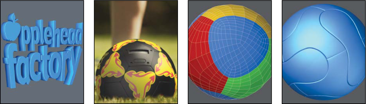
The techniques used to create professional 3D logo meshes can be a valuable skill set that carries over to other areas of digital modeling. In this section I explore the process of creating a 3D logo from an existing 2D design. I’ve selected the Applehead Factory logo (Figure 7.2) because it poses a few challenges that may come up on future models.
[Figure 7.2] Creating a 3D version of the Applehead Factory logo will be our goal for this section.

Vector and Raster Images
It’s common that a client will supply a logo as an EPS or Illustrator file (vector file), and most 3D software has the ability to load these formats.
Vector
Vector graphics use geometrical primitives—such as points, lines, curves, and shapes, which are all based on mathematical equations—to represent images in computer graphics. They are resolution independent, making them ideal for print graphics. The vector data is converted into editable geometry when imported into 3D software, which speeds up the 3D modeling process and can help ensure that the logo is technically accurate by working with a client’s file.
Raster
Just as often, a client will only supply you with a raster image. Raster files are made up of a rectangular grid of pixels, or points of color, stored in image files with varying formats. Their resolution is based on the number of pixels that make up the image, and when imported into 3D software for modeling, the image is used as a template to build on top of.
In the example in this section, I walk through the construction of a logo from scratch, using a small raster image, so that I can cover some useful techniques that would not be discussed if I used a vector file.
Getting Started
Before I start modeling, I like to study my reference (in this case the logo itself) and come up with a strategy for how I will move forward. For the Applehead Factory logo, the shapes were fairly simple letterforms, but they were not created from an existing font. This meant I would need to model each letterform from scratch. To make the logo 3D, I’d need to give it depth and add details that improved its quality.
I started by counting the number of shapes I needed. Although there are 3 symbols (the factory and two smoke plumes) and 16 letters, there are actually only 18 individual shapes that I needed to construct because the r and the y connect into one solid shape.
At first I thought I could cheat and reuse the p and the e shapes, but after close inspection, I discovered they are slightly different. It would have been tempting to take a shortcut and reuse the shapes, and although most people might not catch it, I can almost guarantee the client would. Shortcuts and cheats are a must in this industry, but make sure you’re choosing shortcuts that help you meet your end goal quicker, not those that change your end goal of producing a mesh that is 100 percent accurate to the supplied reference material.
I decided to use a mixture of point-by-point and primitive modeling methods to create these shapes, because I’ve found this technique to be the fastest way to create custom-shaped polygons. I had a pretty sound game plan, so it was time to get started. Without a game plan, I might have found myself having to back track halfway through the modeling sessions for lack of forethought.
Creating the 2D Base Mesh
I used the client-supplied reference image of the logo in the background as a template to work from. Because the 18 shapes are all independent, I could have started anywhere, but I wanted to get that factory shape out of the way first.
I created 16 points, placing one point at each corner of the shape. I made sure to zoom in as close as possible to ensure proper placement. Once I had the points created, I selected them and then converted that selection into a polygon. Figure 7.3 shows the result of this process.
[Figure 7.3] Each point needs to be accurately placed based on the reference image (left). This shape was created by the selected points being converted into a polygon (right).

That shape was the easiest of the bunch because it consisted of nothing but straight lines. Every other piece contained curved components that required far more points to produce the proper shapes. Placing each of these points by hand could have been time-consuming and produced undesirable results.
I have a few options available for creating shapes:
• Placing the points by hand: This technique is identical to how I approached the factory shape and requires the placement of each point by hand.
• Using primitives: These are basic geometric shapes that are the building blocks for many other shapes and forms, and using them to help create detailed curves is a technique that I’ve successfully applied for years. I usually use a disc primitive (a cylinder shape), and the idea is to create the disc with a portion of its edges conforming to the shape you are attempting to create.
Once I create the disc, I select and copy the points I need, and then remove (delete) the disc object. With the points I copied still stored in the system’s clipboard, I simply paste them back into the model (Figure 7.4). I can repeat these steps until I have all the points needed to make up the desired shape.
[Figure 7.4] The top portion of this disc primitive has been lined up to the edge of the apple shape (left). The selected points need to be copied to the clipboard before removing the disc (middle). Once the disc is removed, the copied points are pasted back into the object file (right).

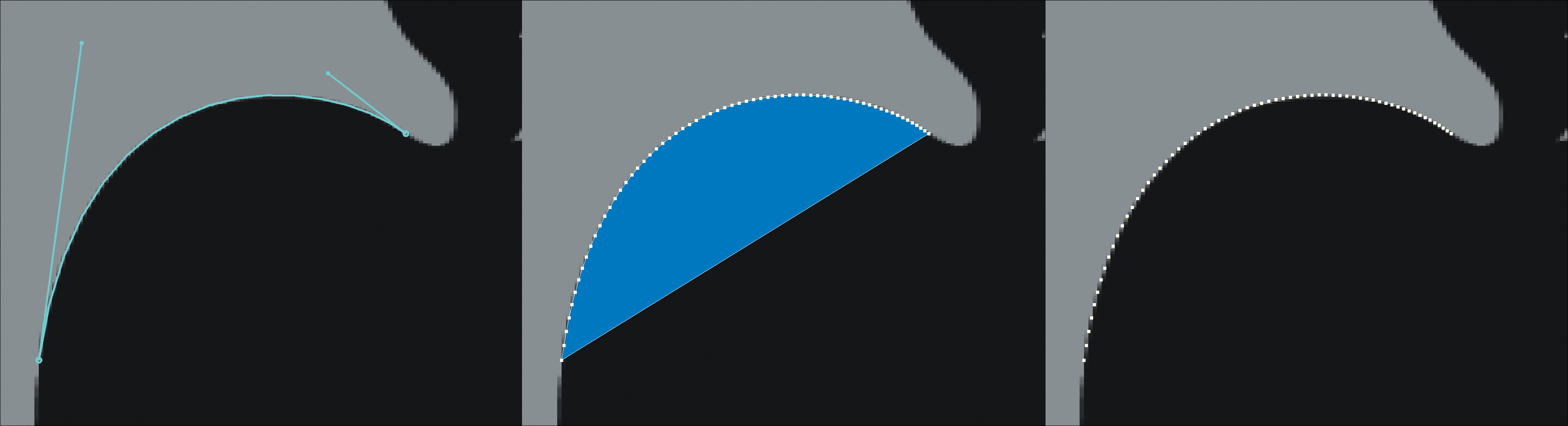
• Using splines: Splines (curves in 3D space) are probably the most common and preferred way of generating multiple points along a curve. Similar to the primitive method, I simply create a spline based on the shape I’m building. With the spline created, I convert it to a polygon and copy the points I need, paste the points back into the model, and repeat as needed. Figure 7.5 shows these steps.
[Figure 7.5] A Bézier spline is used to trace the outer edge of the apple shape (left). The spline is converted into a polygon, and the points are copied to the clipboard (middle). The result of pasting the points for the clipboard (right).
A good idea when working with splines is to create copies before converting them to polygons so that you can always return to the original source at a later time. I never like re-creating something I’ve already created; it is not an efficient use of my time.
I decided to use a combination of all three of the preceding options because the majority of the letterforms have a mixture of straight and curved shapes. At this point I didn’t worry about how I was going to get the apertures (holes in the letterforms) and simply created them as separate polygons.
As I finished the points for a shape, I selected them and converted the selection into a polygon (Figure 7.6).
[Figure 7.6] All of the necessary points for the apple shape have been created (left). This polygon was created from the selected points (right).

Once all the shapes were created (Figure 7.7), I focused on getting the apertures cut into the letterforms that need them. Booleans—modeling tools that let you add, subtract, and intersect one mesh with/from another—are pretty standard fare for this type of operation, so I decided to use them to tunnel the aperture shapes through the letterforms (Figure 7.8).
[Figure 7.7] The result of all the shapes being created, including the letterform’s apertures.

[Figure 7.8] The shapes that make up the holes are selected and used to create the apertures in the letterforms.

From 2D to 3D
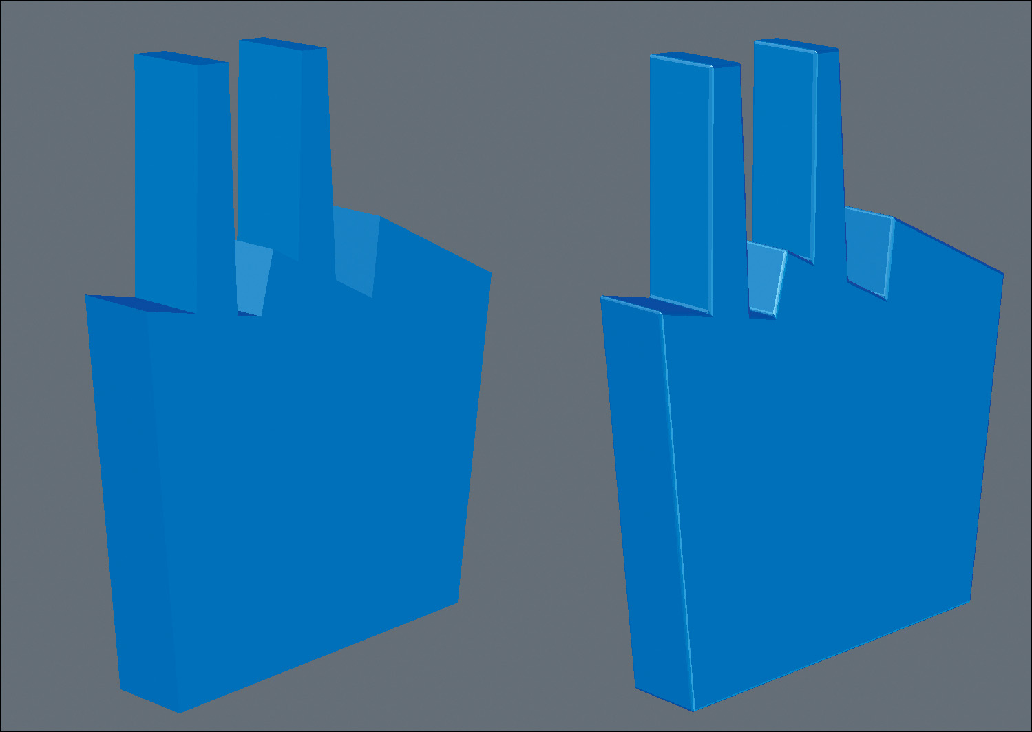
With the 2D base mesh complete, it was time to add some dimension to this logo. I’m not a big fan of the “Superman logo” effect of a massive amount of depth, so I went for a more subtle depth on this logo. I used the Extrude command to give thickness to the shapes (Figure 7.9).
[Figure 7.9] These figures show the before and after of extruding the base logo mesh.

You could call this logo final, if you were a hobbyist. Although I brought this 2D logo into 3D space, it was missing something that most artists overlook that could take their models to the next level: micro-bevels.
Micro-bevels, Chamfers, and Fillets
When most people hear about using micro-bevels on their objects, they immediately think it must be a special tool or plug-in. A micro-bevel is a small beveled edge connecting two surfaces. If the surfaces are at right angles, the micro-bevel will typically be at 45 degrees. Although the term micro-bevel is sometimes also used to describe both chamfers and fillets, they are actually quite different from each other:
• A chamfer is a beveled edge connecting two surfaces. Another way to describe it is as an angled cut applied to an exterior edge. In Figure 7.10, the edges on top of the object are chamfered to create a beveled edge.
[Figure 7.10] The outer edges of this shape are too sharp and need smoothing (left). The chamfer on these edges can help prevent it from looking too CG (right).

• A fillet is the rounding off, or beveling, of an interior corner. In Figure 7.11 the interior edges of the model are given a small bevel.
[Figure 7.11] The interior edges of this shape are also sharp and need refining (left). A fillet is applied, giving a much more realistic inner seam to this object (right).

You can see why chamfers and fillets fit in the micro-bevel category, but why use them? Look around you and try to find something, anything, that has a razor sharp edge. It’s harder than you think. It’s quite rare that an edge in the real world lacks some form of rounding. That means adding edge rounding can help you mimic the properties of real-world objects.
Another equally important reason for using micro-bevels is that they catch light on their surfaces and produce a highlight along the edges of the model. This can not only mimic real-world properties of an object, but can help define the shape in a render.
When you compare an object that has micro-bevels with one that doesn’t, it becomes quite obvious why you’d want to use them on your meshes (Figure 7.12). Professionals can spot them a mile away, and the lack of micro-bevels usually makes your work look more CG than realistic. It’s good practice to add micro-bevels to your modeling checklist and to include them whenever possible.
[Figure 7.12] The object on the left suffers from a very CG appearance. The object on the right has a much more realistic look to it thanks to micro-bevels.
For the Applehead Factory logo, I created these bevels on each letterform individually instead of beveling all of the shapes at once to ensure that they all produce clean results. It was important that I use the same bevel values to produce a consistent look. Figure 7.13 shows several of the shapes with micro-bevels created.
[Figure 7.13] The micro-bevels added to the edges of these letterforms will increase the quality of the final render by catching highlights along the beveled surfaces.

Clean Up
I chose the Applehead Factory logo for this example knowing it would create a common issue that I could use as an example. Bevels often produce errors in corners with sharp angles caused by overlapping polygons, which can produce render errors and unsightly geometry. Many 3D artists will tell you to avoid fonts that are prone to produce these errors when beveled, but that isn’t very useful if you are trying to re-create a specific shape based on a client’s logo.
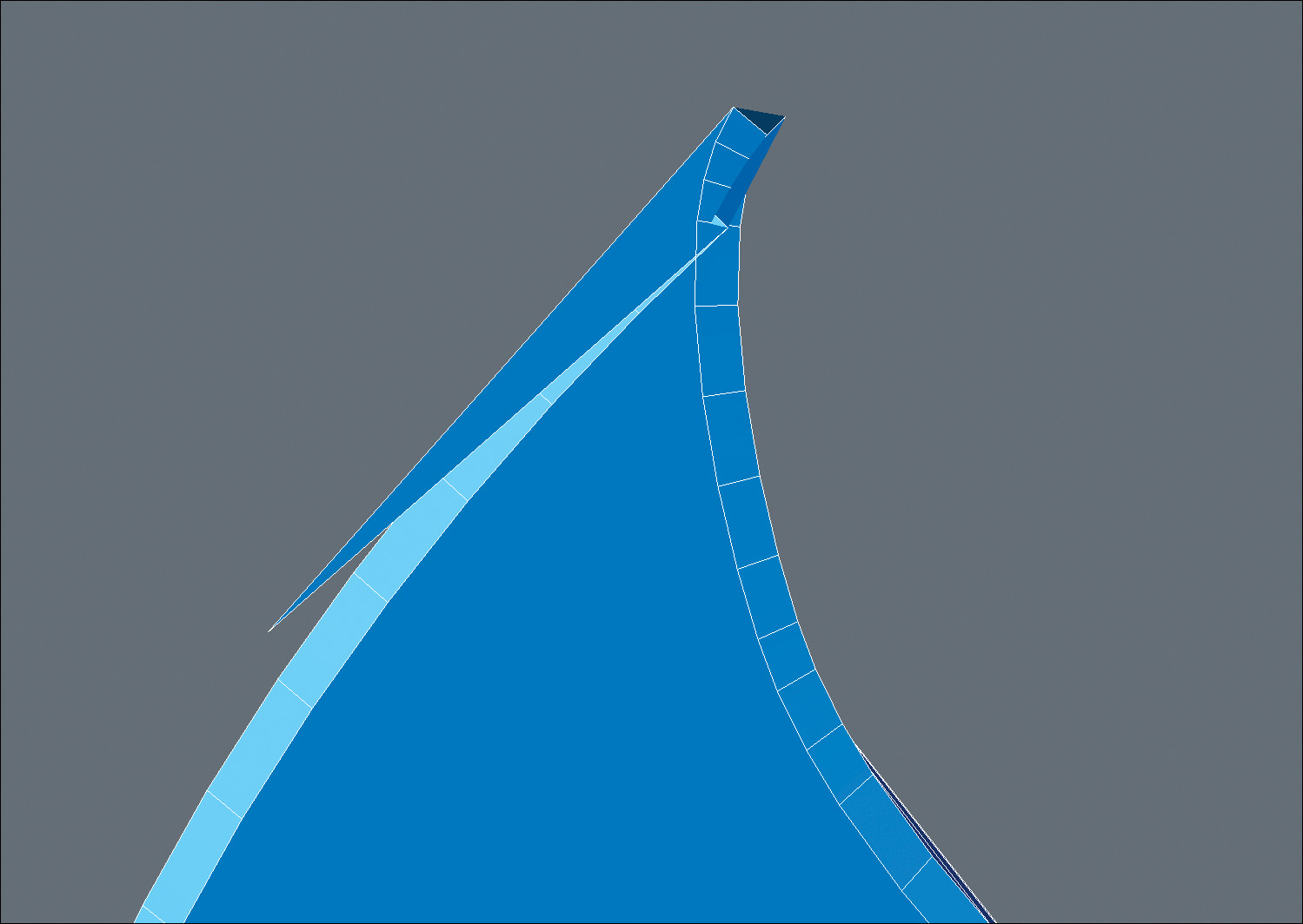
There were a few problem areas on the current Applehead logo that needed to be addressed. The tip of the leaf on the apple shape shown in Figure 7.14 was a bit of a mess, with overlapping polygons caused by the inset of the bevel operation.
[Figure 7.14] This geometry suffers from a common case of overlapping polygons due to the beveled inset.
This issue was easy to fix with a few adjustments to the mesh. By moving some of the points, I quickly cleaned up this issue (Figure 7.15) and moved on to other problem areas. Don’t take the easy way out and either change the amount of bevel you really want or avoid beveling the edges altogether. This issue is an easy fix and worth the time invested.
[Figure 7.15] Simply adjusting the points in the tip solves the issue without having to avoid the desired beveled edge.
Before calling the model final, I always look over every area of the mesh with a fine-toothed comb. If anyone is going to find an issue with my model, I’d rather it be me. With the bevel issues resolved and a detailed survey of the mesh, I had a completed 3D version of the Applehead Factory logo (Figure 7.16).
[Figure 7.16] The completed 3D Applehead Factory logo.

Modeling a 3D Polygonal Object with Seams
Years ago, I was tasked by a client to create a detailed 3D model of a traditional soccer ball (Figure 7.17). After reviewing the storyboards, I was sure that a bump map (an image used to create the appearance of surface detail) on the surface of the sphere wouldn’t produce the seams at a high enough level to hold up under the scrutiny of the extreme close-up shots the animation required.
[Figure 7.17] A soccer ball can be a challenging 3D model without a good technique in place to create the seam pattern.

Fortunately, I was lucky enough to come across an amazing tutorial that took what could have been a difficult task and simplified the steps for me. This technique involves starting with a tessellated primitive sphere (a sphere made up of nothing but evenly spaced triangles), and with just a few steps, you end up with a photo-real, fully detailed, traditional soccer ball model (Figure 7.18).
[Figure 7.18] A tessellated ball (left) is a great base mesh when starting to model a traditional soccer ball. Each patch on the ball was selected and beveled to create the seams (middle). Beveling each patch and assigning surfaces resulted in a photo-real soccer ball (right).

I’ve used this technique anytime I’ve been called on to create a traditional soccer ball over the years, and it always reminds me of how good problem solving can make light work of any challenge.
While creating 3D assets for FunGoPlay (FGP), an online virtual sports theme park for kids, I was tasked with creating another digital model of a soccer ball. This time it was a custom version of a traditional soccer ball that would be used for a close-up shot in a commercial showcasing FGP’s sports gear product line. Once again I used the same technique that had never failed me, and the resulting mesh was created in short order. Figure 7.19 shows a final frame from the commercial that ran on Cartoon Network and Nickelodeon.
[Figure 7.19] This CG soccer ball was created for a FunGoPlay commercial using the same technique discussed earlier.

The FGP virtual world also called for several new digital soccer balls, ranging from the 2009 Teamgeist to the 2010 World Cup Jabulani. I loved the seam pattern on the Jabulani ball (Figure 7.20), so I gladly accepted the challenge to re-create it in 3D.
[Figure 7.20] Our goal in this section is to re-create the paneling of the 2010 Jabulani soccer ball.

Getting Started
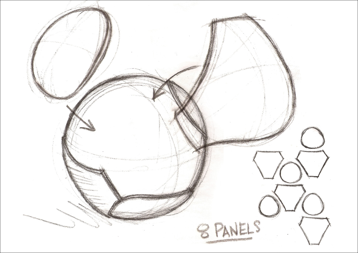
As with any digital modeling project, I started by gathering reference material and carefully studying the design of the ball. I find that loosely sketching out the shapes can be a great way to try to get your head around an object. Figure 7.21 shows how I broke down the ball’s paneling, and I discovered that the Jabulani ball is composed of eight panels that are spherically molded. There are two distinct shapes that make up the eight panels. It’s important that these shapes be exact so that they connect perfectly together.
[Figure 7.21] This rough sketch helped to work out a game plan for how I was going to build each of the eight panels.
It didn’t take long to figure out that starting with a tessellated sphere was not the solution for this unique seam pattern. However, after a few hours, I was able to create the pattern of the ball using spline patch modeling. I accomplished my goal but was left unsatisfied because I was convinced there was a more refined solution that would produce a cleaner topology, and to be quite honest, I wanted to take this opportunity to put my problem-solving skills to the test.
The procedure that follows is the result of a day’s experimentation with the goal of creating easily reproducible results when modeling a 2010 Jabulani soccer ball. By going back and breaking down the model into refined steps, you truly become a better problem solver, and I’d suggest doing the same on your own projects from time to time.
I found that starting with either a segmented or tessellated ball produced undesirable polygon flow, but starting with a tetrahedron (Figure 7.22), a platonic solid primitive, could provide a good base mesh for the Jabulani ball. The polygons that make up a platonic solid are all identical, with the same number of faces meeting at each vertex; thus, all its edges are congruent, as are its vertices and angles.
[Figure 7.22] Starting with a tetrahedron seems odd, but this platonic solid is surprisingly versatile
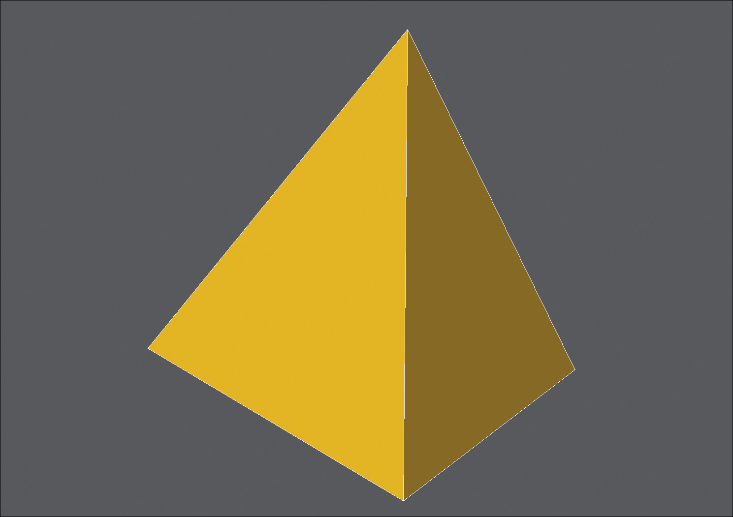
A tetrahedron is a type of pyramid consisting of four equilateral triangles with a flat polygon base and triangular faces connecting the base to a common point. My thought was that the four tips of this pyramid could be a good base for four of the eight panels.
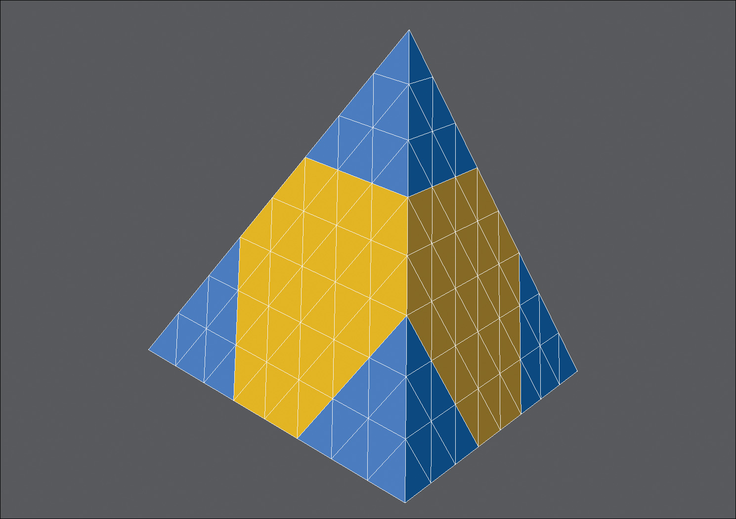
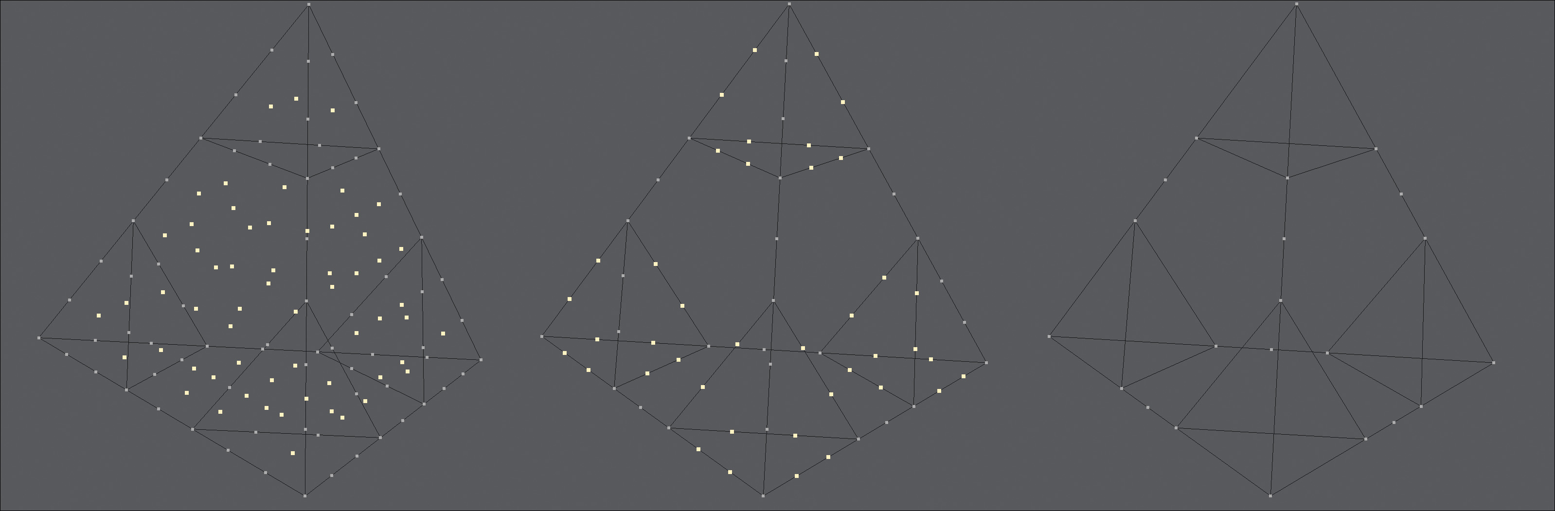
Next, I needed to split the tetrahedron into several sections to allow for reshaping. Instead of measuring or guessing where to split the polygon faces, I subdivided the object into smaller faces that made it easier to work with. The resulting mesh gave each triangle face a poly-count of 64 three-point polygons, with a total object poly-count of 256.
To keep the object manageable, I assigned the tips of the tetrahedron to a new surface group and changed their color so that I could easily see the difference between the polygon islands (groups of polygons). Figure 7.23 shows these tips in blue.
[Figure 7.23] The tetrahedron divided into 256 polygons. Changing the surface of the tips makes it easier to define each section of the base mesh.
With the tetrahedron sectioned off, I needed to remove the excess polygons. I simply selected the polygons that make each section and merged them into one. It was important to merge only those polygons that were on the same plane, not the entire tip. Figure 7.24 shows the base mesh after merging each group of polygons.
[Figure 7.24] Each poly-group is merged to refine the mesh by removing unneeded geometry.

I know I just finished making those extra polygons, but that step was only to help create the shapes I now have. It prevented me from having to do any measuring, and I knew that all of the shapes that had been created up to this point were identical.
House Cleaning
Some 3D software may leave unwanted points behind after merging. I like to keep my work area clean as I go, so I always remove any points that are not connected to any polygons when constructing a mesh in this fashion.
There were still a number of points that needed to be removed from the tip portions of the object, so I selected the 12 unneeded points per tip (a total of 48 points), which were located along the base edges, and removed them. The process of cleaning the mesh is shown in Figure 7.25.
[Figure 7.25] These selected points are no longer connected to any polygons and can be removed (left). Although these points are connected to polygons, they are no longer needed for us to continue on to the next step (middle). The resulting mesh is much cleaner with the points removed (right).
Layout Foundations
To get the base mesh closer to the proper shape I was after, I needed to bring the four points at the very tips of the tetrahedron down to the same edge that bordered the base of the tips. I selected the four tip points and moved them so that they became flush with the tips’ base edges. Figure 7.26 shows the result of the moved points.
[Figure 7.26] The four points at the tips of the tetrahedron are selected in preparation of the next step (left). The selected points are moved flush to the tips’ bases (right).

My goal was to end up with the cleanest polygon flow possible, so I reconfigured the geometry that makes up the tips. To do this, I split the edges that make up the base of the tip sections, working on one tip section at a time. I selected the bordering edges and added a point in the center. I did this for all four tip sections before moving on. For each section, I created new edges that connected the new points to the center point of each tip. Figure 7.27 shows these new edges.
[Figure 7.27] The points selected here (left) were the result of adding points to the three bordering edges of the tip polygons. These three new edges (right) were generated to help aid in reconfiguring the tips’ topology.

All that was left for the tip sections was to merge the polygon pairs, so that I ended up with a diamond shape configuration (Figure 7.28). Reconfiguring the tip sections may seem trivial right now, but it will drastically change the final topology of the object for the better. Trust me!
[Figure 7.28] Three sets of triangle polygons were merged into these three diamond-shaped quads.

I made sure that all four tip sections had been reconfigured before moving on to the next step. With all of the tips in the proper configuration, I started to create the topology needed for the center sections of the base object.
I knew I wanted to split the center sections into smaller components. Doing this would enable me to control the polygon flow of the final mesh. I started by selecting the two center points and splitting the center sections right down the middle, creating a new edge (Figure 7.29).
[Figure 7.29] These two points (left) are selected in preparation of splitting the center polygon. An edge is created, connecting the two selecting points (right).
I then selected the new edge that was just created and added a new point in its center. I added the points that were on the edges that border the center section to my selection and created new edges, splitting the center area into four faces. Figure 7.30 shows the result of the split.
[Figure 7.30] A new point is added to the center of the newly created edge (left). The two points along the border of the center patch are added to the selection (middle). Edges are created to connect the selected points (right).

I repeated the steps on the lower portion of the mesh by selecting the center point and the points bordering the tips on the other side of the triangle, creating two more edges and thus splitting the center area into six polygons (Figure 7.31).
[Figure 7.31] The same edges are needed for the lower portion of the mesh. These points are selected in preparation for new edges (left). Edges are created to connect the selected points on the lower part of the mesh, resulting in the center patch being made up of six polygons (right).

I once again repeated the steps until all four of the center sections were identical; each contained six polygons. I still wanted to divide the center areas into more polygons, so I selected the edge loop that bordered one of the tips and split it down the center, creating two bands around the tip. Figure 7.32 shows the two bands around the base of the tip.
[Figure 7.32] The edge loop bordering the tip geometry is highlighted here in pink (left). This band of polygons has been split down the center, creating two sets of loops (right).

Satisfied with the results, I repeated these steps for the remaining tips (Figure 7.33).
[Figure 7.33] New bands are created around the remaining tips.
Believe it or not, the tedious portion was then complete. What I currently had was a magic configuration that would allow me to create the Jabulani soccer ball I was after. This base mesh consisted of 60 four-point polygons (60 quads).
It was important to go through these steps so that the underlying topology would provide optimal results. There are several ways I could have divided the base object to end up with the current state of the mesh, but I found this to be the most efficient way to ensure that all the segments were evenly spaced. This even spacing guarantees a more refined final mesh, which should be a goal of any model you create.
Final Stages
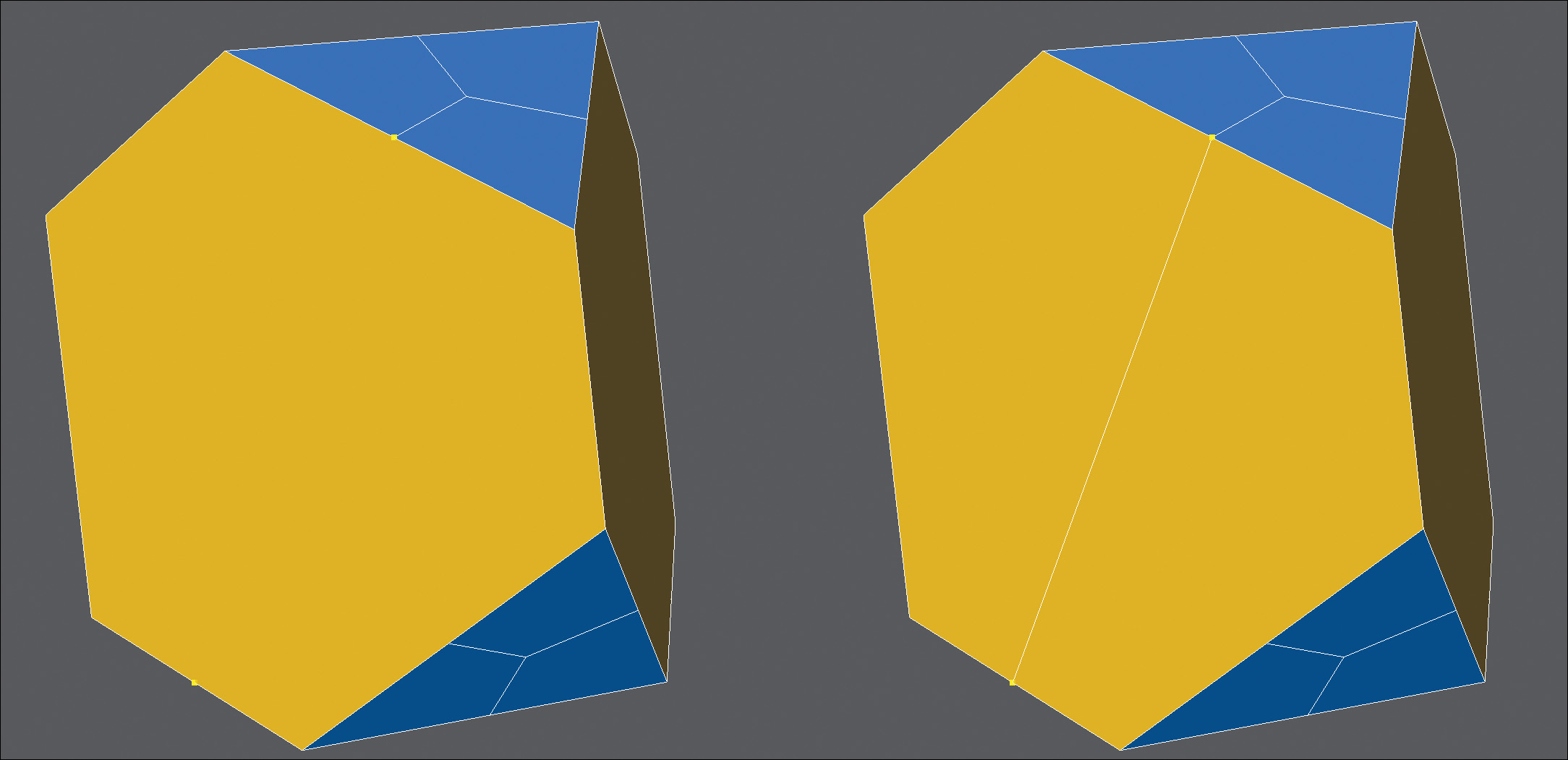
The finish line was in sight. To speed up selecting individual sections in future steps, I gave each of the center sections its own surface (Figure 7.34). Trivial steps like this are often overlooked by artists, costing them lost time on a production.
[Figure 7.34] The center patches are given unique surface groups and assigned different colors to aid in future steps.

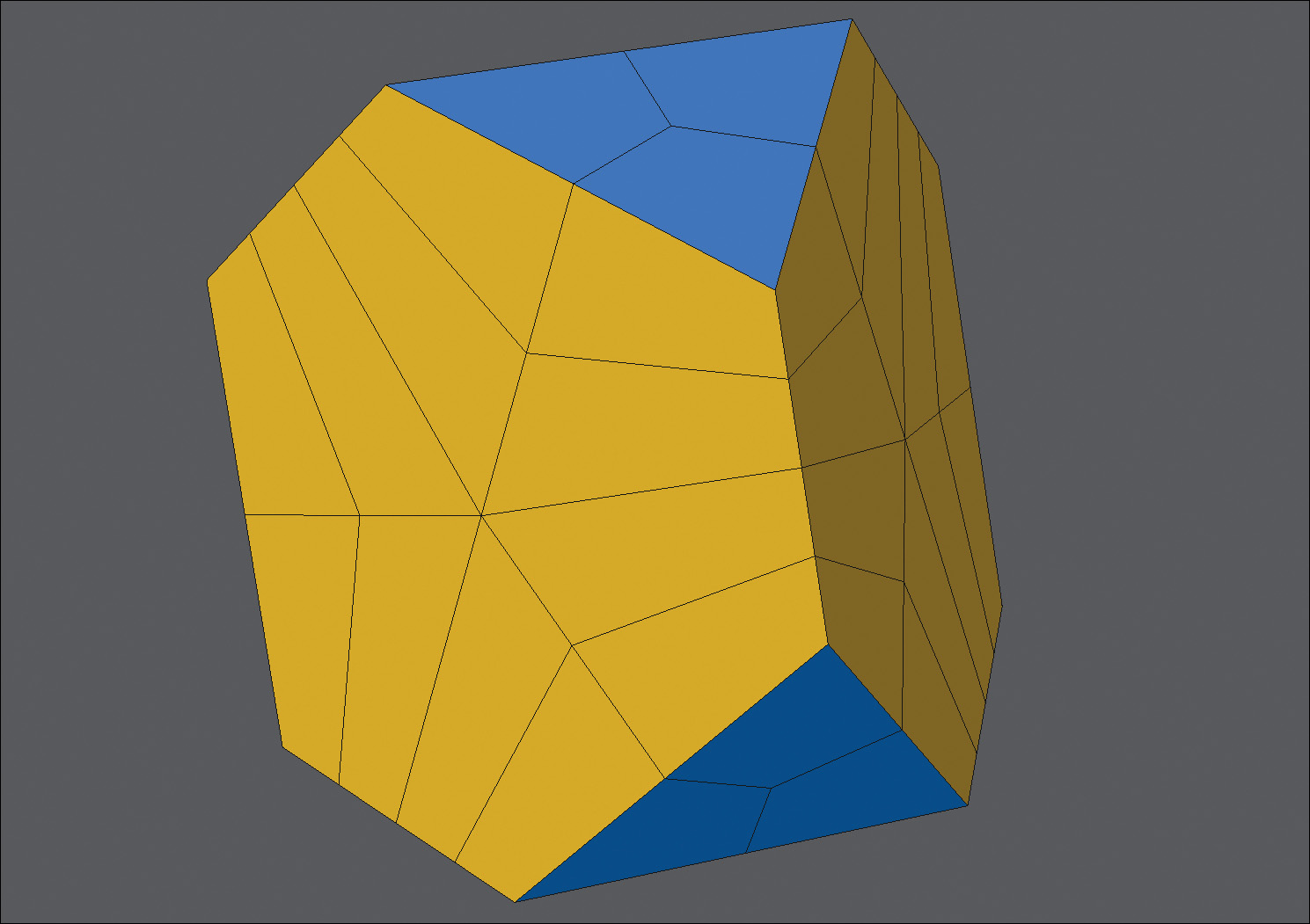
Before I was ready to convert this geometric shape into a sphere, I wanted to increase the geometry a bit, so I subdivided the mesh into 960 quads. With a denser mesh and more polygons to work with, I performed a little magic! I wanted to deform this mesh into the shape of a sphere, so I used a deformation tool that shrink-wraps any geometry into a sphere. The result, shown in Figure 7.35, was a perfect sphere with the topology that I mapped out earlier.
[Figure 7.35] The base mesh is subdivided in preparation of deformation, which will occur in the next step (left). The result of deforming the mesh into the shape of a sphere (right).

Without the initial preparation, I could have generated a ball object, but the underlying polygon flow would have been less than desirable.
The sizes of the tip panels were too small. I wanted to increase them so that they were in proportion to the center panels. I selected the polygons that made up the tip sections and expanded the selection so that four new polygon bands were part of each of the tip’s selection. I changed the surface of the selected polygons so they all used the tip surface. Figure 7.36 shows the result.
[Figure 7.36] The tip patches’ surface groups are expanded to match the size of the real-world patches on the Jabulani ball.
The object had a low polygon count, which would reveal faceting when viewed up close. That wasn’t going to work. I wanted this soccer ball to be seen at much higher resolutions, so I subdivided it again (Figure 7.37).
[Figure 7.37] The mesh is subdivided again.

I could see that I had accomplished my goal of creating the proper paneling of a Jabulani ball, but it was missing the seams that would allow the edges of the paneling to catch light. Adding this level of detail to a model will only enhance a mesh and add more realism to the final render.
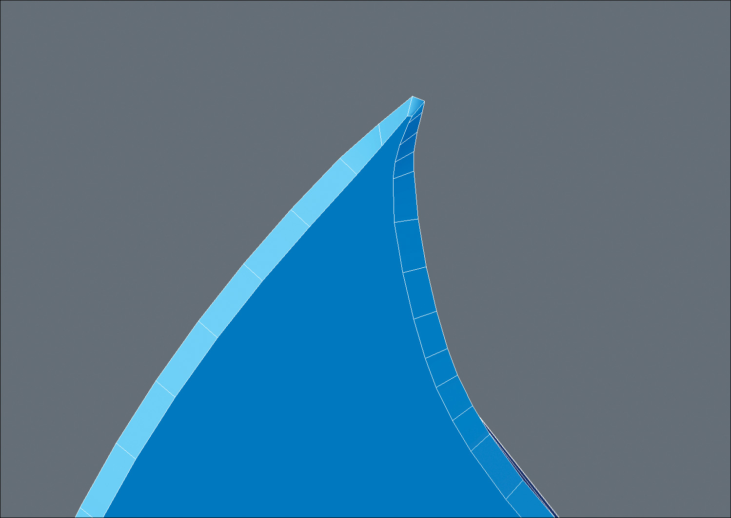
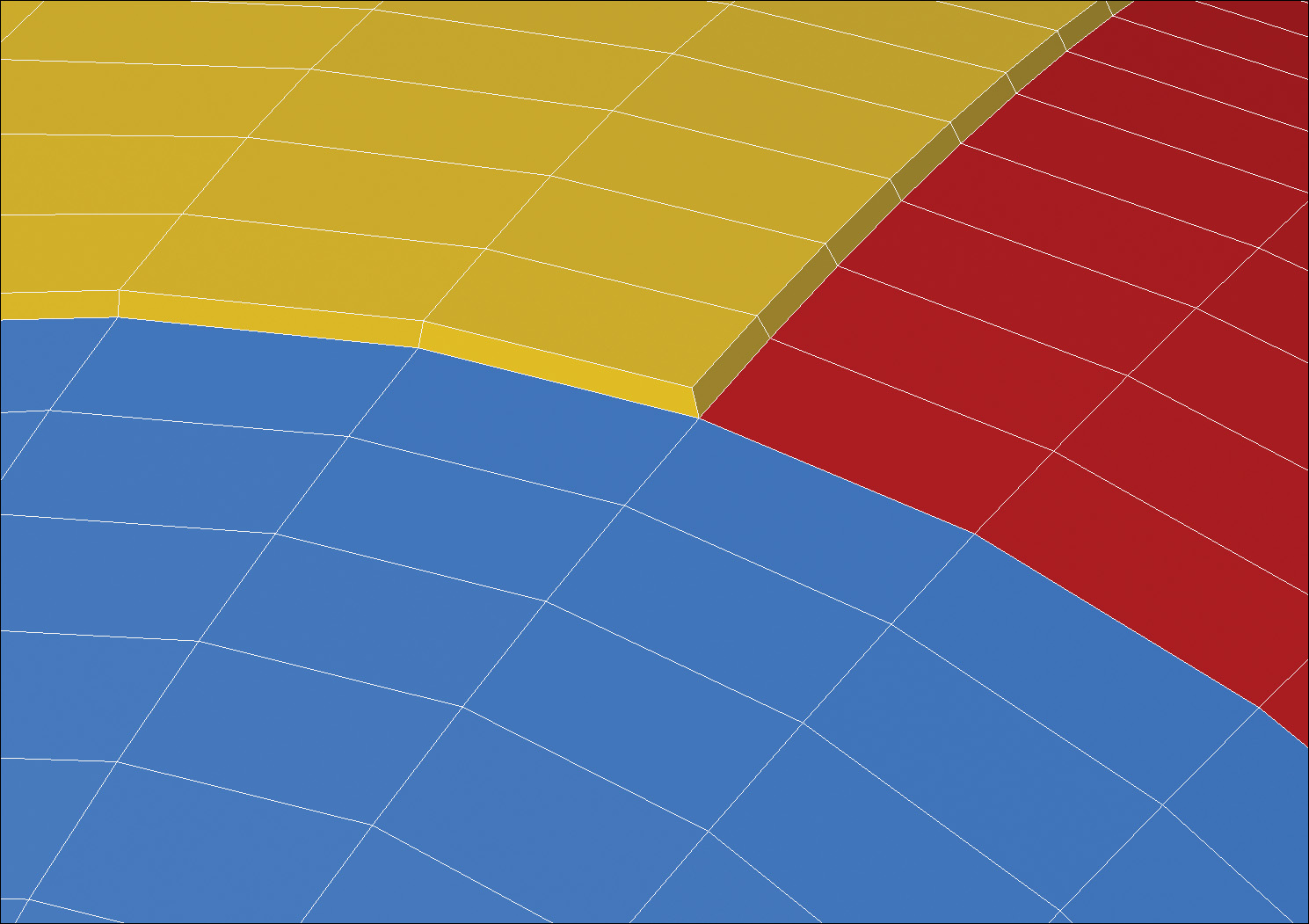
To create the seams on the ball, I created a beveled edge around each patch, as shown on the yellow polygons in Figure 7.38. Because I planned ahead and created a different surface group for each patch, it was an easy task. I selected the polygons that made up one of the center patches and beveled it using a small shift and inset value.
[Figure 7.38] The “yellow” patch is selected and beveled with a small shift and inset to start the creation of the seams in the ball.
I deselected the polygons and repeated this process until all eight patches (triangle centers and tips) had been beveled (Figure 7.39).
[Figure 7.39] Each patch is given a bevel to complete the seam work.

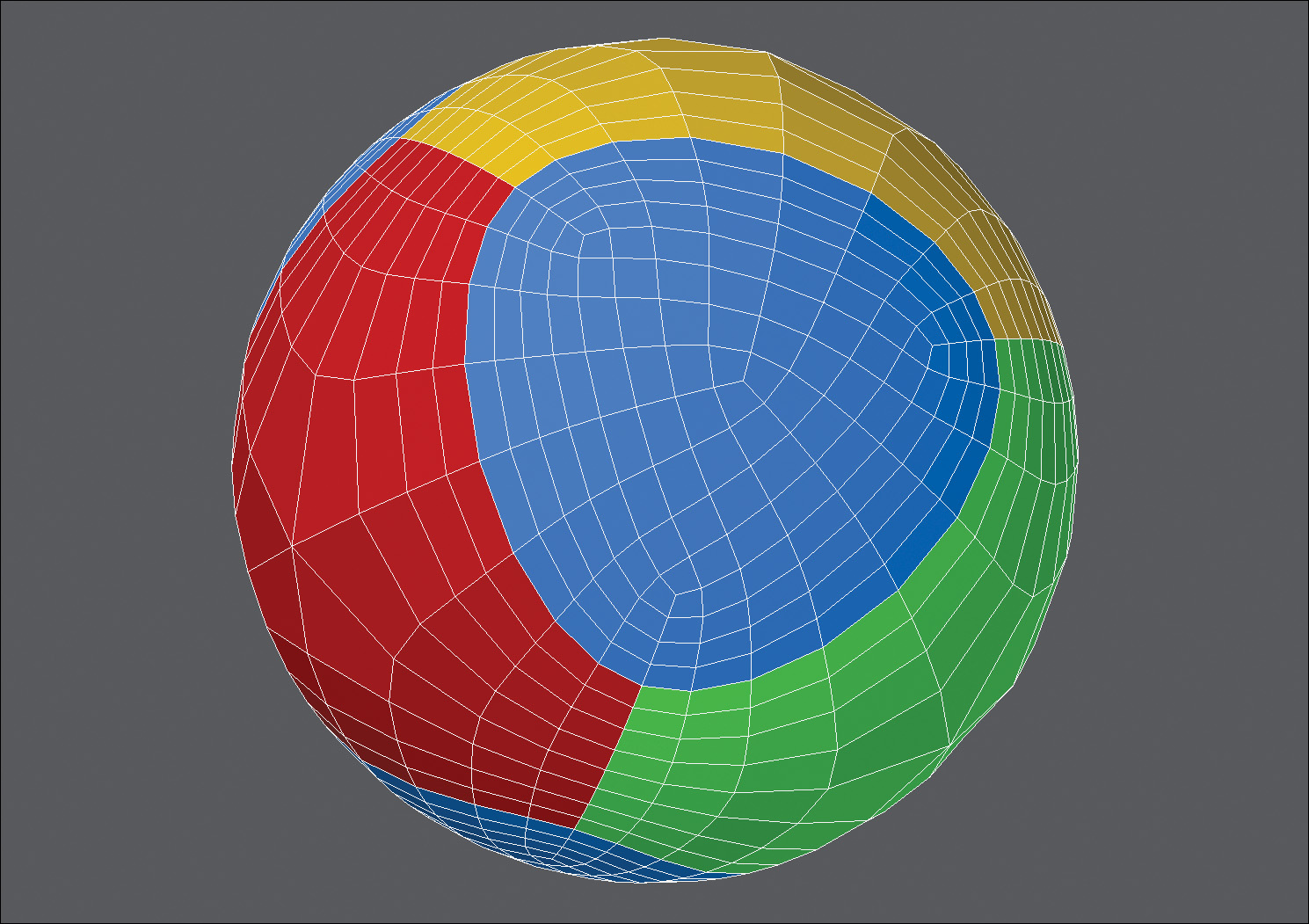
With the seams in place, I subdivided the mesh one more time to increase the poly-count and smooth out the seams’ edges so they didn’t appear unnatural and sharp.
I changed the surface attributes for all the panels that made up the object to solid white instead of creating a new surface group so that I could get a better look at the final mesh (Figure 7.40). Changing the color of the existing surfaces gives me the ability to go back at a later time and edit each patch independently by selecting polygons by surface.
[Figure 7.40] The mesh is subdivided again to smooth out the newly created seams and all of the surface group’s colors are changed to white.

Goooal!!!
There you have it! With a bit of preplanning and taking a little extra time in the beginning, I not only successfully completed what I set out to create, but I set myself up with clean polygon flow and patches that are mathematically identical for the eight-panel design that makes up the 2010 World Cup Jabulani soccer ball.
Although I invested an entire work day developing this technique, using it allows me to generate this soccer ball in less than five minutes, whereas the spline patch modeling method took over an hour, and the topology wasn’t as accurate as I would have liked it to be.
For every digital model you create, your goal should be to deliver a clean mesh with optimal topology. Sometimes revisiting an object you’ve already created and thinking outside the box can lead to new techniques that shave hours off of your future modeling sessions.