CHAPTER 9
Print It! with 123D Meshmixer and MakerBot
In this chapter we’ll use the Analysis tools in Meshmixer’s Modify area to prepare an .stl file for printing. Then we’ll hollow the file out in Meshmixer’s Print area, send it to MakerBot Desktop to set preferences, and print it. We’ll also look at third party printing options.
General 3D Printing Information
All printers—from consumer models that churn out plastic trinkets, to commercial ones that make metal turbines—read a digital model. You can create that model with any software, but you can’t print it from a file saved in the software’s native format. The file must be converted into a format the printer can read. The most common printable format is an .stl file, which is basically a shell containing a mesh model.
The .stl file and printer need software to communicate between them. The software slices the digital model into cross-sections, hence this software is also called a “slicer.” Then the printer melts and deposits filament (plastic thread) in successive layers corresponding to the cross-sections. The result is a physical print with the digital model’s form. This process is additive, as opposed to the subtractive process that a CNC router utilizes when cutting shapes from sheet material.
Consumer printers use a technology called fused deposition modeling. An extruder (also called a printer head) deposits the filament onto a build plate (also called a printer bed). The extruder is attached to a gantry, which is a system of rods and belts that moves along rails. The gantry moves the extruder in three directions: left to right along the x axis, forward and backward along the y axis, and up or down along the z axis (see Figure 9-1). A printer’s resolution is the thickness of each layer, measured in microns. Thin layers provide a more detailed print than thick ones. The thinner the layer, the lower the resolution number.
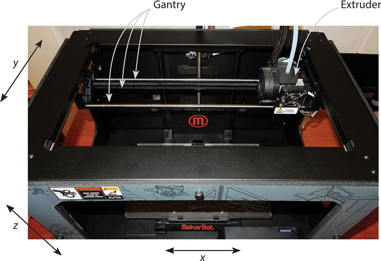
Figure 9-1 The extruder and gantry on a MakerBot Replicator 2. The extruder moves along the x, y, and z axes to deposit filament.
Printing time can range from 20 minutes to over a day, depending on the model’s size, complexity, speed setting, and printer capabilities. A 1”×1” model on MakerBot’s “standard” setting prints in about 25 minutes. The amount of filament used depends on the infill setting; that is, how much material fills the model. You can set a model to print hollow, solid, or any percentage in between.
Overhangs, Supports, Rafts, and Bridges
A model needs to be supported while printed (see Figure 9-2). Overhangs, which are parts of the model that have empty space below them, present a challenge. Additive printing creates thin vertical supports, or layers of filament, to hold overhangs up while they’re being formed. At the bottom of the support is a raft, which is a latticed peel-away layer. Bridges are horizontal supports stretched between gaps to hold up construction above the gap. Slicing software generates default supports, rafts, and bridges, but you can finesse by adding, deleting, or moving them to other locations. After the print is finished, supports are removed by snapping or cutting them off or by dissolving them.
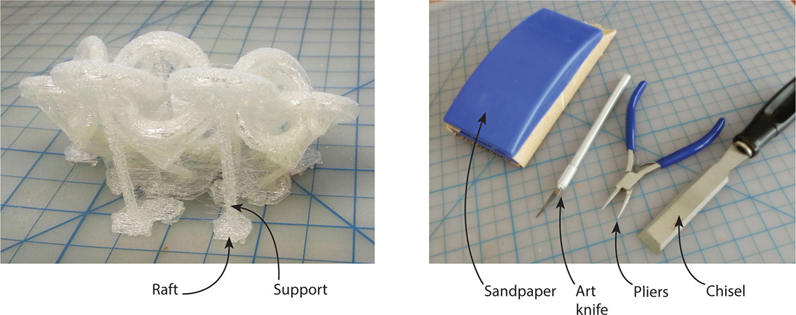
Figure 9-2 Supports are printed to hold up overhanging parts of the model. Here they hold up bracelet links. Tools may be needed to remove them. A pliers, craft knife, and sandpaper are helpful. A chisel can remove a stubborn print from the plate.
The MakerBot
The MakerBot is a high-end consumer desktop printer that’s compatible with Windows, Mac, and Linux operating systems. It is closed source, meaning information about its physical design and user interface is not shared. As of this writing, its models are fifth generation and non-self-serviceable. Early models had wood frames, but now they are steel-framed and sized from compact to extra large. You can view models currently sold at www.makerbot.com. Most MakerBots have one extruder. The experimental models have two, enabling the printing of two-color parts. All have different features, such as Wi-Fi connectivity, onboard camera, printed resolution, type of filament used, and heated or unheated build plate. A comparison chart is found at http://store.makerbot.com/compare. Most have a paper-thin 100-micron (0.0039” or 0.1 mm) resolution. This produces a smooth finish that doesn’t need sanding or other post-production treatment. The Mini has a 200-micron resolution.
When setting the MakerBot up, place it on a sturdy table or desk in a well-ventilated area with no direct drafts (cool air affects the print). It generates noise, heat, and odor, so you might consider that when choosing a location. All models require some assembly, and all except the Mini require leveling the build plate, meaning it must be positioned parallel to, and the correct distance from, the extruder. The Mini is the simplest model (see Figure 9-3). Its few pieces that need assembly snap into place and its filament spool is smaller than those for other models.
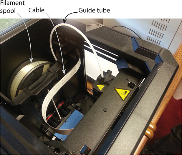
Figure 9-3 The top of a MakerBot Mini. Visible are its filament spool, guide tube, and cable.
MakerBots come with a printed guide, but you may find it helpful to download it to a tablet for easy viewing during the assembly (see Figure 9-4). All guides are at www.makerbot.com/support/guides/. My YouTube channel has two videos showing how to set up a Replicator 2.
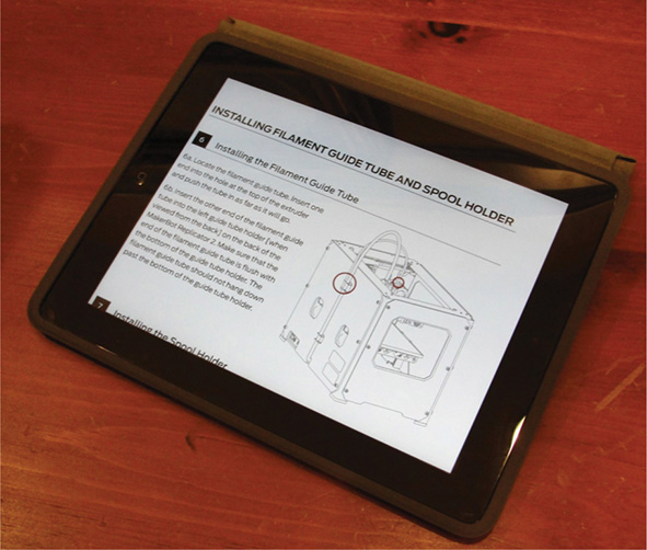
Figure 9-4 Download a guide to a tablet for easy viewing during assembly.
The MakerBot plugs into a USB port on your computer, just like any other peripheral (see Figure 9-5). After 50 hours of use, lubricate the threaded rod and idler pulley by wiping them with a clean, lint-free rag and some PTFE-based grease.
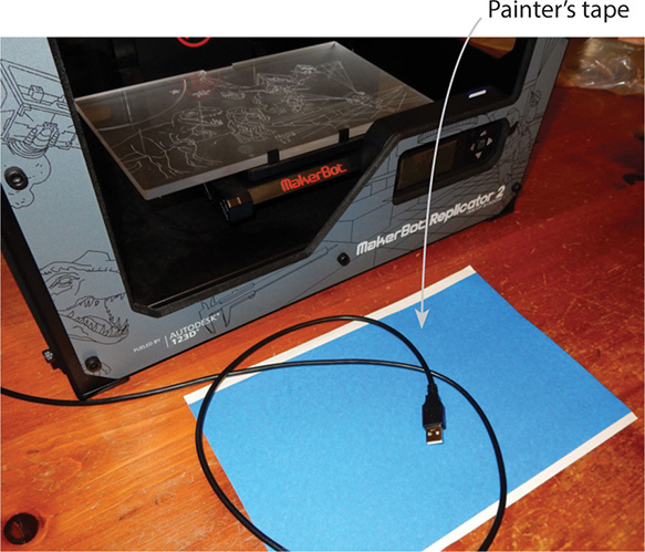
Figure 9-5 The Makerbot plugs into a computer’s USB port. Here, its USB plug is resting on painter’s tape used to cover the build plate.
Adherence to the Build Plate
The print must adhere to the build plate while under construction, but sometimes it adheres too much. Here are some suggestions to facilitate removal:
![]() Cover the build plate with painter’s tape. Buy the type sold as large pieces, not strips. It must be placed smoothly onto the plate, with no wrinkles or creases.
Cover the build plate with painter’s tape. Buy the type sold as large pieces, not strips. It must be placed smoothly onto the plate, with no wrinkles or creases.
![]() Spritz the build plate very lightly with hair spray. Just one push of the button is enough; more will make the plate slippery. Let it dry before printing. Clean with water and a lint-free rag.
Spritz the build plate very lightly with hair spray. Just one push of the button is enough; more will make the plate slippery. Let it dry before printing. Clean with water and a lint-free rag.
![]() Use a craft spatula, putty knife, or chisel to remove the print.
Use a craft spatula, putty knife, or chisel to remove the print.
Some Makers replace the acrylic plate with a glass plate because acrylic tends to warp after heavy usage, impeding adherence. You can find one on Amazon.
MakerBot Software and Firmware
The software that communicates your printing preferences is called MakerBot Desktop, and it is used for all generations and models of MakerBots. Download it at www.makerbot.com/desktop. Owners of older MakerBots should be aware that as you click through the install screens you’ll see text saying the software is for fifth-generation machines. But eventually a selection window for your machine will appear (see Figure 9-6). This software is frequently updated, and notices are sent via e-mail. Firmware, which runs the printer itself, is preinstalled on the motherboard, and is also frequently updated. A firmware update notice will appear when you open MakerBot Desktop, but you can also update it by clicking Devices | Upload Firmware on the menu bar (see Figure 9-7). The printer needs to be plugged in and turned on to do this.
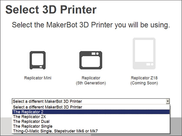
Figure 9-6 Owners of pre-fifth generation MakerBots can select their machine through this screen.
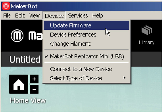
Figure 9-7 Update the motherboard’s firmware through the MakerBot Desktop menu bar.
Filament
Filament is a long string of material wound around a spool (see Figure 9-8). MakerBot’s filament is made of polymer (plastic). It’s nontoxic but not food safe. If you want to print beverage containers, consider printing a mold and casting a food-safe material inside it. Store filament in watertight containers with desiccant packets because humidity ruins it.
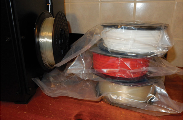
Figure 9-8 MakerBot filament is a long string of plastic wound around a spool. Here, a spool is shown attached to the printer. Three unused spools are kept in their original sealed plastic for protection against humidity.
MakerBot makes four types of filament: PLA, ABS, flexible, and dissolvable, and either 1.75mm or 1.8mm wide. Some MakerBot printers use PLA; others use ABS. All are polymer and optimized for MakerBot printers, so other filament materials are not recommended.
![]() ABS This is oil based and good for very detailed prints. It has tight tolerances and is most suited for the experimental printers. It can be used with flexible filament. ABS emanates strong fumes, so print in a well-ventilated area. It requires a heated build platform and is available in multiple colors.
ABS This is oil based and good for very detailed prints. It has tight tolerances and is most suited for the experimental printers. It can be used with flexible filament. ABS emanates strong fumes, so print in a well-ventilated area. It requires a heated build platform and is available in multiple colors.
![]() PLA This is corn based, emanates mild fumes, doesn’t warp as much as and is harder than ABS. It’s also very shiny. PLA is available in multiple colors, including translucent, fluorescent, glittery, and metallic. It’s good for beginners because it’s easy to use and performs well on most prints. It adheres to both acrylic and tape.
PLA This is corn based, emanates mild fumes, doesn’t warp as much as and is harder than ABS. It’s also very shiny. PLA is available in multiple colors, including translucent, fluorescent, glittery, and metallic. It’s good for beginners because it’s easy to use and performs well on most prints. It adheres to both acrylic and tape.
![]() Flexible This is stretchy. It adheres to acrylic but not to tape. Finished prints can be modified by soaking them in hot water until they become translucent.
Flexible This is stretchy. It adheres to acrylic but not to tape. Finished prints can be modified by soaking them in hot water until they become translucent.
![]() Dissolvable This is used with ABS filament on a heated build plate. It needs to be soaked in a limonene (chemical) bath to dissolve. Use it as a solid infill, as a soluble mold for poured materials, or for removable support structures (which results in a print with a smooth finish instead of the small scars that result from cutting off supports). It adheres well to DuPont Kapton tape, which is similar to electrical tape.
Dissolvable This is used with ABS filament on a heated build plate. It needs to be soaked in a limonene (chemical) bath to dissolve. Use it as a solid infill, as a soluble mold for poured materials, or for removable support structures (which results in a print with a smooth finish instead of the small scars that result from cutting off supports). It adheres well to DuPont Kapton tape, which is similar to electrical tape.
The finished product can be primed, painted, sanded, machined, glued, and drilled. This enables you to print large models in separate parts and glue or pin them together.
Export an .stl File from the 123D Apps
Design, Make, and Catch export files in their native formats directly to Meshmixer (see Figure 9-9), where they can be altered and then converted into an .stl format. Design even lets you select and send just part of the model; click the appropriate Meshmixer icon on the glyph that appears upon selection. Design also exports .stl files directly to your desktop. The CNC Utility app saves a file to your online 123D account, where you can download it for manual import into Meshmixer. Tinkercad saves .stl files to your computer.
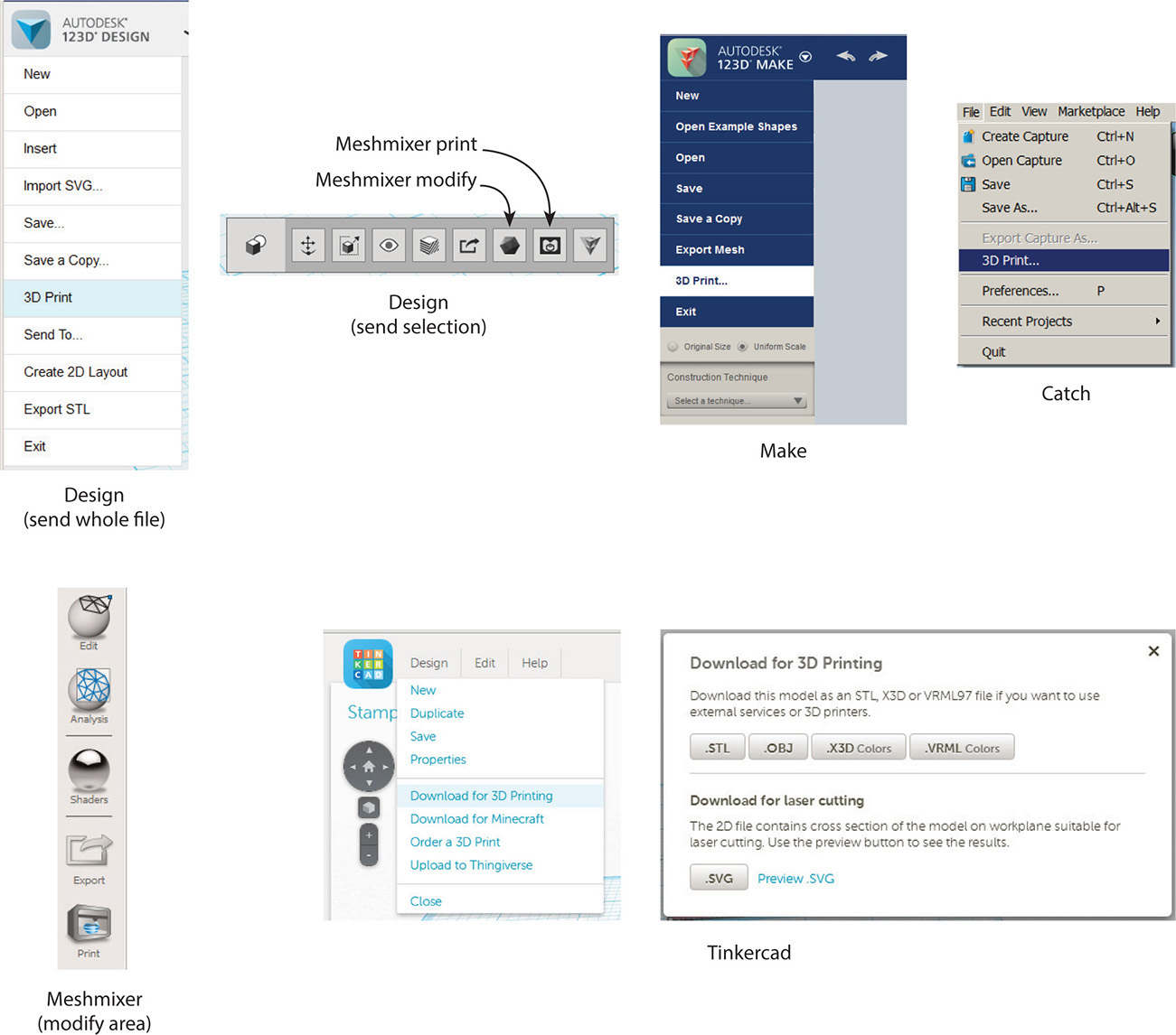
Figure 9-9 Most 123D files can be sent from their apps directly to Meshmixer. Tinkercad downloads .stl files to your desktop.
.stl files can also be downloaded from your online 123D account and imported manually into Meshmixer. This is useful if Meshmixer crashes when a native 123D format file is sent directly to it (this sometimes happens with large Catch files). To retrieve an .stl file, click Models, click the model’s thumbnail, click the Edit/Download button, and click Download 3D Models (see Figure 9-10). You’ll get both an .stl and .obj file.
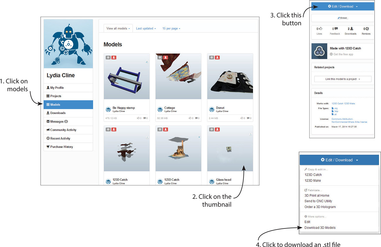
Figure 9-10 Files saved online can be downloaded in .stl and .obj formats.
You Need a Printable File
Not all .stl and .obj files are printable, even if they look good in the CAD application. To be printable, a model must
![]() Have no holes in its mesh. This is called “watertight,” meaning if you poured water into it, none would leak out. If the model has holes, the printer won’t know what to fill.
Have no holes in its mesh. This is called “watertight,” meaning if you poured water into it, none would leak out. If the model has holes, the printer won’t know what to fill.
![]() Be solid. The model must be one solid piece with no surface intersections. Boolean Union multiple pieces together.
Be solid. The model must be one solid piece with no surface intersections. Boolean Union multiple pieces together.
![]() Be manifold. This means that each edge must connect to exactly two faces (a non-manifold edge connects to three or more).
Be manifold. This means that each edge must connect to exactly two faces (a non-manifold edge connects to three or more).
![]() Have front-facing polygons. The normals (fronts) must face out. The faces cannot overlap or have overlapping vertices, either.
Have front-facing polygons. The normals (fronts) must face out. The faces cannot overlap or have overlapping vertices, either.
If any defects exist, the printer won’t be able to read the file, and error messages will appear when you try to send it to MakerBot Desktop. It’s best to address these issues in the original app. Meshmixer’s analysis feature will help you fix them enough to be printable, but depending on what and how much needs fixing, the model may change in ways you didn’t expect. Preview before spending time and plastic making it.
Design Considerations
Unlike a digital CAD model that exists as pixels on a screen, a physical print has material properties and is subject to gravity. Planes have meaning to CAD software, but not to a 3D printer (see Figure 9-11).
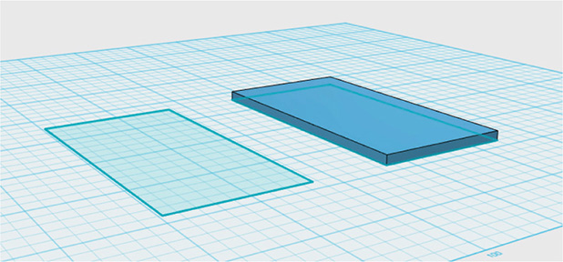
Figure 9-11 A plane can exist on a computer screen, but thickness must be added to make it printable.
Digital models are often scaled down before printing, but a part that is scaled down too much won’t print. Features that start thin or small get thinner or smaller and must be arbitrarily thickened or removed. Make decisions about what features to show and how to show them. This is especially important when printing with a third party, because assumptions will be made on what to change, and those assumptions may be wrong. So always be cognizant of the design’s suitability for printing if a print is your end goal. Here are tips for making a printable model:
![]() Leave plenty of clearance (space) between moving or separate parts (see Figure 9-12). Otherwise, they’ll fuse together when printed. This applies to features such as links, gears, and cogs. A clearance of 0.4mm to 0.5mm on all sides should work. Parts that must fit snugly together need between 0.1mm and 0.25mm clearance on all sides to ensure they don’t easily come apart.
Leave plenty of clearance (space) between moving or separate parts (see Figure 9-12). Otherwise, they’ll fuse together when printed. This applies to features such as links, gears, and cogs. A clearance of 0.4mm to 0.5mm on all sides should work. Parts that must fit snugly together need between 0.1mm and 0.25mm clearance on all sides to ensure they don’t easily come apart.
![]() Account for plastic shrinkage when making the digital model. ABS filament shrinks about 2 percent. PLA shrinks about 0.2 percent, so it’s a better choice when dimensional accuracy is important. No features should be less than 2mm in size.
Account for plastic shrinkage when making the digital model. ABS filament shrinks about 2 percent. PLA shrinks about 0.2 percent, so it’s a better choice when dimensional accuracy is important. No features should be less than 2mm in size.
![]() Simplify complicated assemblies in the original app before printing, because fine tuning may be difficult or impossible inside Meshmixer or MakerBot Desktop. Scale the model to its final printed size in the original app, too.
Simplify complicated assemblies in the original app before printing, because fine tuning may be difficult or impossible inside Meshmixer or MakerBot Desktop. Scale the model to its final printed size in the original app, too.
![]() Set the digital model’s units to mm or convert it to mm in the original app before printing, because that’s the unit MakerBot Desktop understands. Using mm will also enable you to scale the model precisely inside that software, if you need to scale it there.
Set the digital model’s units to mm or convert it to mm in the original app before printing, because that’s the unit MakerBot Desktop understands. Using mm will also enable you to scale the model precisely inside that software, if you need to scale it there.
![]() Pointed features cannot be printed. They must be thickened.
Pointed features cannot be printed. They must be thickened.
![]() Thin-walled models may break during printing or shipping, or they might not print at all. This also applies to models that have a large mass connected to a thin one. .8 to 1mm generally works; 2mm is safest.
Thin-walled models may break during printing or shipping, or they might not print at all. This also applies to models that have a large mass connected to a thin one. .8 to 1mm generally works; 2mm is safest.
![]() When unsure if something can be printed, print a small, quick sample. Alternatively, send small, cheap models to a service bureau to study the results.
When unsure if something can be printed, print a small, quick sample. Alternatively, send small, cheap models to a service bureau to study the results.
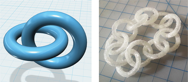
Figure 9-12 Leave enough clearance between separate parts so they don’t fuse together when printed.
Meshmixer’s Two Areas: Modify and Print
Meshmixer has two areas:
![]() Modify This area enables you to significantly alter the appearance of the model, mash it up with other models, and add parts from a built-in library. Read Chapter 6 to learn more about these features. This area also contains analysis tools that study the model’s suitability for printing, generate supports, and find the optimal position for construction.
Modify This area enables you to significantly alter the appearance of the model, mash it up with other models, and add parts from a built-in library. Read Chapter 6 to learn more about these features. This area also contains analysis tools that study the model’s suitability for printing, generate supports, and find the optimal position for construction.
![]() Print This area has options for 3D printing. Here you can also hollow out the model with one click and thicken its features. Then either send it to MakerBot Desktop to print with your own machine or upload it to a third party service bureau.
Print This area has options for 3D printing. Here you can also hollow out the model with one click and thicken its features. Then either send it to MakerBot Desktop to print with your own machine or upload it to a third party service bureau.
A file is sent from the Modify to the Print area by clicking the Print icon in the Modify area’s vertical panel.
Import the Glass Head

We’re going to print the glass head made in Chapter 5. Choose Import from Meshmixer’s launch screen to bring in an .stl file (choosing Open brings in a .mix file). Navigate to the .stl file and bring it in (see Figure 9-13). Meshmixer imports .obj, .ply, and .amf files as well. Note the vertical menu panel on the left. It contains the Analysis and Print icons we’ll be using. Press and hold the spacebar to access the navigation panel (see Figure 9-14). This contains icons to zoom, pan, orbit, and fit. You can also orbit by pressing the mouse’s scroll wheel down.
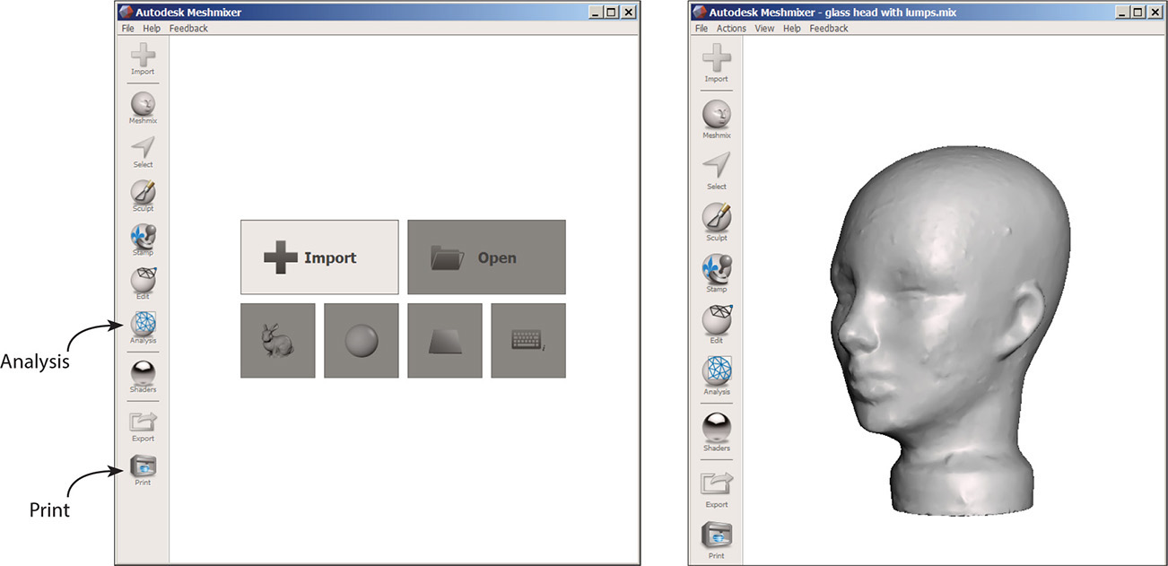
Figure 9-13 The Meshmixer launch screen and the imported glass head
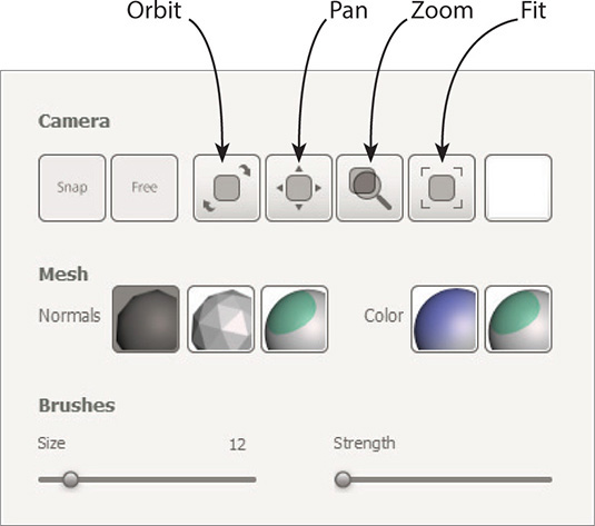
Figure 9-14 Press and hold the spacebar to access the navigation panel.
The model enters in the Modify area, where I made some quick changes to it. Specifically, I removed surface lumps with the Robust Smooth brush, used Plane Cut with the DelRefine Fill to slice the bottom straight, and used Extrude to make the base taller and more sturdy. A model should be as finished as possible before running the analysis tools on it.
Analyze the Glass Head
Click the Analysis icon now. It contains tools that study the model for printing suitability (see Figure 9-15). Unsuitable features need to be fixed before sending the file to MakerBot Desktop. Let’s run each tool on the model.
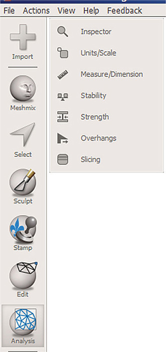
Figure 9-15 The Analysis icon contains tools that study the model for printing suitability.
Inspector
Click this to find holes in the model (see Figure 9-16a). Pins appear at the holes, and you have the option of fixing them individually or just clicking Auto Repair All. Fixing them individually gives more control over each repair; clicking Auto Repair All is faster, but may have unpredictable results. Such repairs are discussed in Chapter 6. Figure 9-16b shows a model that clearly needs a lot of fixing. No pins appear on the glass head, so click Done to exit.
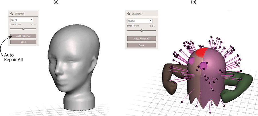
Figure 9-16 (a) Click the Inspector tool to find holes in the model. (b) Pins indicate holes.
Units/Scale
Click to set the model’s units (they should be mm for printing). Scale the model by typing a number in one text field (see Figure 9-17). The numbers in the other fields will scale proportionately. When you change units, a dialog box appears asking if you want to keep the dimension numbers the same (for example, turn 10 into10mm) or convert the number to its equivalent in the new unit.
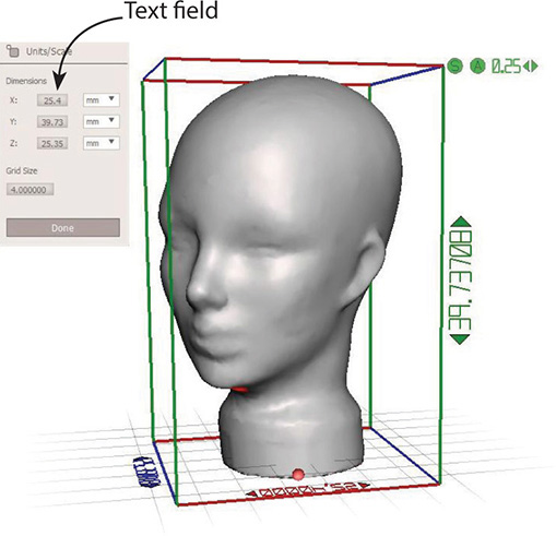
Figure 9-17 Set the models units. Change its size by typing in the text fields.
Measure/Dimension
Click this to measure features and distances between points (see Figure 9-18). Options are Type and Direction; a numeric distance appears after you click points.
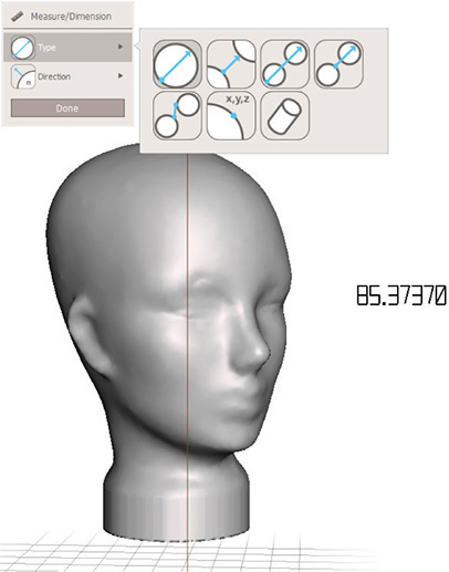
Figure 9-18 Measure distances between features.
Stability
Click this to check the surface area and volume of the model (see Figure 9-19). The ball shows the model’s center of mass. A green one means it’s stable and will stand up. A red one means it’s unstable. You can modify it somewhat by dragging the contact tolerance slider.
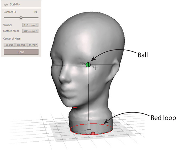
Figure 9-19 A stability check shows whether the model will stand up when printed. The ball is the center of gravity.
Strength
Click this to see if the model is strong enough to be printed (see Figure 9-20). Solid green means it is; red areas indicate weakness. Click the Show Sections box to see more defined areas of weakness. The head is completely green, so we can click Done.
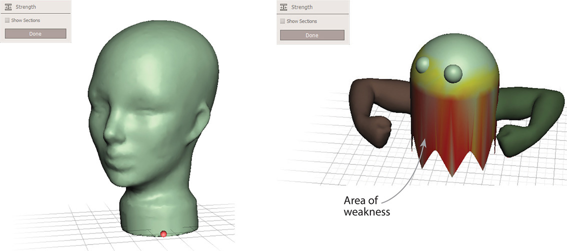
Figure 9-20 A completely green model means it’s strong enough to be printed. Red areas indicate weakness.
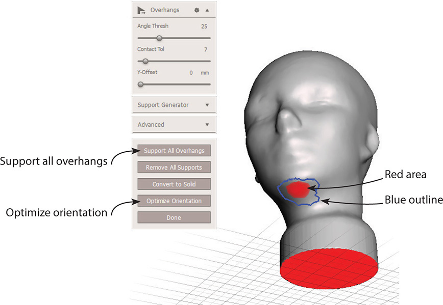
Figure 9-21 Red areas and blue lines show areas that need support and other overhangs.
Overhangs
Click this to see overhangs that will need support during printing. They’ll appear as red areas. Features that may or may not need support or may benefit from discretionary support will be outlined in blue.
Click the Optimize Orientation button at the bottom. The model will position to require the least amount of support. Then click Support All Overhangs to generate default overhangs. These are not joined to the digital model; they are separate components.
Notice all the options in the dialog box (see Figure 9-22). To adjust them, move the sliders or click on the numbers to bring up a text field. Press the TAB key to move between fields. Changing these options changes the overhangs. You may want to increase or decrease the default overhangs, thicken them, change the angle, and so on. Add and customize supports by clicking existing ones and dragging them to specific places on the model. If the posts tend to snap to other posts when doing this, hold the SHIFT key down and drag with the left mouse button. Clicking the same spot on a support several times generates multiple supports arrayed around it (see Figure 9-23). Cross-link supports to adjacent ones, which increases stability and serves as backup to failing supports. Remove supports by clicking them while pressing the CTRL key. Reset the defaults by clicking the gear icon at the top of the menu panel and clicking Reset to Defaults.
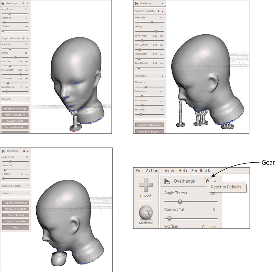
Figure 9-22 Generate and customize overhang support. Here you can see the results from different options. Click the gear to restore the defaults.
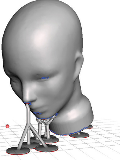
Figure 9-23 Click several times on a support to generate multiple supports arrayed around it.
Good supports are critical. If they break during the printing process, everything above them will fail. When in doubt, make them thicker, add more, or connect some together by dragging and clicking. Features that are angled less than 20° from the horizontal need the most support. Generally, 3mm is a sufficient support diameter, and they should only be slightly angled (for example, no less than 60° from the horizontal). Vertical 0.35mm supports every 1cm are typically enough to span an empty space below an overhang. If there are a lot of overhangs, the print may come out “fluffy” or droopy; consider breaking the digital model into parts for printing separately and then gluing or pinning the parts together.
Add supports after the model is scaled. If you rescale the model downstream, the supports may not scale correctly with it and end up too small to be effective or too large for easy removal. Know that many supports can be difficult to remove, especially on a delicate print. If the print breaks when you remove its supports, make a note of their settings so that you can readjust them next time. A lot of trial and error is involved in successful 3D printing.
TIP Be aware that the Optimize Orientation feature may return different results based on how the model is already oriented in Meshmixer. Try to optimally orient the model manually before applying this feature. For example, if there are features that wouldn’t need support if the model’s underside was flat on the build platform, then manually orient it that way instead of placing the model on its side (see Figure 9-24). The size of the build platform will also affect Optimize Orientation results.
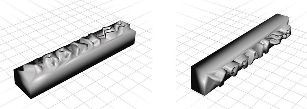
Figure 9-24 Investigate how different manual orientations affect the results of the Optimize Orientation feature. The orientation on the left won’t generate supports, but the one on the right will.
Finally, note the Convert to Solid option. It combines multiple models together into one 3D-printable model and lets you offset distance and adjust resolution.
Slicing
This tool identifies areas that have been sliced too thin or small for the printer (see Figure 9-25). Yellow areas are too small and orange ones are too thin. Adjust them with the options box.
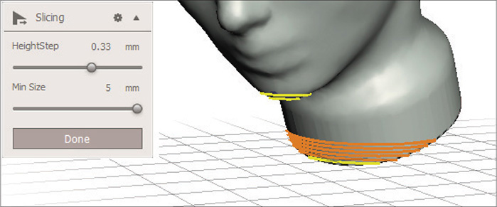
Figure 9-25 The Slicing tool identifies thin areas.
After analysis, save the file by clicking File | Save in the top menu bar (see Figure 9-26). Would you like to export it into a different file format? Click File | Export or the Export icon at the bottom of the menu panel and choose between .obj, .stl, .dae, .ply, .amf and .vrml. The .dae file type is Collada, an exchange format that imports into other software programs. Otherwise, click the Print icon to send the file to the Meshmixer print area.
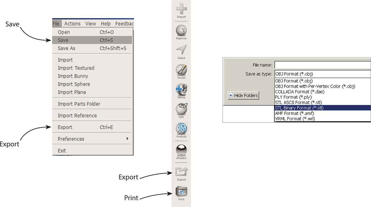
Figure 9-26 Save the file after analyzing it. Alternatively, click Export to turn it into an .obj, .stl, .dae, .ply, or .amf format. The .stl icon may look like the icon of an installed 123D app or of the MakerBot desktop icon.
The Meshmixer Print Area Interface
Clicking the Print icon brings the model and its supports to a new interface that has a menu bar at the top, a vertical menu panel, and a facsimile of the printer (see Figure 9-27). In the top graphic, the model is inside a MakerBot Mini and in the bottom graphic, the model is inside a Replicator 2. Different optimal positions and supports were also generated due to their different manual orientations in Meshmixer. Know that a model doesn’t have to be centered on the build plate. It will print just as well anywhere on the plate. You might want to print in different locations to make any painter’s tape you apply last longer.
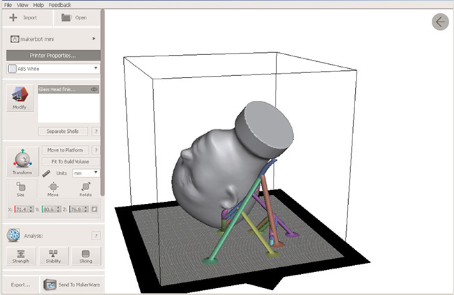
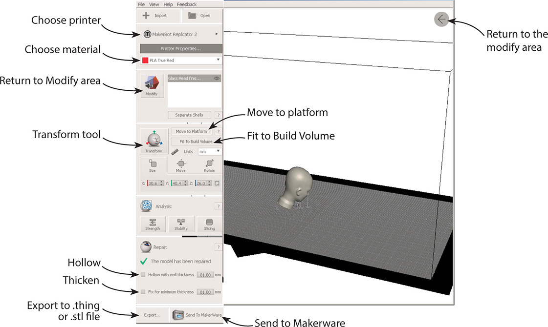
Figure 9-27 The model inside Meshmixer’s Print area. At top it’s in a facsimile of a MakerBot Mini; at bottom it’s in a MakerBot Replicator 2
To adjust for your machine, find Add | Edit Printers at the top of the vertical menu panel, click the drop-down arrow, and select yours (see Figure 9-28). If your printer isn’t there, click Choose Printers at the bottom of that window. Another window will appear. Click on the Add New Printer button at the bottom of that window and type the printer’s name.
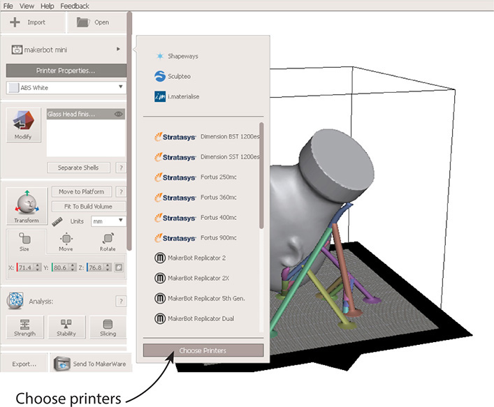
Figure 9-28 Scroll through the choices at Add | Printers to find yours. If it’s not listed, click Choose Printers and add it there.
Going down the menu panel, select the printer properties (parameters and filament). Click the next field to apply color to the model, if you want. The Separate Shells option breaks the mesh into different components for models printed with multiple materials. Click Move to Platform to ensure the model sits on the build plate. A model can be printed without being moved to the plate, but the Send to Printer process will take much, much longer. Fit To Build Volume fills the printer facsimile with the model.
Meshmixer’s Transform tool, shown in Figure 9-29, is accessed by clicking its icon or pressing T. It scales, moves, and rotates the model, discussed in detail in Chapter 6. However, once you do that, the supports disappear. If you clicked Fit To Build Volume, you saw that the supports disappeared, too. We’ll discuss how to handle that shortly. Clicking the Modify icon or the arrow in the screen’s upper-right corner returns you to Meshmixer’s Modify area. Changes made in the Print area are lost when the file is returned to the Modify area.
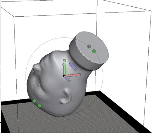
Figure 9-29 The Transform tool scales, moves, and rotates the model.
At the bottom of the menu panel are three features:
![]() Repair: The Model Has Been Repaired This is an automatic feature, not one you control. Upon import, Meshmixer analyzed every triangle and vertex in the model for problems and fixed them. A green checkmark means the repairs were successful.
Repair: The Model Has Been Repaired This is an automatic feature, not one you control. Upon import, Meshmixer analyzed every triangle and vertex in the model for problems and fixed them. A green checkmark means the repairs were successful.
![]() Hollow With Wall Thickness This hollows out a solid model, which reduces the amount of filament used (and the cost and time to print it). Basically, it sets the infill. Type the wall thickness desired in the text field and click anywhere on the screen for it to take effect. Click Preview to see a transparent view of the hollowed-out model (see Figure 9-30).
Hollow With Wall Thickness This hollows out a solid model, which reduces the amount of filament used (and the cost and time to print it). Basically, it sets the infill. Type the wall thickness desired in the text field and click anywhere on the screen for it to take effect. Click Preview to see a transparent view of the hollowed-out model (see Figure 9-30).
![]() Thicken Thin Parts By This is adaptive thickening. Meshmixer slightly widens parts of the model that are too small to print on your machine. This should only be used on models with small, pointy features such as claws, teeth, and hair. Type in a number and click somewhere on the screen for it to take effect.
Thicken Thin Parts By This is adaptive thickening. Meshmixer slightly widens parts of the model that are too small to print on your machine. This should only be used on models with small, pointy features such as claws, teeth, and hair. Type in a number and click somewhere on the screen for it to take effect.
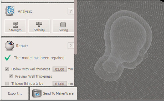
Figure 9-30 Hollow a solid model and set the wall thickness.
Regenerate the Lost Supports
As with the Transform tool, hollowing or thickening the model makes the supports disappear. Click Add Support Structure at the bottom of the vertical menu panel (see Figure 9-31). If you don’t see it, expand the window to fill the whole computer screen. It has the same tools for generating supports. However, if you have trouble zooming in enough to manually finesse them, go to File | Save Scene As, as shown in Figure 9-32, rename, and close the file. Reopen it in Meshmixer’s Modify area. Sliding the transparency shader over it verifies that the hollowing was indeed saved (see Figure 9-33). Generate the supports again. Notice how they now go to the top of the model (see Figure 9-34).
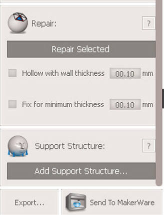
Figure 9-31 Click Add Support Structure to generate supports. If you don’t see this option, expand the window to fill the whole computer screen.
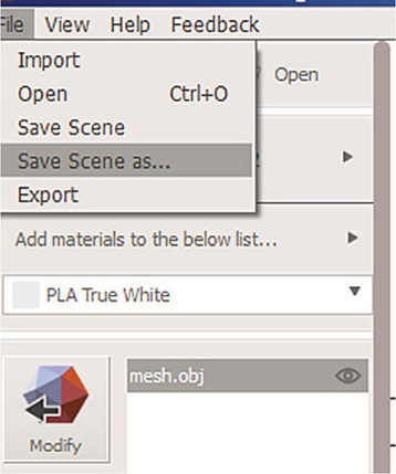
Figure 9-32 Click Save Scene As for a new .mix file that preserves changes made in the Print area.
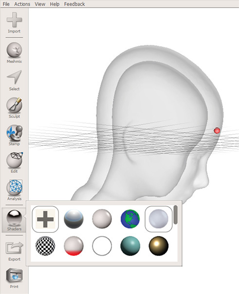
Figure 9-33 The transparency shader verifies that the model is hollow.
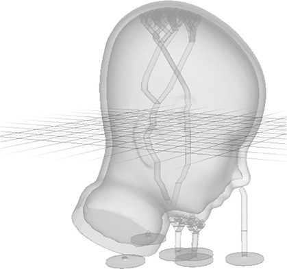
Figure 9-34 Regenerate the supports. This time they’ll go to the top of the model.
Export the File as a THING
Click Print to return to Meshmixer’s Print area. At the bottom of the vertical menu panel is an Export button. Click it for options to export the file in .stl or .thing format (see Figure 9-35). A .thing file is the MakerBot proprietary format. You can import it back into MakerBot Desktop later and continue to edit it. Despite the name, a .thing file is neither uploaded to nor downloaded from the Thingiverse. STL files are the dominant format there.
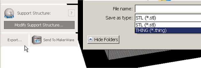
Figure 9-35 Click the Export button for options to export the file as an .stl or .thing.
Now click the Send to Makerware button. It’s at the bottom of the vertical menu panel, next to the Export button. The file will open inside MakerBot Desktop software (see Figure 9-36). Here, you can print it directly from the computer, export and copy it to a memory card, or tweak it some more.
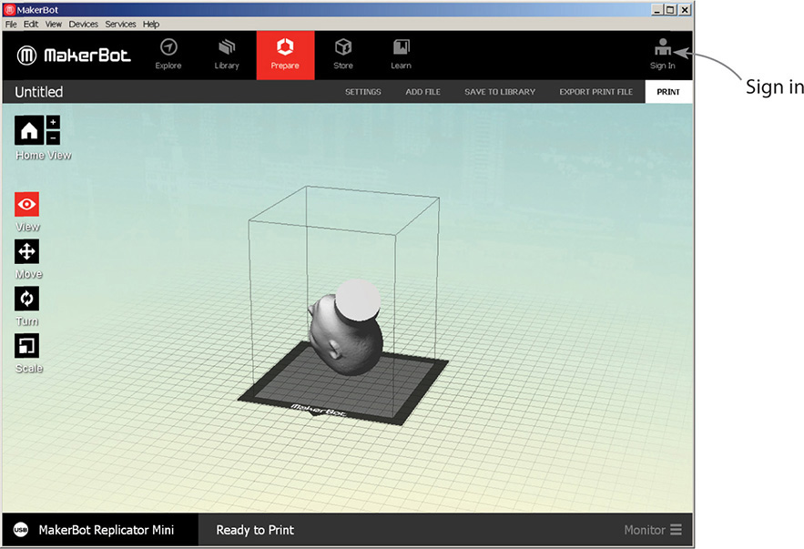
Figure 9-36 Click Send to Makerware to open the file inside MakerBot Desktop.
The MakerBot Desktop Interface

In the upper-right corner is a sign-in icon. Use your Thingiverse log-in information. You don’t have to be logged in to print, but a dialog box asking you to log in will appear and must be closed before you can proceed. Sometimes this dialog box hides; you may find it behind the Meshmixer window. You can also close out of Meshmixer once you send the model to MakerBot Desktop.
The model will appear on the build plate in the MakerBot Desktop interface. Along the left side are five buttons: Home View, View, Move, Turn, and Scale. Click each to access their options (see Figure 9-37):
![]() Home View Returns you to the default view. Click the plus and minus buttons to zoom in and out.
Home View Returns you to the default view. Click the plus and minus buttons to zoom in and out.
![]() Look Lets you view the model orthographically instead of the default perspective.
Look Lets you view the model orthographically instead of the default perspective.
![]() Move Change the model’s position.
Move Change the model’s position.
![]() Turn Change the model’s rotation.
Turn Change the model’s rotation.
![]() Scale Change the model’s dimensions.
Scale Change the model’s dimensions.
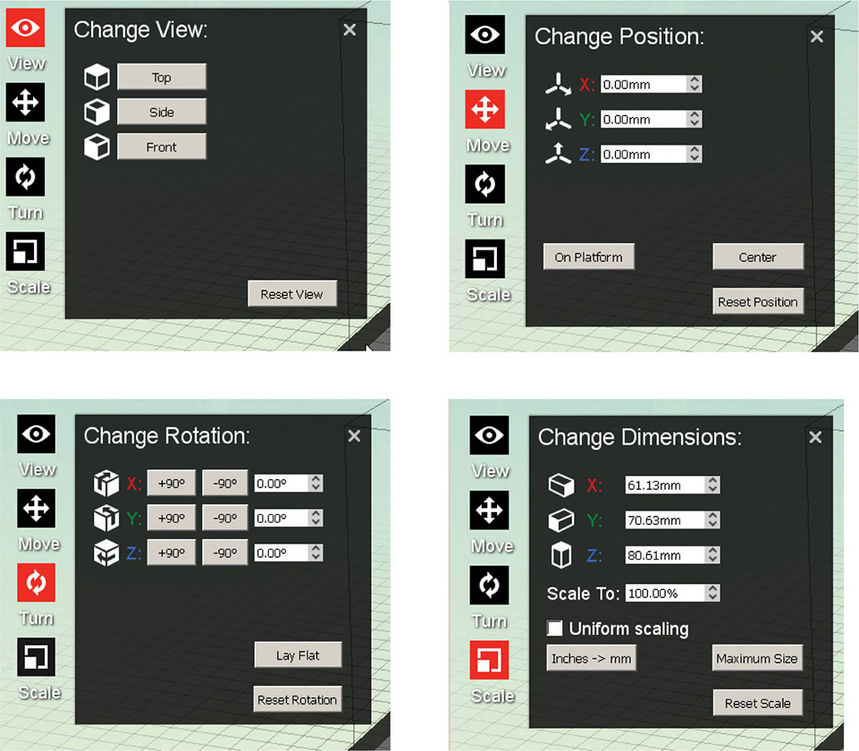
Figure 9-37 Options for changing the model’s view, position, rotation, and scale.
As mentioned earlier, changing the scale may mess up the supports. But if the model imports backwards, sideways, or upside down, you can fix that with no adverse effects. If you want two heads, click the model. A gold outline indicates that it’s selected. Then press CTRL-C and CTRL-V to make a copy, supports and all (see Figure 9-38).
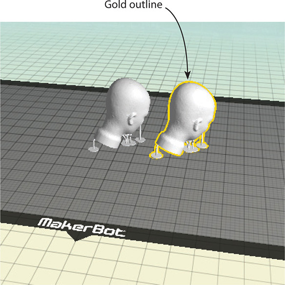
Figure 9-38 Copy the model by selecting it and pressing CTRL-C and CTRL-V.
At the top of the screen are five icons:
![]() Explore takes you to the Thingiverse.
Explore takes you to the Thingiverse.
![]() Library helps set up the printer.
Library helps set up the printer.
![]() Prepare lets you tweak the model before printing.
Prepare lets you tweak the model before printing.
![]() Store takes you to curated digital models for sale.
Store takes you to curated digital models for sale.
![]() Learn has tutorials.
Learn has tutorials.
If you get a “You need an internet connection” message after clicking on an icon, click the Retry button and it should find your internet connection.
When Prepare is clicked, a menu bar appears below the five icons. Here, you can choose the physical model’s settings, add another file, and save the file to an online library (you need to be logged in for this). Export Print File does just that; it exports a file that can be copied onto an SD card and inserted into the MakerBot for direct printing (see Figure 9-39). The Mini is the only model without a card slot. When the export is finished, a window will appear showing how much time and filament the print will take.
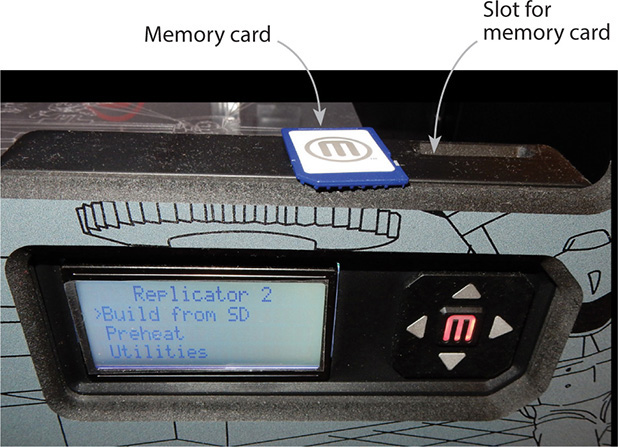
Figure 9-39 An exported file can be copied to a memory card and inserted into the MakerBot for direct printing. Here, a card is next to the slot on a fourth-generation Replicator 2. Press the left arrow to scroll to the file, and then press the M button to start printing.
At the top of the screen are the File, Edit, View, Devices, Services, and Help menus. You can also set preferences and view the model orthographically. File | Examples contains premade models to print. Fifth generation machines require clicking on Devices | Change Filament each time you start a print (see Figure 9-40). The submenu has a Load Filament option that will instruct you when to physically push the filament into the guide tube. If you skip this step, the extruder will go through the motions but not deposit any filament.
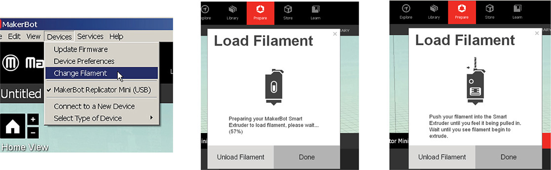
Figure 9-40 On fifth generation MakerBots, click Devices | Change Filament to load the filament each time you start a print.
At the screen’s bottom-right, click on Monitor to access buttons that let you cancel, pause, and change the filament spool (see Figure 9-41). Pausing is useful for changing filament colors and almost-empty spools. Fifth generation machines pause automatically when detecting an empty spool, but earlier machines don’t.
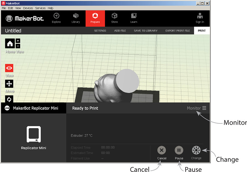
Figure 9-41 Click on Monitor at the screen’s bottom-right to access buttons that let you cancel, pause and change the filament spool.
You can also pause a MakerBot directly by pressing its Action button. On a Mini this button is on the lower-right front face. Press once and it will turn from red to blue. Press again to restart. Press and hold to cancel the print. On a fourth generation Replicator 2, the Action button is the red M. Press its left arrow, select the pause option, and press the button again to resume printing.
The Settings Menu
Click the Settings menu to choose the physical model’s properties (see Figure 9-42). The resolution options are low (fast), standard, and high (slow). Models with thin supports should be done at a slow speed; models with thick supports can be printed faster. Ensure that Raft and Supports are checked if you generated them. Even if there are no supports, you might want to build a raft anyhow to help the base of a long, thin, wide model adhere better to the build plate (their corners tend to curl up when cooling). Under Advanced settings, accept the slicer defaults or type your own. You can also make and save a profile with custom settings for future prints.
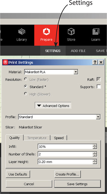
Figure 9-42 Click the Settings menu to access the Print Settings. Here you choose the physical model’s properties.
Preview and Print from the Computer
Click the Print button to print from the computer. It won’t start printing right away. Rather, a file will be generated and sent to it; you’ll see a status bar. If the file takes a long time to send (“long time” being based on its size, but generally should take less than half an hour), check that the print is on the build platform. Recall that not being on the build platform will greatly slow down this process.
After the print has been generated, a window will appear that shows the time and filament required, print and cancel options, and a Preview Print link (see Figure 9-43). Click that link to see the toolpath (see Figure 9-44). On the left is a slider you can drag to see what the print will look like at each layer (see Figure 9-45).
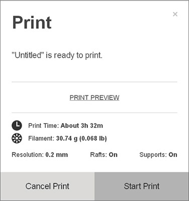
Figure 9-43 This window appears after the file is sent to the printer. It shows the time and filament required, has Print and Cancel buttons, and a Preview Print link.
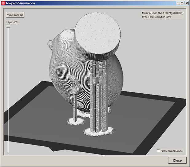
Figure 9-44 Click the Preview Print link to see the tool path.
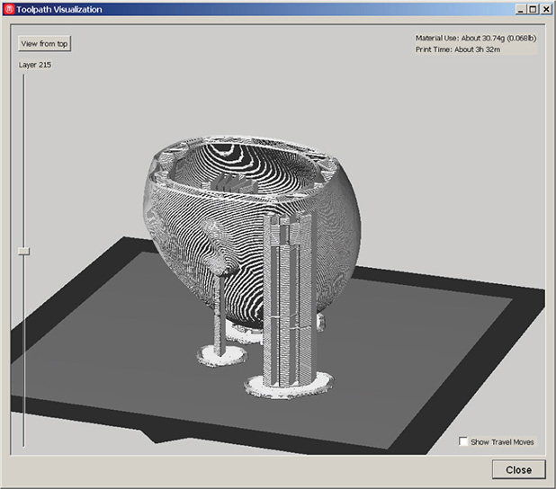
Figure 9-45 Drag the slider to see the print at each layer.
Then click Start Print to begin printing. On the printer itself, a blinking light means the printer is warming up or waiting for user input and a solid light means the printer is working.
Finally: Ta da! The physical print (see Figure 9-46).
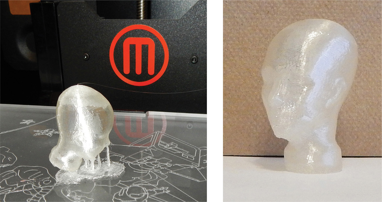
Figure 9-46 On the left the print is still on the build platform with its supports and raft. On the right, the supports have been removed and the print is standing upright.
Finding Help
A lot can go wrong during the printing process: The software doesn’t connect to the printer. The extruder clogs, the printer overheats, or the build plate isn’t level. Periodically check on a print that takes hours to complete to make sure all is going well. At https://www.makerbot.com/support/new/Desktop/01_MakerBot_Desktop_Knowledge_Base is a knowledge base. User forums are listed at the end of this chapter. Those who have a Makercare contract, or whose machines are still under warranty, can open a support ticket at https://www.makerbot.com/support or email [email protected].
Printing with a Service Bureau
Service bureaus are third party companies that offer online 3D printing services. They charge by material and volume. You upload your model through Meshmixer, your 123D account, or directly. You choose a material and are quoted a price. Then you enter your address and payment information. A couple of weeks later the model will arrive in the mail. Popular service bureaus are Shapeways, Sculpteo, Ponoko, and i.materialise.
Service bureaus print on expensive, commercial-grade machines, hence their prints are much higher quality than what a home printer produces. They also offer more material choices and accept more file formats. For instance, you can see all the formats Sculpteo accepts at www.sculpteo.com/en/help/#accepted-formats.
To use a service bureau, turn your file into an .stl or other format the bureau accepts. Then in Meshmixer’s Print area, click the arrow in the Printer field and choose a service bureau (see Figure 9-47). The link takes you to its website. Upload your file, select a material, view the price, and check out (see Figure 9-48). The file will undergo a software analysis. If the model is not printable you’ll get an error message, although some bureaus may try to fix it. It will also undergo a manual review for content acceptability.
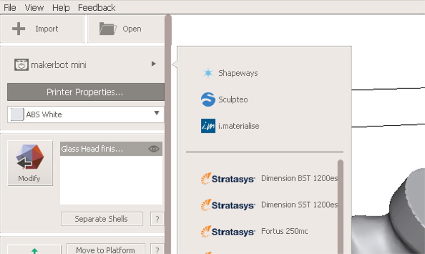
Figure 9-47 Choose a service bureau.
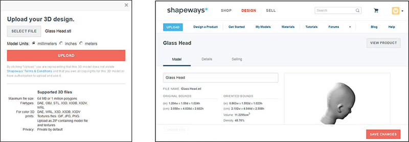
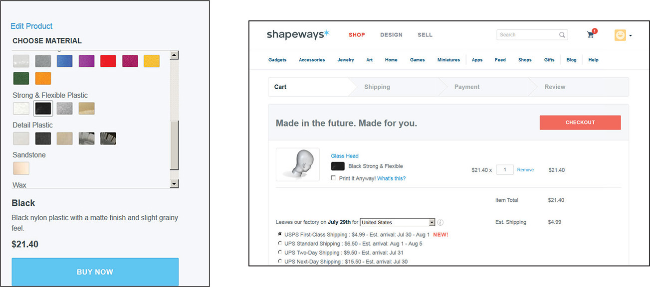
Figure 9-48 Ordering on the Shapeways website
You might want to visit each of the websites directly to compare features (the URLs appear at the end of this chapter). Another option is 3D Hubs, a network of local printers. They may offer a faster turnaround or let you pick the print up yourself. Some third parties may help tweak designs as well as print them. Not all remove the supports, though; ask if that’s important to you. MakerBot retail stores also have a printing service. Walk in with your .stl, .obj or .thing file on a thumbdrive.
Summary
In this chapter we discussed the 3D printing process, filament types, and what makes a model printable. We used Meshmixer to analyze a model for printability and generated supports for it. We hollowed the model out, sent it to MakerBot Desktop, set printing preferences, and then printed it on a MakerBot. We also discussed how to print through a service bureau.
Sites to Check Out
![]() Video showing how to level a build plate www.youtube.com/watch?v=LzgcFGbMxMU
Video showing how to level a build plate www.youtube.com/watch?v=LzgcFGbMxMU
![]() MakerBot operators forum https://groups.google.com/forum/#!forum/makerbot
MakerBot operators forum https://groups.google.com/forum/#!forum/makerbot
![]() Official Meshmixer forum http://meshmixer.com/forum/
Official Meshmixer forum http://meshmixer.com/forum/
![]() Network of local printers www.3dhubs.com
Network of local printers www.3dhubs.com
![]() Shapeways printing tutorials www.shapeways.com/tutorials?li=nav
Shapeways printing tutorials www.shapeways.com/tutorials?li=nav
![]() Sculpteo FAQ www.sculpteo.com/en/help/
Sculpteo FAQ www.sculpteo.com/en/help/
![]() Makerbot Printshop www.makerbot.com/printshop. This is a tablet app for downloading and printing curated models from Makerbot’s digital store.
Makerbot Printshop www.makerbot.com/printshop. This is a tablet app for downloading and printing curated models from Makerbot’s digital store.
![]() Download the Autodesk Print utility www.apps.123dapp.com/3dprint/install.html. This app prepares files for printing, which is useful if you don’t use the 123D apps or don’t need Meshmixer’s modifying abilities.
Download the Autodesk Print utility www.apps.123dapp.com/3dprint/install.html. This app prepares files for printing, which is useful if you don’t use the 123D apps or don’t need Meshmixer’s modifying abilities.
![]() Four service bureaus websites www.shapeways.com, www.sculpteo.com/en/, www.ponoko.com, and www.i.materialise.com
Four service bureaus websites www.shapeways.com, www.sculpteo.com/en/, www.ponoko.com, and www.i.materialise.com
![]() Website showing prints gone bad http://epic3dprintingfail.tumblr.com/
Website showing prints gone bad http://epic3dprintingfail.tumblr.com/
![]() Website that opens and converts different file types into .stl http://meshlab.sourceforge.net/
Website that opens and converts different file types into .stl http://meshlab.sourceforge.net/
![]() Website that edits, analyzes, scales, measures, and repairs .stl files http://cloud.netfabb.com/
Website that edits, analyzes, scales, measures, and repairs .stl files http://cloud.netfabb.com/
![]() Website with wall thickness suggestions for different materials and detail levels http://www.shapeways.com/materials/material-options
Website with wall thickness suggestions for different materials and detail levels http://www.shapeways.com/materials/material-options