Chapter 14
HD 3DTV and Autostereoscopy
The ultimate display would, of course, be a room within which the computer can control the existence of matter.
Ivan SUTHERLAND, 1965
14.1. Introduction
The difference between 3D and 2D displays is not always clearly defined, in spite of the seemingly clear 2D/3D dichotomy. With the notable exception of volumetric devices, most of the so-called 3D displays currently available are, in fact, simple 2D displays. The images projected onto these displays may be assimilated to 2D surfaces, using psychovisual cues to create an illusion of depth and increase its perception. With these limitations in mind, we may define 3D displays as devices able to reproduce dynamic depth signals on the basis of psychological (motion parallax and kinetic depth) and/or physiological cues (stereoscopy, accommodation and convergence).
A broad range of technologies currently allow 3D display [HOL 11, LUE 11, MAT 04]. In this chapter, we will only consider those based on apparent depth with the objective of separating information destined for the right and left eyes using the same surface (the screen). The methods used to guide optical beams exiting the screen have permitted the development of a number of different 3D display models, which are generally classified as stereoscopic or autostereoscopic.
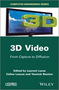
A classification of these methods is shown in Figure 14.1. The proposed taxonomy consists of arranging these methods so that the number of views transmitted by each type of display increases from left to right, from 2-view stereoscopic displays to multiview horizontal parallax displays and multiview volumetric displays. These systems fall into the following categories:
– Helmet-mounted displays (HMDs): often used in virtual reality, these devices allow distinct images to be sent to the user, one for each eye. The principle involved is similar to that used in head-up displays, but with a separate miniature screen for each eye, often integrated into a helmet.
– Stereoscopic displays: these devices require users to wear glasses that filter incident light into separate image signals for the right and left eyes.
– Autostereoscopic displays: unlike the previous categories, these devices do not require the user to wear glasses. An optical technique applied to the screen directs the light so that each view n (where n ≥ 2) is correctly transmitted to different observers.
– Holographic displays: this last category is based on technology, still confidential, able to recreate virtual holographic images [LUC 95], mostly static for the moment. This category is essentially composed of prototypes designed around specific optical elements with the ability to dynamize a hologram1. Other systems using similar principles exist, under the name of holoscopy [BOG 89]; these often include full-parallax (or integral imaging) autostereoscopic displays.
Figure 14.1. Taxonomy of 3D displays (see [HOL 11] for further details)
All, or almost all, of these technologies are already in use in a number of domains of application, both in the civilian and military sectors, in academia and in industry, in connection with virtual reality [KOO 07] (see Chapter 15), biomedical imaging (see Chapter 20) or multimedia creation [SMO 11] and many other applications.
We will begin by discussing the subjacent technological elements involved in these techniques, before describing the principles of multiplexing multiview images, including filter design and use. We will conclude the chapter by considering the generation of multiview images and offering perspectives for further research.
14.2. Technological principles
The projection of 3D images, created using stereoscopic techniques, involves a number of processes to allow these images to be displayed on a flat surface. In this section, we will present the technological principles used to recreate the sensation of depth, which, we should remember, is simply an illusion.
14.2.1. Stereoscopic systems using glasses
Four types of projection are generally used:
– Alternating: these “active” devices display left and right views, in turn, on the screen (or projector). The impression of 3D is recreated via goggles using liquid crystals, and each pair must be perfectly synchronized with an image emitter. The emitter alternately obscures one of the two lenses (frequencies of ≥60 Hz per eye to avoid a “shimmer” effect) so that only the other eye receives the corresponding image. The retinal persistence effect allows the brain to recreate an illusion of depth by temporal mixing of the stereo pairs.
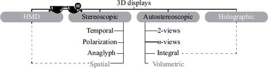
– Polarizing: these systems exploit the orientation property of light. This is known as polarization (see Figure 14.2). Screens using this principle are mainly based on linear polarization, which gives the best optical performance. However, systems using projection onto a metallic screen, as in cinemas, use circular polarization that allows spectators to sit in a wider variety of locations. In all the cases, the filters used effectively sieve the light, leading to a loss in resolution.
– Anaglyph: these systems use complementary color filters (different wavelengths) to transpose images forming a stereo pair. They do not generally allow correct recreation of the colors of images, but are simple to use and cheap to produce.
– Simultaneous: in this case, the collocation of left and right images is not guaranteed. These systems, similar to Wheatstone and Brewster’s stereoscopes (see Chapter 1), are generally used in HMDs, the modern equivalent of the stereoscopes mentioned above.
Figure 14.2. Light polarization principle
14.2.2. Autostereoscopic displays
Unlike the systems described above, autostereoscopic devices [DOD 05, HAL 05] do not require users to wear optical equipment. Angular view separation, notably in the case of displays, is carried out by an optical element, the operation and properties of which are discussed in detail below. We may distinguish four types of systems:
– 2-views: these displays simultaneously show two views (one for each eye). The position of the user is essential for correct relief perception. Certain models include an optical tracking mechanism that allows free movement of the head while controlling image distortion2.
– n-views: these displays extend the horizontal field of vision by simultaneously recreating more than two views (generally between five and nine at the time of writing). This gives a wide range of preferential positions from which the spectator may observe different stereo pairs. Moreover, this technology enables collaborative 3D vision, allowing several individuals to observe the same scene simultaneously from slightly different angles.
– Integral imagery: the optical elements in this equipment allow a double angular separation of views, vertically as well as horizontally. Devices using this technology thus offer a visual experience close to real life, as a scene may be observed from several angles (around, above and below) [MAR 09]. These systems reproduce a 4D light field (plenoptic function [GOR 96, LEV 96]), creating double parallax stereoscopic images when the observer moves.
– Volumetric: unlike the three previous system types (where the optical image exists in the plane of the screen), these systems [JON 07, STA 10] produce a genuine 3D display by generating images at different positions in space. Different techniques are used to do this, such as the use of a rotating projection display to produce a spherical image volume [FAV 05] or the use of variable focus lenses to position several “slices” at different optical depths (see Figure 14.8).
14.2.3. Optical elements
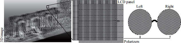
In recent years, a number of university and industrial laboratories have developed autostereoscopic 3D displays. While certain attempts remain at an experimental stage, others have resulted in genuine commercial products. Most of these devices currently use conventional liquid crystal display (LCD) tiles, with the addition of an optical element that serves to redirect the incoming image (combination of lower resolution images) (see section 14.4) in priority viewing directions (see Figures 14.3 and 14.5). The number of views that these screens can handle and their angular separation (parallax) also characterize critical factors which designers, content producers and users must take into account, as they affect the whole chain of production of 3D images, from capture to diffusion. These optical elements, seen as an extension of work by Lippmann, who established the foundations of integral photography at the start of the 20th Century, are based on the use of parallax barriers or lens filters (see Figure 14.4). Several variants of these filters are currently used: strip barriers or lenticular sheets for horizontal parallax systems, and pinhole barriers or micro-lenses for full-parallax systems. Diffraction optics may also vary depending on the system (linear or circular) and may be mixed over several layers. Other solutions use colored barriers that allow selective filtering based on the wavelengths emitted by the LCD tile. These technologies have enabled the creation of a number of different display models, the main characteristics of which are shown in Table 14.1.
Figure 14.3. Operating principle of a parallax barrier
14.2.4. Measurement of autostereoscopic display
The accurate quality of perceived depth is an essential element in the use and practice of autostereoscopic techniques. Several factors are involved, in addition to physiological aspects concerning the observer (see Chapter 4). These include:
– The reproduction device itself. The autostereoscopic displays currently available are characterized by (1) the number of viewpoints they reproduce (n ![]() (5, 7, 8, 9) for the most common devices), (2) the resolution (generally a full high-definition LCD tile), (3) the distance range offering high-quality 3D restitution and (4) the optical equipment ensuring angular separation of the n views.
(5, 7, 8, 9) for the most common devices), (2) the resolution (generally a full high-definition LCD tile), (3) the distance range offering high-quality 3D restitution and (4) the optical equipment ensuring angular separation of the n views.
– The nature of the displayed media, i.e. the conditions (real or virtual) in which the images were created. Chapter 4 gives an overview of this issue.
Figure 14.4. Optical filters
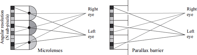
Table 14.1. Main characteristics of autostereoscopic 3D displays
| Parallax barrier | Lenticular | |
|---|---|---|
2D/3D commutation Portrait/landscape orientation View separation Undesirable effects (3D cross-talk, moiré) Screen luminosity 2-view display |
|
|
Figure 14.5. Observation windows produced by different optical beams. The optimal comfort zones for good 3D vision (stereopsy) correspond to zones 1–6
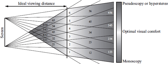
That said, the user may move laterally, advance or reverse in relation to the display without leaving the zone of acceptability, a condition which ensures that the quality of stereoscopic visualization will be maintained. Figure 14.5 illustrates this principle for a 6-view 3D display. For each zone of the viewing space, it shows the image numbers visible from left to right. The optimal viewing distance corresponds to regions 1–6. If the observer is placed so that one of his/her eyes is in zone 1 and the other is in zone 2, he/she will receive the full stereoscopic effect on screen. However, if the observer moves to a position where his or her left eye is in zone 23 and the right eye is in zone 34, he or she will still receive a stereoscopic view of the content, but there may be perceptible visual discomfort in the transition zone of views 2, 3 and 4. This artifact is known as cross-talk, and produces ghosting effects; these effects may be attenuated using specific software and/or material resources as described in [CHU 11]. The color gradation zone in Figure 14.5 represents valid positions for both eyes for an observer, excluding the issue of cross-talk. Therefore, the user has lateral freedom of movement in front of the screen across a distance known as the lobe, defined by the relationship (n – 1) × b (where n is the number of views and b is the interocular distance), but also has the possibility of moving toward or away from the screen. This allows several individuals to simultaneously perceive 3D images using different stereoscopic pairs. If the same observer is located in front of the plane representing ideal viewing positions, he or she will be subject to a hyperstereo or pseudoscopy phenomenon. The latter phenomenon corresponds to a permutation of left and right views of a stereo pair that produces an inversed relief effect, giving a confusing image that is difficult to interpret.
14.3. Design of mixing filters
The matrix representation of a 2D digital image I associates each position (x, y) ![]() [0, M[×[0, N[ with an intensity c
[0, M[×[0, N[ with an intensity c ![]() [cmin, cmax]p (generally [0.255]3 in the case of color images). This arrangement facilitates not only access to and processing of data (the image is defined as a matrix of integer values), but also their display on an ordinary display device. If we then consider a volumetric device, a third parameter coding the depth of a (voxel) point needs to be added to the 2D coordinates. In the case of certain stereoscopic displays, access to this third dimension depends on another parameter: time. This clearly shows the interdependence of these dimensions (3D + time), in particular when it comes to properly addressing a 3D multiview visualization device in a unified manner (n ≥ 2). Grasnick [GRA 10] and Ju-Seog et al. [JUS 04] discuss this issue, and we will use the first of these references as a basis for discussion of multiview image multiplexing in the following section. The multiplexing algorithm presented below allows us to produce arrangements of multiview images for different display devices, both real and virtual, volumetric and stereoscopic; we will illustrate the principle for, and using, autostereoscopic displays. While this algorithm is generic, it is not suitable for specifying all multiplexing schemas.
[cmin, cmax]p (generally [0.255]3 in the case of color images). This arrangement facilitates not only access to and processing of data (the image is defined as a matrix of integer values), but also their display on an ordinary display device. If we then consider a volumetric device, a third parameter coding the depth of a (voxel) point needs to be added to the 2D coordinates. In the case of certain stereoscopic displays, access to this third dimension depends on another parameter: time. This clearly shows the interdependence of these dimensions (3D + time), in particular when it comes to properly addressing a 3D multiview visualization device in a unified manner (n ≥ 2). Grasnick [GRA 10] and Ju-Seog et al. [JUS 04] discuss this issue, and we will use the first of these references as a basis for discussion of multiview image multiplexing in the following section. The multiplexing algorithm presented below allows us to produce arrangements of multiview images for different display devices, both real and virtual, volumetric and stereoscopic; we will illustrate the principle for, and using, autostereoscopic displays. While this algorithm is generic, it is not suitable for specifying all multiplexing schemas.
For a sub-pixel i = f(x), the identification of a view V in a sequence of images (n) in the case of a one-dimensional display may be simply defined by the relationship V = i mod n. Taking n = 3 and i ![]() [0.5], we obtain the interleaving sequence (0, 1, 2, 0, 1, 2), which corresponds to the mixing of the three reference views. In 2D, this extended relationship is shown as follows:
[0.5], we obtain the interleaving sequence (0, 1, 2, 0, 1, 2), which corresponds to the mixing of the three reference views. In 2D, this extended relationship is shown as follows:
where ![]() and
and ![]() correspond to repetition factors and
correspond to repetition factors and ![]() and
and ![]() represent position modulation parameters. The matrix form
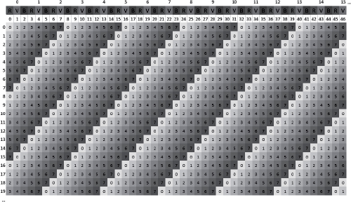
represent position modulation parameters. The matrix form ![]() of this relationship then allows us, specifying the number of views and the different parameters mentioned above, to determine the masks to use in order to mix different views before display. Examples of the use of this algorithm will be given below. In Figure 14.7, we see that view interleaving is carried out not using successive pixels in the LCD screen, but directly in the red, green and blue (RGB) channels. The notion of position must therefore be clearly assimilated to one of the sub-pixels (see Figure 14.6).
of this relationship then allows us, specifying the number of views and the different parameters mentioned above, to determine the masks to use in order to mix different views before display. Examples of the use of this algorithm will be given below. In Figure 14.7, we see that view interleaving is carried out not using successive pixels in the LCD screen, but directly in the red, green and blue (RGB) channels. The notion of position must therefore be clearly assimilated to one of the sub-pixels (see Figure 14.6).
Figure 14.6. Multiview representation of a pixel (nine views)

Figure 14.7. Mixing filters for 4D-view screens with eight views (i ![]() [0.46], j
[0.46], j ![]() [0.19], n = 8, qa = 1, qb = 1, qx = 1, qy = 1)
[0.19], n = 8, qa = 1, qb = 1, qx = 1, qy = 1)
The generalization of equation [14.1] is presented in a very similar manner, as shown by the following relationship:
knowing that for n = 2, we return to:
This equation is also suitable for displays using several layers of liquid crystals, such as the DepthCube3, with z = n = 20, or the Perspecta [FAV 02], where z = n = 198 with a value of z expressed as an angle.
Figure 14.8. DepthCube and Perspecta volumetric screens, Actuatily Systems Inc. [FAV 02]
14.4. View generation and interleaving
14.4.1. Virtual view generation
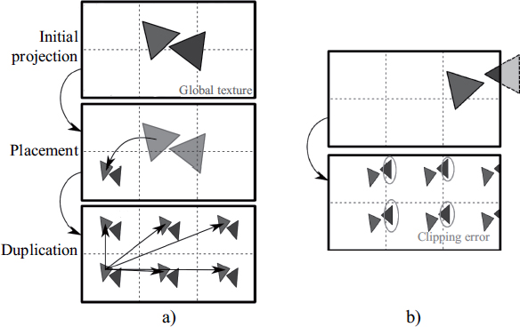
When autostereoscopic devices are coupled with a 3D rendering engine rather than multiple video flows, it becomes necessary to request n synthesized images. As the value of n may be high (5, 7, 8, 9 etc.), it becomes difficult to render these images within a reasonable interaction time (≥30 Hz), and this may have detrimental effects on image quality. However, during the rendering of these n-views, a variety of information is shared, not only including geometric information (positions, normals of synthesized objects, etc.) but also radiometric information (diffuse color, texture, etc.). While proprietary techniques (Nvidia [DEV 06]) exist for stereoscopy, they are poorly suited to autostereoscopy and do not solve the issue of rendering time. Certain optimizations have been developed for specific rendering algorithms: ray tracing [ADE 93] and point splatting or volumetric rendering [HUB 06, HUB 07]. We will concentrate on approaches that improve rendering time by rasterization, the technique most commonly used for rendering synthesized images. One approach that aims to optimize the rendering time of n-views of the same scene, illustrated in Figure 14.9, exploits geometry shaders4 in order to automatically duplicate each triangle as many times as there are views. Each of these triangles must then be sent to a buffer associated with each camera before final composition (see section 14.4.2).
Figure 14.9. Overview of our multiview stereoscopic GPU rendering method
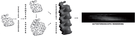
During the first stage, the graphics pipeline duplicates the 3D scene for each view; there is therefore no need to transfer data to the pipeline more than once, a transfer which can be very costly for bulky scenes. In the vertex shader stage, there is no need for projection into the camera space, as this will be carried out by the geometry shader for each rendered view. The vertex shader is responsible for all calculations relating to mesh vertices, which are carried out only once (diffuse color, calculation of normals, texture coordinates, etc.). The bulk of the work is then carried out by the geometry shader, where each primitive is duplicated and projected onto each viewpoint (see algorithm 14.1). The geometry shader has the capacity to duplicate each primitive (triangle) and to position it as desired. The final stage involves explicit generation of views, for which two possibilities exits: either the n views are stored as n distinct images (or buffers) or they are directly generated into a vast texture made up of the n viewpoints.
The first technique requires the use of frame buffer objects, which are simply rendering buffers, associated with the multiple render target technique, which allows all of these buffers to be filled in a single step. This technique, however, has significant limitations relating to the depth buffer, which is shared by all views, generating undesirable artifacts on the edges of objects.
The second technique consists of correctly positioning each primitive in each subpart of the image corresponding to the view indicated by the primitive (see Figure 14.10). In this case, we need to be attentive to clipping problems between each sub-image; this problem may be solved using explicit clipping in the geometry shader (see [DE 10]5). The simplest solution, however, is to use the viewport array extension in OpenGL6, shown in algorithm 14.1, where each generated primitive is sent to a specific viewport, thus managing clipping implicitly.
Algorithm 14.1. Example of a geometry shader for geometry cloning using an extension of viewport arrays

14.4.2. View interleaving
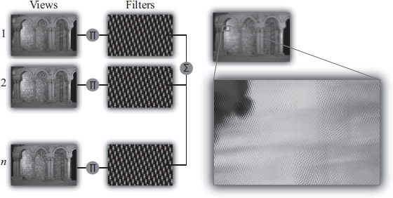
Once the n views have been generated, an image acceptable to the autostereoscopic device must be produced. To do this, we have n views, which are either stored in separate textures or combined in the same texture. Each view passes through a filter, which distributes pixels in the final image in a way suitable for the autostereoscopic device (see section 14.3). To render the final image in graphic processing units (GPU), a final rendering stage is necessary, where a triangle is drawn to cover the whole of the image7. Interleaving must be carried out in the fragment shader, which fills each pixel of the final image using equation [14.1] and the n textures corresponding to the n views, as shown in Figure 14.11.
Figure 14.10. a) Use of a texture for multiview rendering; b) clipping issue for this technique
During the final stage, we may consider anti-aliasing, for which several techniques have been proposed [MOL 05, VET 07, ZWI 07]. However, we recommend morphological anti-aliasing type approaches (MLAA), such as [JIM 11], which operate in postprocessing, applied during this final stage.
14.5. Future developments
While it is currently possible to create our own 3D displays [HIR 10], several factors, such as the intrinsic resolution of the selected LCD tiles or, to a lesser extent, the exclusive consideration of horizontal disparity, limit the expansion of autostereoscopic techniques.
Figure 14.11. View interleaving principle with mixing filters
Several studies are currently underway in an attempt to limit these effects. First, studies based on current technology include work on characterizing 3D displays [LER 09]. These elements, with the addition of specific anti-aliasing strategies for autostereoscopy, improve the 3D rendering of existing content.
Another pathway for improving autostereoscopic use consists of considerably increasing display resolution, without necessarily increasing the number of views. The recent development of a new generation of 4K (ultra HD) screens is promising in this respect, and industrial actors have announced that 4K-based 3D solutions will be released in 2013.
Finally, other approaches propose holoscopic systems, allowing diffusion of integral imagery in the form of discretized plenoptic functions [FUC 08, LAN 10, WET 11] (lumigraphs [GOR 96] or lightfields [LEV 96]). These systems use multilayer 3D displays or pico-projectors [JUR 11].
14.6. Conclusion
A wide variety of devices currently allow 3D image display. While they mostly remain associated with specific domains of application, they clearly show a long-term trend toward the democratization of these technologies and a genuine, permanent spread of 3D content. In this context, this chapter has essentially been devoted to autostereoscopic techniques, which present a number of advantages along with certain limitations. More specifically, we discussed the way in which these systems operate and the approaches used, either using calculated images or real images, before presenting a number of recent developments providing considerable improvements in the quality of perceived images.
14.7. Bibliography
[ADE 93] ADELSON S.J., HODGES L.F., “Stereoscopic ray-tracing”, The Visual Computer, vol. 10, pp. 127–144, 1993.
[BOG 89] BOGUSZ A., “Holoscopy and holoscopic principles”, Journal of Optics, vol. 20, no. 6, pp. 281–284, 1989.
[CHU 11] CHULHEE L., GUIWON S., JONGHWA L., et al., “Auto-stereoscopic 3D displays with reduced crosstalk”, Optics Express, vol. 19, no. 24, pp. 24762–24774, 2011.
[DE 10] DE SORBIER F., NOZICK V., SAITO H., “GPU-based multi-view rendering”, Computer Games, Multimedia and Allied Technology (CGAT 2010), Singapore, pp. 7–13, April 2010.
[DEV 06] DEVELOPPER TEAM N., “Nvidia: GPU Programming Guide version 2.5.0 (GeForce 7 and earlier GPUs)”, electronic document, available at http://developer.nvidia.com/object/gpu_programming_guide.html, 2006.
[DOD 05] DODGSON N.A., “Autostereoscopic 3D displays”, Computer, vol. 38, no. 8, pp. 31–36, 2005.
[FAV 02] FAVALORA G.E., NAPOLI J., HALL D.M., et al., “100-million-voxel volumetric display”, Proceedings of SPIE, vol. 4712, pp. 300–312, 2002.
[FAV 05] FAVALORA G.E., “Volumetric 3D displays and application infrastructure”, Computer, vol. 38, no. 8, pp. 37–44, 2005.
[FUC 08] FUCHS M., RASKAR R., SEIDEL H.-P., et al., “Towards passive 6D reflectance field displays”, ACM SIGGRAPH 2008 Papers, SIGGRAPH ’08, ACM, New York, NY, pp. 58:1–58:8, 2008.
[GOR 96] GORTLER S.J., GRZESZCZUK R., SZELISKI R., et al., “The lumigraph”, Proceedings of the 23rd Annual Conference on Computer Graphics and Interactive Techniques, SIGGRAPH ’96, ACM, New York, NY, pp. 43–54, 1996.
[GRA 10] GRASNICK A., “Universal 4D multiplexing of layered disparity image sequences for pixel and voxel based display devices”, vol. 7526, pp. 75260V–75260V-12, 2010.
[HAL 05] HALLE M., “Autostereoscopic displays and computer graphics”, ACM SIGGRAPH 2005 Courses, SIGGRAPH ’05, ACM, New York, NY, 2005.
[HIR 10] HIRSCH M., LANMAN D., “Build your own 3D display”, ACM SIGGRAPH 2010 Courses, SIGGRAPH ’10, ACM, New York, NY, pp. 4:1–4:106, 2010.
[HOL 11] HOLLIMAN N.S., DODGSON N.A., FAVALORA G.E., et al., “Three-dimensional displays: a review and applications analysis”, IEEE Transactions on Broadcasting, vol. 57, pp. 362–371, 2011.
[HUB 06] HUBNER T., ZHANG Y., PAJAROLA R., “Multi-view point splatting”, Proceedings of the 4th International Conference on Computer Graphics and Interactive Techniques in Australasia and Southeast Asia, GRAPHITE ’06, ACM, New York, NY, pp. 285–294, 2006.
[HUB 07] HUBNER T., ZHANG Y., PAJAROLA R., “Single-pass multi-view rendering”, IADIS International Journal on Computer Science and Information Systems, vol. 2, no. 2, pp. 122–140, October 2007.
[JIM 11] JIMENEZ J., MASIA B., ECHEVARRIA J.I., et al., “ Practical morphological anti-aliasing”, in ENGEL W. (ed.), GPU Pro 2, AK Peters Ltd., Natick, MA, USA, pp. 95–113, 2011.
[JON 07] JONES A., MCDOWALL I., YAMADA H., et al., “Rendering for an interactive 360 degree light field display”, ACM SIGGRAPH 2007 Papers, SIGGRAPH ’07, ACM, New York, NY, 2007.
[JUR 11] JURIK J., JONES A., BOLAS M., et al., “Prototyping a light field display involving direct observation of a video projector array”, IEEE International Workshop on Projector-Camera Systems, Colorado Springs, CO, 2011.
[JUS 04] JU-SEOG J., YONG-SEOK O., BAHRAM J., “Spatiotemporally multiplexed integral imaging projector for large-scale high-resolution three-dimensional display”, Optics Express, vol. 12, no. 4, pp. 557–563, February 2004.
[KOO 07] KOOIMA R., PETERKA T., GIRADO J., et al., “A GPU sub-pixel algorithm for autostereoscopic virtual reality”, Proceedings VR, IEEE Virtual Reality Conference, Charlotte, NC, USA, pp. 131–137, 2007.
[LAN 10] LANMAN D., HIRSCH M., KIM Y., et al., “Content-adaptive parallax barriers: optimizing dual-layer 3D displays using low-rank light field factorization”, ACM SIGGRAPH Asia 2010 Papers, SIGGRAPH ASIA ’10, ACM, New York, NY, pp. 163:1–163:10, 2010.
[LER 09] LEROUX T., BOHER P., BIGNON T., et al., “VCMaster3D: a new fourier optics viewing angle instrument for characterization of autostereoscopic 3D displays”, SID Symposium Digest of Technical Papers, vol. 40, no. 1, pp. 115–118, 2009.
[LEV 96] LEVOY M., HANRAHAN P., “Light field rendering”, Proceedings of the 23rd Annual Conference on Computer Graphics and Interactive Techniques, SIGGRAPH ’96, ACM, New York, NY, pp. 31–42, 1996.
[LUC 95] LUCENTE M., GALYEAN T.A., “Rendering interactive holographic images”, Proceedings of the 22nd Annual Conference on Computer Graphics and Interactive Techniques, SIGGRAPH ’95, ACM, New York, NY, pp. 387–394, 1995.
[LUE 11] LUEDER E., 3D Displays, Wiley Series in Display Technology, Wiley, 2011.
[MAR 09] MARTINEZ-CUENCA R., SAAVEDRA G., MARTINEZ-CORRAL M., et al., “Progress in 3-D multiperspective display by integral imaging”, Proceedings of the IEEE, vol. 97, no. 6, pp. 1067–1077, June 2009.
[MAT 04] MATUSIK W., PFISTER H., “3D TV: a scalable system for real-time acquisition, transmission, and autostereoscopic display of dynamic scenes”, ACM SIGGRAPH 2004 Papers, SIGGRAPH ’04, ACM, New York, NY, pp. 814–824, 2004.
[MOL 05] MOLLER C.N., TRAVIS A. R.L., “Correcting interperspective aliasing in autostereoscopic displays”, IEEE Transactions on Visualization and Computer Graphics, vol. 11, no. 2, pp. 228–236, March 2005.
[SMO 11] SMOLIC A., “3D video and free viewpoint video, from capture to display”, Pattern Recognition, vol. 44, no. 9, pp. 1958–1968, 2011.
[STA 10] STAVNESS I., LAM B., FELS S., “pCubee: a perspective-corrected handheld cubic display”, Proceeding CHI, ACM Computer Human Interaction, Atlanta, GA, Etats-Unis, pp. 1381–1390, 2010.
[VET 07] VETRO A., YEA S., ZWICKER M., et al., “Overview of multiview video coding and anti-aliasing for 3D displays”, Proceedings of the International Conference on Image Processing (ICIP 2007), IEEE, San Antonio, TX, pp. 17–20, 2007.
[WET 11] WETZSTEIN G., LANMAN D., HEIDRICH W., et al., “Layered 3D: tomographic image synthesis for attenuation-based light field and high dynamic range displays”, ACM SIGGRAPH 2011 Papers, SIGGRAPH ’11, ACM, New York, NY, pp. 95:1–95:12, 2011.
[ZWI 07] ZWICKER M., VETRO A., YEA S., et al., “Resampling, antialiasing, and compression in multiview 3-D displays”, IEEE Signal Processing Magazine, vol. 24, pp. 88–96, 2007.
1 www.imec.be/ScientificReport/SR2010/2010/1159126.html.
2 Fraunhofer Heinrich Hertz Institute: www.hhi.fraunhofer.de/en/departments/interactive-media-human-factors/department-overview/.
3 www.lightspacetech.com/Specifications.html.
4 Geometry shaders are programmable units that, broadly speaking, replace primitive generation in the graphics pipeline. Using input data (such as a vertex triplet with characteristics for each triangle), the program can delete, move, or duplicate a primitive or even create new ones. First used in late 2006, geometry shaders were included in the OpenGL 3.2 standard in December 2009. They are the successors of the vertex shader and preceded the fragment shader.
5 Note that there is an error in this article in listing 1, where coe f f should take a value of 2.0 * tmp.w/NV and not 2.0 * tmp.w * NV.
6 The specifications of this extension are available at http://developer.download.nvidia.com/opengl/specs/GL_ARB_viewport_array.txt.
7 www.altdevblogaday.com/2011/08/08/interesting-vertex-shader-trick/.