2
5G Network for a Variety of Vertical Services
Jin Yang
Verizon Communications Inc., Walnut Creek, CA, USA
Abstract
This chapter illustrates 5G services, deployment architecture, service-aware autonomous network operation and management. Thus, it describes how a commercial wide-area network can support vertical markets, and how a vertical market can utilize the means in a commercial network to address their needs. The chapter provides a summary of network requirement for typical use cases. The 5G flat network architecture and standardized highlayer radio access network (RAN) split F1 interface allow more flexible service delivery and broader ecosystem. The chapter proposes a multi-access edge computing network architecture with virtualized RANs. An autonomous intelligent service-aware self-organizing network (SON) is required for the 5G network with control functions at radio, baseband distributed unit, higher layer central unit, and various edge and core servers. Operator and vertical provider play an essential and more active role to ensure smooth and coordinated operations of various SON features among a large number of configurable components.
Keywords 5G flat network architecture; edge computing network architecture; radio access network; self-organizing network; vertical markets
The fifth generation (5G) of cellular mobile technology is transforming human society. The gigabit‐per‐second ultra‐wide broadband service is happening now [1]. 5G is the enabler for a fully connected world with communications of everything. It will support a variety of services from various vertical industries.
5G wireless networks have fundamentally evolved from a connectivity‐based network to an intelligent service delivery platform. 3GPP has successfully completed the first implementable 5G New Radio (5G‐NR) specifications in Release 15 [2]. This standard has enabled full‐scale deployment of 5G‐NR. The standard body is continuing to enhance end‐to‐end network functionalities in 5G core (5GC) [3]. Those are crucial for operators to further explore the advanced capabilities for consumers, enterprises, and different vertical market segments. The 5GC supports end‐to‐end network slicing and differentiated quality of service (QoS) awareness from radio, transport to core and application server to serve various vertical markets. The vertical markets should also leverage 5G‐NR and 5GC new functionalities for more efficient and reliable services.
Intensive researches have been conducted on this new architecture for various applications. The European Telecommunications Standards Institute (ETSI) issued a white paper on multi‐access edge computing (MEC) in 5G [4]. The 5G architecture enables a more flexible software‐based network on a distributed cloud platform. The tradeoffs among latency and reliability with spectral efficiency and coverage are analyzed for tactile internet services [5]. Latency critical Internet of Things (IoT) applications and requirements are studied [6]. A more advanced network management system (NMS) [7] with intelligent Self‐Organizing Network (SON) is required for this network [8]. Machine learning (ML) is necessary to control this sophistical system with a large amount of adjustable parameters and service performance metrics [9, 10]. Some practical applications of the ML are presented by researchers and operators [11, 12]. SON and Cloud‐RAN are shown to be essential to enable ultra‐reliable and low‐latency communications (URLLC) on top of enhanced mobile broadband (eMBB) and massive machine type communication (mMTC) [13, 14].
This chapter illustrates 5G services, deployment architecture, service‐aware autonomous network operation and management. Thus, it describes how a commercial wide‐area network can support vertical markets, and how a vertical market can utilize the means in a commercial network to address their needs. A summary of network requirement for typical use cases is provided. The 5G flat network architecture and standardized high‐layer Radio Access Network (RAN) split F1 interface allow more flexible service delivery and a broader ecosystem. A MEC network architecture with virtualized RANs is proposed. An innovative hybrid 3‐tier SON is exploited to incorporate ML. Specifically, a middle‐tier SON (mSON) is defined to take advantage of the F1 interface, in addition to conventional centralized SON (cSON) and distributed SON (dSON) functionalities. This is essential to support less than millisecond ultra‐low latency applications at 99.999% reliability. Mobile wireless network is transforming into an intelligent multiple‐purpose autonomous 5G network for a variety of services.
The rest of the chapter is organized as follows: a variety of 5G services and their requirements will be introduced in Section 2.1; the 5G deployment architecture is presented in Section 2.2; a service‐aware SON is discussed in Section 2.3; and some practical use cases and performance benefits are provided in Section 2.4. A summary is given in Section 2.4.
2.1 5G Services
A 5G network can support a variety of 5G services to enable a fully connected world with communications of everything. A traditional cellular network is specifically built for voice and Internet data services among human beings. The generations of access evolution from 2G to 4G has emphasized spectral efficiency. The 5G wireless network is fundamentally evolving from human oriented telecommunications to a connection of everything. In particular, three fundamental categories of services are defined to guide the development of the standards from the very beginning: eMBB, URLLC, and mMTC [15].
The three types of basic services and their combinations are changing lives and society. Table 2.1 illustrates examples of 5G services and their requirements.
The use cases in eMBB include personalized mobile broadband access for smartphone, fixed wireless communications as an alternative to cable communications, and high‐fidelity video streaming. It requires the average throughput increase of 100 times from 100 Mbps up to 10 Gbps. The reliability is also improved significantly from the traditional 90 percentile to 97 percentile on mobile broadband, the same reliability as wireline at 99.999% for fixed wireless.
The URLLC consist of industrial IoT with remote controlled factory robotic operations for medical surgery or industry machines. It can also support remote controlled autonomous driving, and emergency real‐time communications. It will further demand lower latency than 50 ms with reliability at 99.999–99.9999%. mMTC will support wide‐area low power services, such as sensors in wineries and oil wells, parking, water and electric meters, and tracking devices across vertical markets. It requires millions of connections per cell with more than 10 years of battery life.
The Slice/Service Type (SST) in Table 2.1 is specified in TS23.501 [3] with value 1, 2, and 3 corresponding to eMBB, URLLC, and MTC, respectively. The requirement and enabler of each service type will be further discussed below.
2.1.1 Enhanced Mobile Broadband
eMBB is driven by exponential growth of traffic, as well as demands for immersive augmented reality (AR)/virtual reality (VR) and ultra‐broadband wireless communications. Those services require average throughput in hundreds of Mbps, with peak throughput above gigabit per second.
5G‐NR supports much broader frequency bandwidth in hundreds of MHz, with a large number of carrier aggregations. Massive MIMO (multiple‐input multiple‐output) with more than eight layers of data streams over multiple users simultaneously enables high spectral efficiency and peak data rate. Flexible frame structure with various subcarrier spaces allows dynamic spectrum sharing from hundreds of MHz to beyond 50 GHz with paired and unpaired spectrum.
Table 2.1 Example of 5G use cases and requirements.
| Use cases | SST | Description | Traffic pattern | Availability | Average throughput | Latency/Jitter | #Connections per cell | Other requirements |
| eMBB | 1 | Enhanced Mobile Broadband | Variable rate | 0.97 | 0.1–1 Gbps | <200 ms | 500+ | UE speed up to 500 kmph |
| eMBB | 1 | Wireless backhaul (fixed) | Variable rate | 0.999 99 | 0.5–10 Gbps | <50 ms | <100 | Fixed access |
| eMBB | 1 | Secure channel for public safety | Variable rate | 0.999 9 | 100–250 Mbps | <150 ms | 100–500 | Authentication, security |
| eMBB | 1 | Multi‐media operation (AR/VR) | Constant rate | 0.999 9 | 100–250 Mbps | <50 ms | <100 | Stringent jitter and latency |
| URLLC | 2 | Industrial loT | Variable rate | 0.999 99 | Up to 250 kbps | <10 ms | 500 | High reliability |
| URLLC | 2 | Vital sign | Variable rate | 0.999 99 | Up to 100 kbps | <20 ms | 500 | High reliability |
| URLLC | 2 | Autonomous driving | Variable rate | 0.999 99 | Up to 10 Mbps | <10 ms | 100 | UE speed up to 300 kmph |
| mMTC | 3 | Sensors | Variable rate | 0.999 | Up to 1 Mbps | >1 h | 300 000 | No mobility, 10+ year battery |
| mMTC | 3 | Utility meters | Variable rate | 0.999 | Up to 100 kbps | >1 wk | 300 000 | No mobility, 10+ year battery |
| mMTC | 3 | Tracker | Variable rate | 0.999 | Up to 100 kbps | >10 s | 300 000 | 10+ yr battery, extended coverage |
The low‐band in sub‐6 GHz can be utilized for wide area services, with high‐band for ultra‐dense small cells or fixed wireless applications. 5G wireless needs to support licensed spectrum, and leverage unlicensed and shared spectrum to increase throughput and complement user performance.
Millimeter wave (mmWave) with more than 200 MHz bandwidth is critical for average user throughput larger than 1 Gbps in a loaded dense network with cell radius less than 100 m. The mmWave relies on antenna beam management to mitigate sensitivity to rain and fog. A massive antenna system can form and track user specific narrow‐beam to ensure service quality and reliability. This can mitigate a relatively large propagation loss and recover from blockages.
Idle and connected mode mobility management is essential to ensure consistent user experience across the network. These are challenging in a heterogeneous network with large range of inter‐site distances and frequency bands. NR supports mobility without reconfiguration, and make‐before‐break handover with multiple connections. It will reduce the handover interruption time to zero from current Long‐Term Evolution’s (LTE's) minimal 25 ms.
5G will bring in more flexibility on frequency and time allocation, and allow flexible uplink and downlink multiplex to improve spectrum utilization. The 5G NR in Release 15 will support more flexible Time Division Duplex (TDD) resource allocations, so each user can have individually specified downlink and uplink time slots. Full dynamic Frequency Division Duplex (FDD) and TDD allocation, as well as full duplex radios are expecting to improve Integrated Access Backhaul further.
In summary, ultra‐wide bandwidth and network densification, with flexibility resource sharing among TDD/FDD, licensed/unlicensed/shared spectrums will fulfill the requirement for enhanced broadband. The mobility will be further enhanced with multiple transmission points, idle and connected mobility management with zero interruptions.
2.1.2 Ultra Reliable and Low Latency Communications
URLLCs expand the mobile cellular network to an entire new category of services. Flexible frame structure reduces the latency, while the massive amount of transmission points increases the reliability.
The 5G NR subcarrier spacing (SCS), Transmission Time Interval (TTI) and cyclic prefix are flexible and configurable based on deployed spectrum and service requirement [2]. It supports a shorter mini‐slot at μs level, and larger SCS for a delay sensitive mission critical application with a finer resource block granularity. It also allows a narrow bandwidth and smaller SCS for massive IoT connections to extend coverage, reduce device complexity and power consumption.
The NR frame structure supports a self‐contained transmission, hence it reduces overall transmission latency. The reference signals required for data demodulation are included in the given slot or beam. It also supports well confined transmissions in time and frequency, avoids the mapping of control channels across full system bandwidth. It avoids static timing relation across slots and different transmission directions, removes the resource allocation limitation of predefined transmission time. 5G‐NR can achieve less than 1 ms latency.
NR supports π/4‐BPSK modulation for DFT‐s‐OFDM to extend coverage and reliability. It supports low‐density parity‐check (LDPC) codes for the data channel and Polar codes for the control channel. The LDPC has shown much superior performance at a wide range of coding rates. It supports high peak rate and low latency at high coding rate, high coding gain with high reliability at low coding rate.
The massive amount of transmitters and receivers, either collocated by massive MIMO or non‐collocated from multiple radio points, enables a reliable network to take full advantage of spatial diversity [16]. Tight time and frequency coordination among those multiple transmission points also further increases network reliability and resilience.
Thus, the new frame structure, modulation and coding schemes, as well as spatial, time, and frequency diversities enable the URLLC. Industrial IoT can utilize URLLC features to support high reliable IoT use cases. This can be robotics in factory assembly lines, or remote surgery at a patient's home. Vehicle‐to‐everything (V2X) type of services will require URLLC as well for remote controlled vehicles.
2.1.3 Massive Machine Type Communications
Connections beyond human beings have driven the growth of the wireless network as the penetration rate for humans has saturated. Verizon’s State of the IoT Market – 2017 report [17] has predicted a double digital growth and expected game‐changing 5G services. Traffics and revenue for IoT technologies have been more than doubled in the past year. Intensive field tests [18] have also demonstrated distinguished radio characteristics of those IoT applications.
5G‐NR is addressing mMTC from three aspects: integrated LTE‐M (LTE category M1) and NB‐IoT (narrowband IoT) from legacy LTE, Industrial IoT and NR‐IoT leveraging 5G‐NR interface.
5G‐NR SCS and frame structure allow orthogonality of NR with LTE‐M and NB‐IoT, which is original designed to be compatible with LTE. As a result, LTE‐M and NB‐IoT could be supported inside the same 5G‐NR frequency, independent of LTE, as shown in Figure 2.1. This is essential as LTE‐M and NB‐IoT have just taken off in double‐digit growth in the commercial network with a long customer contract commitment. LTE‐M and NB‐IoT can be deployed standalone or in‐band. They will sustain much longer life than LTE.
Industrial IoT would require reliable communications supported by URLLC. NR‐IoT enables an expanded new category of IoT services. It can take advantage of the flexible and dynamical frame structure of NR to allow wide‐bandwidth, smaller SCS, flexible combination on time slots and frequency resource blocks. It will more efficiently schedule time and frequency radio resource based on better channel feedback information. NR‐IoT could support higher data rate than LTE‐M while keeping low device cost with extended coverage and battery life.
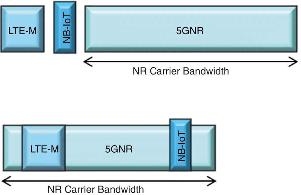
Figure 2.1 LTE‐M and NB‐IoT coexisting with 5G‐NR.
Extended LTE‐M, NB‐IoT, and NR‐IoT provide a rich set of options for massive Machine type of services in the 5G family. Together with eMBB and URLLC, 5G services can cover a wide range of applications. Verticals can classify their use cases into a combination of those three fundamental 5G service categories to speed up execution.
2.2 Networks
5G network architecture [3] is evolving from a point‐to‐point architecture to a service‐oriented architecture. This enables a more refined standardized virtualization platform, allowing intelligence to allocate features and services at core and various edges to support diversified applications.
In 5GC, user equipment (UE) connection to RAN is controlled by Access and Mobility Management Function (AMF) through NG‐C interface as illustrated in Figure 2.2. The AMF includes the network slice selection functionality. User traffic data is connected to Data Network (DN) through User Plane Function (UPF) through NG‐U interface, which is controlled by Session Management Function (SMF). Comparing with the Mobility Management Entity (MME) in Evolved LTE Packet Core (EPC), the separation of access control plane (CP) and session management of user plane (UP) in 5GC provides greater flexibility and scalability, particularly for CP only traffic or non‐IP session applications. Serving and Packet Gateway functions in EPC are separated as GW‐C and GW‐U, supported by SMF and UPF, respectively. Thus, it allows independent scalability, evolution and flexible deployments, e.g. centralized location or distributed (remote) location.
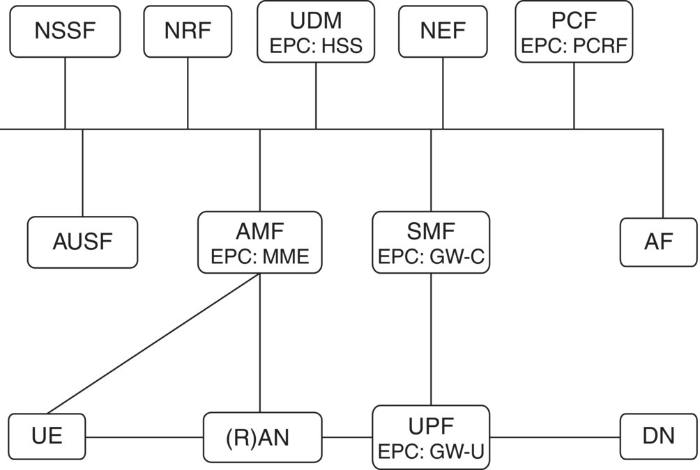
Figure 2.2 3GPP 5G architecture.
The Policy Control Function (PCF) provides a policy framework incorporating network slicing, roaming and mobility management, similar to the Policy and Charging Rules Function (PCRF) in EPC in LTE. Application Function (AF) requests dynamic policies and/or charge control. The Unified Data Management (UDM) stores subscriber data and profiles, similar to Home Subscriber Server (HSS) in LTE.
2.2.1 5G Network Architecture
The 5G network can be deployed as a standalone (SA) network based on 5G core or leverage existing EPC as a non‐standalone (NSA), as illustrated in Figure 2.3. 5G‐NR will be deployed with NSA first to leverage existing core network and extensive LTE coverage. Thus the initial services will be eMBB, followed by 5GC for additional services and capabilities.
The RAN and the core network components, network management and controller, as well as application servers are based on more general‐purpose hardware, dynamically configurable under software‐defined networking (SDN), as illustrated in Figure 2.4. The choice of general‐purpose hardware and thereby the cloud implementation facilitates operators' provisioning of various services under a common physical platform, enabling resource sharing, service integration, and customization.
Differentiated services can be supported through end‐to‐end network slicing defined in 3GPP [3]. The network slicing allows dedicated virtual networks with functionality specific to the service or customer over a common network infrastructure. Each network can be identified by Network Slice Selection Assistant Information (NSSAI). Network Slice Selection Function (NSSF) assists in the selection of suitable network slice instances (NSIs) for users and services. These network functions (NFs) and services are registered in a Network Resource Function (NRF). Network Exposure Function (NEF) acts as a centralized point for service exposure and authorizing all access requests from external systems. AMF is responsible for access authentication and authorization, mobility management and termination of CP interface and Non‐Access Stratum (NAS). SMF supports session management, IP address allocation and management, selection and control of UPF, and QoS management.

Figure 2.3 NSA and SA architecture.
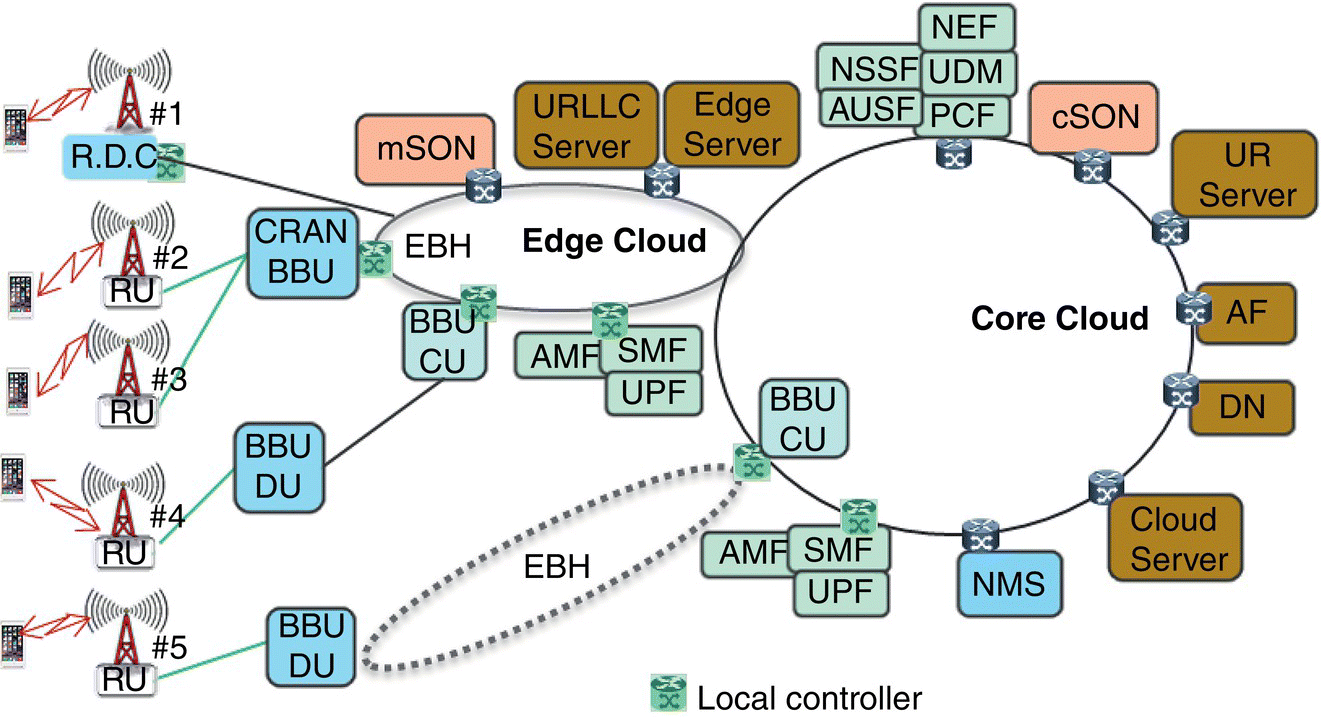
Figure 2.4 5G commercial network deployment architecture.
A network slice corresponds to a dedicated set of resources that can meet a specific performance. A device can be simultaneously connected to multiple network slices. The NSSAI can be provided by UE or directed by a network controller. The NSSAI comprises SST and Slice Differentiator (SD). The SST refers to the expected network behavior in terms of features and services, as illustrated in Table 2.1. The SD is optional information that allows further differentiation by service providers.
Within each network slice, a packet data session could be further differentiated by a QoS flow. The QoS flow is identified by a QoS Flow ID (QFI). Each QoS flow is associated with 5G QoS Indicator (5QI), Allocation and Retention Priority (ARP), and Transport QoS marks (e.g. diffserv). On downlink, UPF uses policy from PCF and SMF to identify flows and adds QFI tag that RAN maps to data radio bearers (DRBs). On uplink, UE uses either signaling or “reflective” learning approach to learn and map QFI to DRBs. Hence, RAN and UPF police DRB mapping and QFI usage accordingly. In the example in Figure 2.5, UE1 has only one network slicing, severed by the network slice 1 through RAN and 5GC Core, while UE2 has slices 1 and 2, served by the RAN and 5GC core slices 2 and 3, respectively. Within each RAN slice, the radio resource is controlled by QoS flow, with a slice‐aware scheduler. The mapping of slicing and QoS flow is essential for service quality.
The variety of services can be supported by distinguished network slicing, either UP or CP functions at far edge, edge center, or cloud data center. Network slicing implementation is end‐to‐end with different instances across radio, transport, core, edge and central clouds.
SDN and network function virtualization (NFV) virtualize the core network elements and functions in each slice to meet its own requirement. Core network components on both CP and UP can be pushed toward radio access point, edge cloud or core cloud with various levels of latencies. CP data can be directly carried over AMF. Packets over UP can be transmitted over UPF controlled by SMF and AMF.
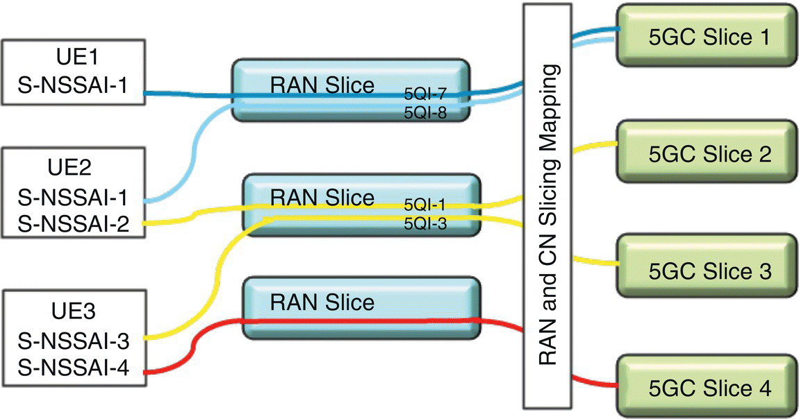
Figure 2.5 Network slicing.
In the RAN, slicing can be built on physical radio resources (e.g. transmission point, spectrum, time) or on logical resources abstracted from physical radio resources, autonomously configured and optimized using SON. The radio access functions can also be physically located at various edges for maximal radio efficiency. This includes traditional integrated base station, or separated radio and baseband units. The standardized interfaces allow more splitting combinations among radio unit (RU), distributed unit (DU) and central unit (CU), as illustrated in Figure 2.6. F1 interface between DU and CU, as well as E1 interface between CU control plane (CU‐CP) and CU user plane (CU‐UP) are specified in 3GPP. A common CU‐CP will control various DUs in one next generation NodeB (gNB), select an AMF based on required NSSAIs, and direct UP traffic to various CU‐UPs at different locations depending on latency and service requirements.
The commercial deployment architecture illustrated in Figure 2.4 shows several deployment options for cell sites based on service requirement. The cell site #1 has integrated radio, digital, and CUs directly connected to edge cloud, while sites #2 and #3 have RUs only connected to Centralized RAN (CRAN). The cell sites #4 and #5 have radio and digital units connected through F1 interface to edge and core clouds, respectively.
In the case of URLLC, the UP/CP functions and application servers could be located at edge cloud or even at access nodes to meet the latency requirement of even less than 10 ms, without dependency on the rest of the operator's transports and core networks. AMF/SMF/UPF and URLLC servers can be implemented physically or virtually at customer sites or virtually through operator data centers. Ultra‐Reliable server that does not require stringent latency could reside at core cloud.
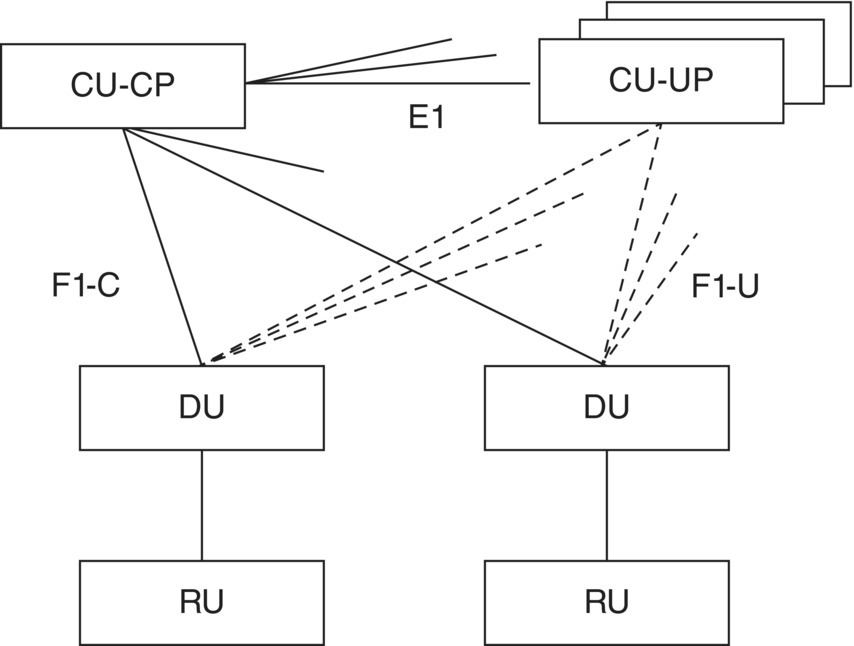
Figure 2.6 3GPP 5G‐NR RAN architecture and interfaces.
While the network is transforming to a service‐oriented architecture, NMS is also evolving from traditional pure network performance monitoring to a fully autonomous 5G network. Various self‐configurations, self‐optimizing, and self‐healing mechanisms enable zero‐touch network provisioning and minimize human intervention from installations to commercial operations. Those SON mechanisms will be discussed further in the following sections.
5G network architecture allows one physical network to be sliced logically into multiple virtual isolated networks. Each slice can be optimized independently to serve a specific vertical application with various QoS flows. Thus, 5G networks provide a high degree of flexibility to enable MEC and virtualized radio access for a variety of services.
2.2.2 Multi‐Access Edge Computing Network
The virtualized network and application servers can be tailored to a variety of vertical markets. It allows operators to create new value‐added services for their customers with less dependency on the underlying hardware, making it transparent across the entire network. It enables low‐latency and ultra‐reliable services by pushing core network components and servers toward edge for MEC.
Cloud servers enhance network efficiency through resource pooling, and improve time‐to‐market for innovative services. However, they also introduce latency and uncertainty on routing. Edge servers enhance the latency but increase the cost and complexity by adding computing, caching and other service functions at the edge. They also introduce challenges for mobility. Thus, it is essential to have a local controller at various tiers of edge clouds to determine the proper routing and content transitions.
An agile way to direct traffics based on a loss function of latency and serving‐node cost is proposed. The latency driven routing and service platform are enabled through a multi‐tier MEC which includes a far‐edge server, edge‐cloud server, and a wide‐area core cloud server. The controller for this service platform can be co‐located with integrated base station at far‐edge, CRAN at edge cloud, or wide‐area core cloud as illustrated in Figure 2.4. Device service profile and routing authorization are used to direct a service.
The loss function is derived from latency, and service node cost for a device at its specific location i, denoted as Delayi and Costi, respectively. The cost includes the network resource needed for:
- Content preparation, e.g. content availability, content popularity, and replication of content across localized MEC servers.
- Transport cost associated with UE location, mobility.
- Caching and computing.
Thus, the selected route j (????_route????) is the lowest loss function route, that is
The selected route shall meet the targeted latency with minimal loss functions, as illustrated in Figure 2.7. Various hider‐layers can be utilized. Supervisory learning can be introduced first before autonomous operation. The co‐location of 5GC with access node can achieve latency of less than milliseconds and reliability at 99.999%. The default cloud based 5GC enables more efficient resource pooling with eMBB in latency beyond 50 ms.
Mobility for MEC is challenging as the server is localized. The 5GC has enhanced session and service continuity (SSC) through various means; the three SSC modes are [3]:
- SSC mode 1: the network preserved the continuity service provided to the UE with the same PDU IP anchor maintained for the duration of UE attachment. This is similar to 4G LTE.
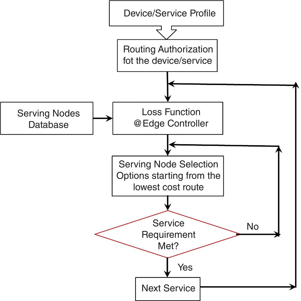
Figure 2.7 Flowchart for MEC mobility with multi‐tier edges.
- SSC mode 2: the network may release the connectivity service delivery to the UE. The IP address is not preserved, and the existing session will be ended.
- SSC mode 3: A new PDU IP anchor is established when UE moves in the network. The previous PDU IP anchor is maintained until a new PDU IP anchor point is established. The new connection will be established before the existing session ends.
For use plane application, 5GC can also support breakout UPF using Uplink Classifier Rules for traffic steering to route selective traffic to the local MEC platform for low‐latency applications directly. CP applications need to be directed by NSSF through NSSAI.
5GC enables MEC at various radio access and core nodes for a variety of applications. It also supports various traffic steering, session and service continuality.
2.2.3 Virtualized Radio Accesses
RAN virtualization can maximize hardware and radio resource efficiency through pooling and tightly coordinated radio resource allocation. Virtualizations broaden the 5G ecosystem with more innovated solutions from more players. Radio access virtualization is enabled through standardized interfaces between CU and DU. Different RAN functional CU‐DU splits are under intensive investigations by both academics and industry fora. The CU can also be separated into CP and UP to allow more dynamic resource control.
The splitting of RAN architecture into CUs and DUs needs to cater for different deployment scenarios and challenges, including supporting the introduction and evolutions of various RAN capabilities, such as coordinated/joint processing, massive MIMO, advances receivers, etc. It is also required to facilitate new application developments and allow business innovations, such as eMBB, cellular V2X services, mMTC devices, and so on. The splits should further attempt to minimize front‐haul throughput requirements scaling as a function of user throughputs.
3GPP has defined various split options between CU and DU based on the reference models in [19, 20]. The most widely studied split options are illustrated in Figure 2.8.
Option 2 has Radio Resource Control (RRC) and Packet Data Convergence Protocol (PDCP) in CU; while Radio Link Control (RLC), Medium Access Control (MAC), Physical layer and RF are in DU. This has been standardized as F1 interface in 3GPP [21]. Option 7 splits within Physical layer, while Option 8 is the traditional Physical layer and RF layer split as typically defined by the Common Public Radio Interface (CPRI) interface. Various low‐layer splitting has been studied in 3GPP [22].
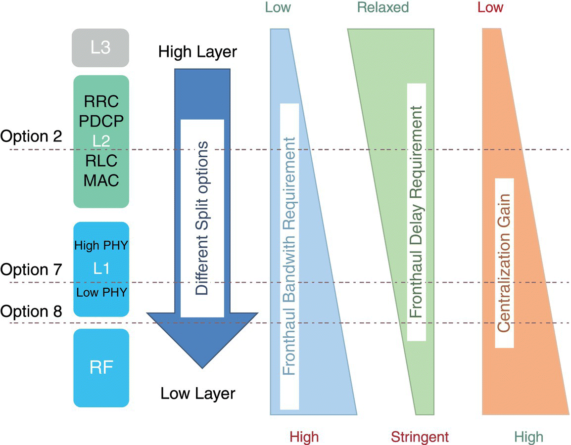
Figure 2.8 RAN splitting and performance tradeoff.
The standardized splitting can broaden the ecosystem as illustrated in Figure 2.4. Traditional macro‐cell product from one single supplier can be broken into various radio, distributed, and CU products with various combinations. Those function elements can also be built on general hardware to allow virtualized radio access at RU, edge cloud, or center cloud.
The different split options determine the tradeoff between front‐haul bandwidth and latency requirements as well as the centralization gains due to improved cell coordination capabilities as indicated in Figure 2.8. The lower the split point the higher the front‐haul bandwidth required, the more stringent the font‐haul delay is needed, and hence, the higher the centralized spectral efficiency gain. These split options and their variations present different deployment opportunities and challenges. While specifying more split options would mean greater deployment flexibility, inter‐operability and building of the ecosystem becomes more difficult. Therefore, it is generally agreed that the standardization of two to three split options should be a good compromise between deployment flexibilities and development complexities.
High‐layer split is particularly attractive for mmWave due to its moderate transport bandwidth requirements. Specifically, F1 interface has similar bandwidth requirements as user data rates and can tolerate a more relaxed latency of 1.5–10 ms compared with other lower layer split options. Hence, it supports a wide range of deployment scenarios. Low‐layer split is critical for resource allocation and interference mitigation with tightly coordinated transmission and receive for sub‐6 GHz. The high‐layer split also provides the opportunity for network management to direct traffic flexibly at a high‐layer aggregation point based on service requirements.
Option 2 for higher layer split and Option 7 for lower layer split provide logical compromises in terms of transport requirements, support of coordinated RUs, RAN virtualization, and application specific QoS settings. This encourages more innovative solutions in advanced radio components, sophistic baseband processing, and radio resource management.
Virtualized end‐to‐end network functionalities from radio to transport to core and server will provide opportunities for operators and verticals to define a distinct and isolated logical network of individual use cases in real‐time, built upon a shared physical wide‐deployed commercial infrastructure. This can be an ultra‐reliable low latency service at the far edge for superior reliability and performance. Alternatively, it can leverage the wide‐area 5G NR eMBB service for a cost efficient way of connections of everything. The 5G network can be readily configured as a private low‐cost and high‐performance network for verticals. Thus it provides enormous business opportunities for operators and verticals.
2.3 Service‐Aware SON
An autonomous intelligent service‐aware SON is required for the 5G network with control functions at radio, baseband DU, higher layer CU, and various edge and core servers. The flexible 5G architecture and radio access schemes increase the complexity of network management, with increased spectrums and network densifications. Standardized CU‐DU splitting also provided more opportunities to control radio transmissions. The large intensified scope of network coordination, configuration and management has evolved to a level beyond which engineers can handle.
The performance data of the 5G NF are fundamental for network monitoring, assessment, analysis, optimization, and assurance. A variety of communication service instances are provided by multiple NSIs. The different parts of an NSI are grouped as Network Slice Subnets (e.g. RAN, 5GC, and Transport) allowing the lifecycle of a Network Slice Subnet Instance (NSSI) to be managed independently from the lifecycle of an NSI.
A SON framework is illustrated in Figure 2.9. SON consists of self‐configuration, self‐optimization, and self‐healing. It is driven by consumers and services. The 5G SON function consists of the provisioning management services [23], performance data file services [24], and fault supervision data report management service [23] to collect the management and network data from the management services produced for NF, NSIs, and NSSI. Cell trace data are also very critical to improve SON performance [25]. Based on the collected data, the SON function will analyze the network behavior, status, and traffic pattern, among others, to determine the actions needed to optimize the networks.

Figure 2.9 Service consumer‐based SON.
An intelligent service‐aware SON is required to optimize the services delivery and network performance, such as reliability and latency, autonomously in real‐time. Various ML algorithms are essential to take advantage of a large amount of big data, engineering rules and learning. The initial parameters and network configuration should be settable by experts to enable ML achieving local optimal points faster, and better approaching global optimum points. The ML inputs, hidden layers and loss functions are highly dependent on various services and network key performance indicators (KPIs). ML algorithms shield the complexity of physical and virtual NFs from higher layers to aid engineers.
Various ML algorithms in terms of supervised learning, unsupervised learning, and reinforcement learning are described in ML surveys [9, 10]. The dominated algorithm is Q‐learning using the reinforcement approach, while the algorithm is driven by real‐time network performance data reinforced by feedback from past execution results. Although limited applications have shown some preliminary successful use cases, current SON is still behaving less intelligent than experienced engineers. More intelligent and further inputs from end‐to‐end services and consumer device performance metrics need to be included in those algorithms. Combining machine‐level insights with human insights should be exploited further to balance human and machine decision making.
Service‐aware SON is needed beyond traditional distributed function at eNB and centralized function at NMS level to form an intelligent hybrid SON with radio control functions at core and various edges.
2.3.1 5G‐NR SON Control
5G‐NR can enable SON functionality beyond just eNB and NMS levels [26–30]. Traditional SON with functions at base station and NMS has proven a valuable component in network operations. More sophistical autonomous network control is required for the 5G network to ensure overall optimized performance under operator's policy control. A finer resolution under NMS level is possible through the high‐layer CU‐DU splitting F1 interfaces defined in 3GPP [21]. A new fast response mSON at CU is proposed to utilize the F1 interface and control DUs.
SON functionalities at base station require fast feedback. They are dependent on real‐time feedback from devices, such as RRC connection messages between eNB and UE, radio conditions reported by UE. The feedback could be handover messages in tens of millisecond interval, or Channel Quality Indicator (CQI) at TTI level. Major self‐optimization functions include Automatic Neighbor Relations (ANR), Mobility Robustness Optimization (MRO), Mobile Load Balancing (MLB), and Coverage and Capacity Optimization (CCO). The ANR is defined in 3GPP TS32.511 [28], with others in TS32.521 [29].
cSON functionalities are functions that would require cluster level information. Those would need coordination and relationship among cell sites in a large time interval. Performance Management typically pulls data in a 15 min interval, while call trace in a 1 min interval. Centralized functions will take into account cluster information to optimize the parameter from an overall network perceptive. cSON can further improve eNB functions, and expanded optimization functions at cluster level, such as load balancing among cells and antenna tilting optimization. The cSON can also utilize end‐to‐end latency measurement to improve Voice over LTE (VoLTE) coverage by dynamically adjusting the number of HARQ retransmissions [31].
Both eNB SON and cSON are needed to ensure proper performance of a network. For example, ANR at eNB can automatically add new sites, and avoid call drops. Centralized ANR will oversee the eNB ANR functions, automatically remove non‐used neighbors, or add must have neighbors. One use case is a distance neighbor overshadowing a nearby neighbor and being wrongfully detected by UE. This could end up with ping‐pong between source and target cell sites, or cause call drops. The centralized function can remove or deny this neighbor from the neighbor relationship, updating the blacklist to prevent this happening. CCO optimize cell site transmit power, antenna tilting, and others to relieve congestion and fill coverage holes. Those changes could also impact ANR, MRO, and MLB at both cSON and dSON. Thus, the feature coordination and KPI safeguard are important to avoid any unnecessary over‐optimization.
The mSON is suitable for local breakout to enable low latency applications, as well as spectrum sharing under sub‐second level. It is complementary to the current dSON at the base stations and the cSON functionality at NMS level. It can conduct traffic steering, QoS provisioning, dual connectivity, and spectrum sharing at a finer granularity, while enable handover and load balancing at a cluster level.
The mSON can take full advantage of the F1 interface to facilitate spectrum sharing, carrier aggregation, and dual connectivity among various frequency carriers as illustrated in Figure 2.10a. 5G expands the frequency bands beyond traditional low‐bands and mid‐bands. The challenging with fast inter‐frequency MRO at eNB and a much longer term load balancing among the same carriers at cSON becomes more sophisticated in the 5G network. Therefore, mSON will be in a unique position to enable a fast MRO and MLB, not only from an individual cell and neighbors but also from a cluster point of view. As 5G deployments start on high‐band for increased capability and ultra‐low latency, dual access links are expected to combine with low and mid‐band for increased wide‐area coverage. When 5G is maturing, high‐band combining with mid‐band and low‐band can maximize coverage, capacity, and cell edge performance.

Figure 2.10 Spectrum sharing and multiple links.
Various access options for combining access links for spectrum sharing are illustrated in Figure 2.10b. They can be break‐before‐make, and only maintain a single link on a spectrum at a time. It can also use eLTE/EPC as the primary link and 5G as the secondary link in 5G early deployment NSA mode, and then using NR/5GC as primary link and eLTE as the secondary link to preserve the LTE investment in SA mode. As 5G‐NR is growing, both NR and NR access links can be used for maximal capacity. The Xx interface is referred to as X2 for NSA, and Xn for SA, respectively. The combination can be either dual connectivity among non‐collocated cells, or carrier aggregation on collocated cells. Shared and unlicensed spectrum will be utilized to further improve user experience.
As the mSON is collocated with CU, it can coordinate radio and transport resource to reduce any potential congestion, and optimize access and backhaul routing. Being close to where access is happening, it can optimize network slicing for a specific customer to achieve desired user experiences. The mSON can work together with cSON to control traffic routing either locally or through the cloud based on latency, reliability, and other service requirements. It can work closely with dSON to determine the level of power boosting and retransmission or repetition to meet the latency and reliability requirements.
mSON can coordinate well with cSON on network orchestration and dSON on dynamic real‐time optimization. mSON is going to play an important role in utilizing resources more efficiently as spectrum and access links increase.
2.3.2 An Intelligent Hybrid 3‐Tier SON
By combining traditional SON with mSON, the scope of SON functionalities is expanded. In particular, with the introduction of the DU‐CU splitting interfaces at both high and low layers; an intelligent 3‐tier SON can autonomously optimize the 5G network at various layers.
Lower‐layer split defined a standardized interface among DU and RU, therefore, it opens the possibility to control distributed RUs from a broader ecosystem. This low‐latency radio coordination will maximize spectral efficiency and mobility performance among multiple transmission points. It will enable coordinated multiple transmission point features across entire RAN, even for RUs from different manufacturers.
With the addition of lower‐layer split, a fully coordinated radio resource management at three different latency levels can be enabled as illustrated in Figure 2.11. The dSON functionality can operate at 250 μs over lower‐layer interface, mSON functionality at less than 50 ms over F1 interface, and cSON functionality at above 1 s over north‐bound network management interface.
This intelligent hybrid 3‐tier SON expands traditional eNB SON function to multiple vendors through standardized lower‐layer splitting for provisioning, optimizing, and healing among RUs. It introduces mSON functions for tightly coordinated dual connectivity and spectral sharing, enabling traffic steering for low latency application among various digital units. It refines the cSON for overall RAN efficiency and performance.
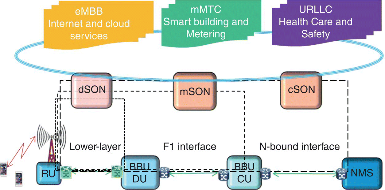
Figure 2.11 Intelligent hybrid 3‐tier SON.
Operators will define policy with the relative weights for each cell in a centralized database. Those weights could be a combination of RF characteristics and services. The RF characteristics include traditional path‐loss, received signal strength or signal‐to‐interference‐plus‐noise ratio, network loading characteristic and inter‐frequency path‐loss discrepancies, operator biasing, and restricted and default values. The service weights could be relative latency, throughput, reliability requirement, and user QoS levels. Several algorithms could also try to optimize the same parameter. The final adjustment could be a combined decision at various levels, and limited to a preset boundary. Those boundaries could be the hard or soft limitation for a particular parameter, e.g. maximal tilting at a RET antenna or a handover parameter. The final changes at eNB could be based on historic and current proposed changes from the distributed, middle and centralized algorithms:
where P(t) is the eNB parameter adjustment. Pc(t), Pm(t), and Pd(t) are the proposed change by centralized, middle‐tier algorithm, and eNB algorithm at time t, respectively.
The dynamic control mechanism for multiple layer self‐optimizations can execute each layer in an iterative manner triggered by a defined number of events or time periods needed for each layer of optimizing algorithm. Each layer defines operation boundaries of lower layers, a set of eNB parameters and value ranges to optimize upon. A convergent optimized network parameter value is iteratively achieved.
The 3‐tier SON is essential to support services with various reliabilities and latencies. A higher reliability application demands higher transmission fidelity leading to a more confined coverage [5]. Therefore, it changes the cell boundary with increased handovers and overall interference levels at dSON. Concurrently, it requires intensive traffic steering and mobile routing at mSON, as well as increased end‐to‐end resource allocations at cSON.
A unified radio architecture supports programmable radio access components, transport components, and core and cloud components. The hybrid 3‐tier SON will allow intelligent control of resources for various applications enabling autonomous MEC at various edges and core networks.
2.3.3 Service‐Aware Access Scheme
Operator and vertical provider play an essential and more active role to ensure smooth and coordinated operations of various SON features among a large number of configurable components. An intelligent autonomous network requires a coordinated control system at various layers, among RUs, CUs and DUs, various core network components and NMSs. Operators define a centralized policy management and SON orchestration that include targeted key network and service performance metrics and boundaries of various parameters for various services.
The level of benefits depends on interaction between human and machine insights. Automation is as important as optimization in a commercial operational network. 5G architecture and DU‐CU splitting provided enablers to support configurable access schemes based on end‐to‐end application characteristics and service requirement.
Since QoS profile is available in 5G radio access nodes, the selection of dual connection among 5G‐NR and enhanced LTE (eLTE) could include user applications and service requirements, on top of coverage and radio KPIs. This will improve the user quality of experience (QoE) with most efficient uses of network radio and hardware resources.
The mSON mechanism can control the aggregation point of dual connectivity among 5G NR and eLTE. This control mechanism can be adjusted for different network slicing. It can detect device traffic type from transmitted data pattern through deep learning. It maps radio bearers to various packet data sessions with differentiated treatment based on QFI/5QI.
The mechanism can activate various access technologies based on location and radio access coverage availability. For example, it redirects traffic to mitigate the blockage of mmWave or by using eLTE for coverage challenging areas. The device and service profile will inform the device feature and service capability. A latency tolerant large data transmission will be switched at core to reduce resource consumption. A latency sensitive transmission will be dual connected and aggregated at co‐located distributed BBUs, e.g. high‐fidelity video. The IMS‐based service, or voice service will be directed to eLTE only initially as voice service is not supported in initial NSA specification. The flow chart for this mechanism is illustrated in Figure 2.8.
This processing is continuously performed for all data transmission on an ms interval to maximize performance and efficiency. It activates the selected type of dual connectivity based on coverage, delay requirement, and traffic pattern.
The mechanism in Figure 2.12 minimizes radio and hardware resources while maximizes user performance. The dual connectivity is only enabled for applications requiring large data throughput with low latency at initial 5G launch.
The service‐aware access scheme can maximize radio resource utilization and hardware efficiency by analyzing a large amount of network performance data to meet the service requirement. It can reduce unnecessary handover and signaling, consequently improving user experience.
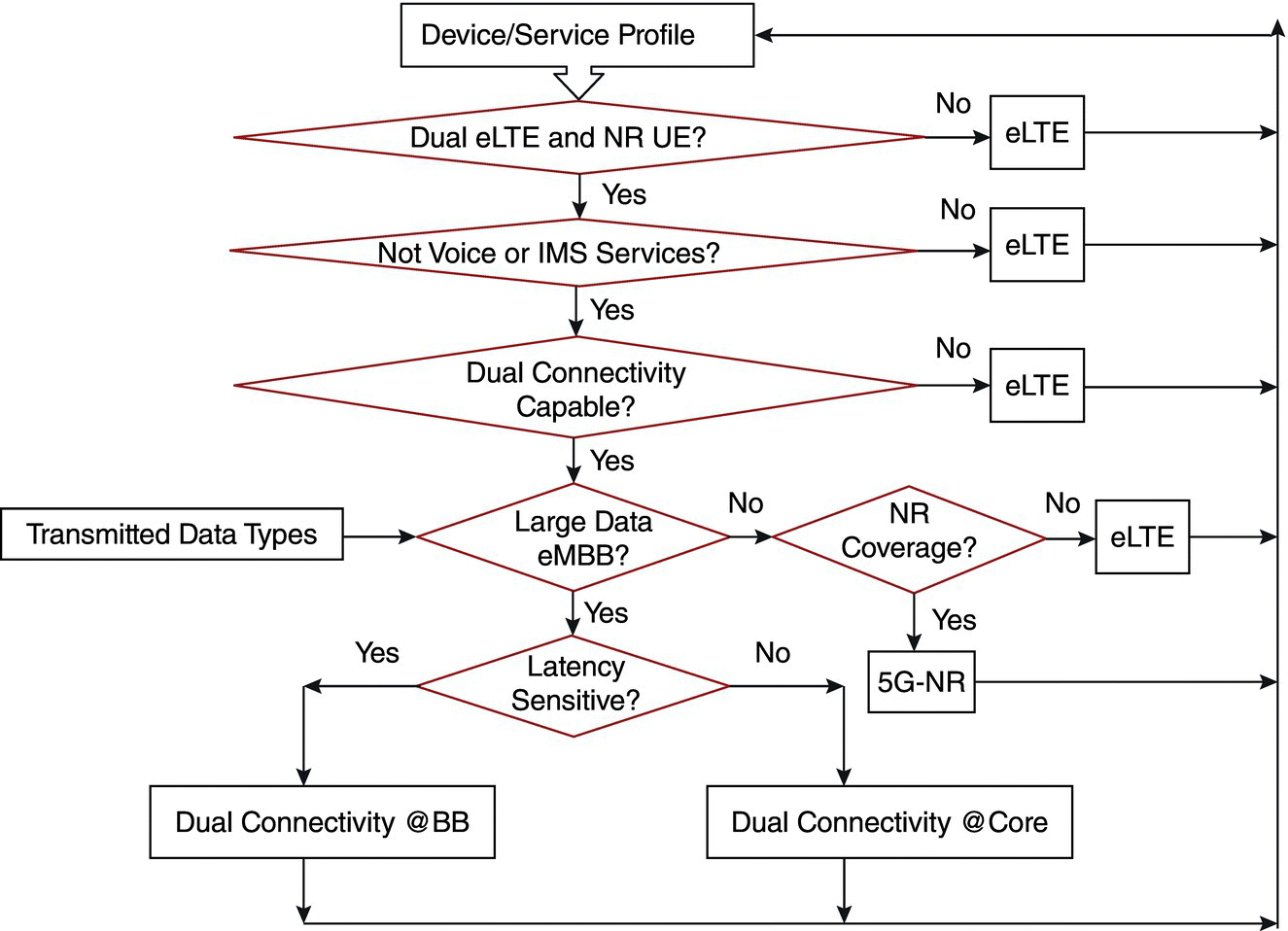
Figure 2.12 Flow chart of application driven 5G‐NR and eLTE dual connectivity.
2.3.4 Performance Benefits
An intelligent autonomous network can adjust access means according to network dynamic user and service environment. This improves overall performance. Massive MIMO, an important component of 5G, is used to illustrate the performance benefits.
As network and device increase the number of transmitting and receiving antennas, cell configuration and beam pattern for each site and each user needs to be optimized as well.
The low‐layer splitting makes it possible for centralized baseband and dSON to control the RUs from various manufacturers. The beam shaping could be controlled through the m‐plane defined in xRAN or low‐layer splitting in 3GPP. It can optimize the beam shaping based on cell site configurations and RF characteristics. xRAN has defined digital beamforming in terms of beam Indices, Real‐time weights and UE channel information through one or multiple profile files [32,33]. Those files can be modified by SON mechanism through NetConf/Yang model. 3GPP has also completed its study report on SON for an Active Antenna System [34].
RU with advanced massive MIMO capability can change the angle and width of the main lobe, as well as relative power ratio and suppression to various side lobes based on control parameters passing though low‐layer interface from digital and central units. There are multiple beam patterns associated with massive MIMO, such as beam patterns defined in 3GPP Release 10 for Common Reference Signal (CRS) shown in Figure 2.13. SON can optimize the network performance by selecting the right beam pattern. For example, a vertical user dominant downtown skyscape would be more efficient from the vertical top beams in Figure 2.13, while a hot spot could gain more capacity from a bottom sharp beam created in the right‐hand side antenna azimuth pattern.
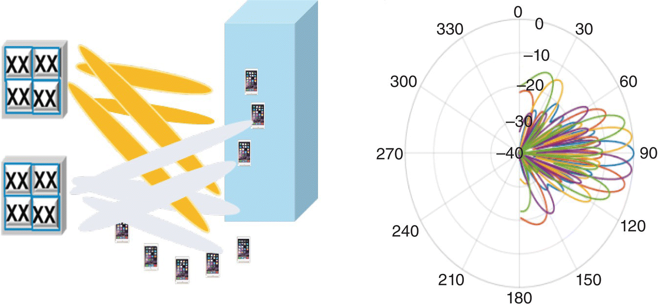
Figure 2.13 Antenna beam patterns.
Table 2.2 Performance optimization from various beam patterns.
| BP#1 | BP#2 | BP#3 | BP#4 | Optimized | |
| Spectral efficiency (%) | 13 | 19 | 22 | 27 | 27 |
| Average UE data rate (%) | 111 | 154 | 176 | 165 | 176 |
| UE rate <1 Mbps (%) | –60 | –70 | –69 | –69 | –70 |
| PDCCH CCE utilization (%) | –2 | –18 | –22 | –25 | –25 |
| DL RLC latency (%) | –46 | –56 | –55 | –55 | –56 |
SON performance benefit is illustrated in Table 2.2 from field results in a commercial trial network. The optimized beam pattern could double the spectral efficiency and average user data rate as compared with default beam pattern for existing legacy devices. Control channel utilization can also be reduced by 20%. In particular, the percentage of users getting low throughput is reduced dramatically. The optimized network configuration also depends on the objective of operator or vertical partners. Beam pattern 4 (BP#4) could provide the best cell capacity, while beam pattern 2 (BP#2) could provide the least number of users with data rate less than 1 Mbps.
Intelligent autonomous operations relieve engineers from a large amount of data, and the complexity of physical and virtual NFs. They can significantly optimize the user and network performance, increase the capacity and enhance the connectivity.
The service‐aware SON provides vertical opportunities to define required key performance metrics and optimization criteria for network operation and management. The network operations and SON will act differently for specific vertical applications to maximize benefits for verticals.
2.4 Summary
5G wireless networks have fundamentally evolved from communications between humans to an intelligent service delivery platform that can connect everything. The 5G flat network architecture and standardized high‐layer RAN split F1 interface allow more flexible service delivery and a broader ecosystem. An intelligent mobile edge network with a hybrid 3‐tier SON will enable autonomous engineering and operation. This is essential to support less than millisecond ultra‐low latency applications at 99.999% reliability, on top of eMBB and mMTC.
Verticals can classify their use cases into a combination of those three fundamental 5G service categories to speed up their implementation. Virtualized end‐to‐end network functionalities will provide opportunities for operators and verticals to define a distinct and isolated logical network of individual use cases in real‐time, built upon a shared physically wide‐deployed commercial infrastructure. This can be an ultra‐reliable low latency service at the far edge for superior reliability and performance. Alternatively, it can leverage the wide‐area 5G NR eMBB service for a cost effective way for connections of everything. The 5G network can be readily configured as a private low‐cost and high‐performance network for verticals. Thus it provides enormous business opportunities for operators and verticals.
The service‐aware SON will further provide verticals opportunities to define key performance metrics and optimization criteria for network operation and management. Thus, the mobile wireless network is transforming into an intelligent multiple‐purpose autonomous 5G network for a variety of vertical services.
Acronyms
- 5G
- Fifth generation
- 5GC
- 5G core
- 5G‐NR
- 5G New Radio
- 5QI
- 5G QoS Indicator
- AF
- Application Function
- AMF
- Access and Mobility Management Function
- ANR
- Automatic Neighbor Relation
- AR
- Augmented Reality
- ARP
- Allocation and Retention Priority
- BBU
- Baseband Unit
- CCO
- Coverage and Capacity Optimization
- CP
- Control plane
- CPRI
- Common Public Radio Interface
- CQI
- Channel Quality Indicator
- CRAN
- Centralized RAN
- CRS
- Common Reference Signal
- cSON
- Centralized SON
- CU
- Central Unit
- DL
- Downlink
- DN
- Data Network
- DNN
- Data Network Name
- DRB
- Data Radio Bearer
- dSON
- Distributed SON
- DU
- Distributed Unit
- EBH
- Ethernet Backhaul
- eLTE
- Enhanced LTE
- EPC
- Evolved Packet Core
- ETSI
- European Telecommunications Standards Institute
- FDD
- Frequency Division Duplex
- gNB
- Next generation NodeB
- GW‐C
- EPC Gateway control plane function
- GW‐U
- EPC Gateway user plane function
- IMS
- IP Multimedia Subsystem
- IoT
- Internet of Things
- KPI
- Key performance indicator
- LDPC
- Low‐density parity‐check
- LTE
- Long‐Term Evolution
- LTE‐M
- LTE Cat‐M1 or Long Term Evolution (4G), category M1
- MAC
- Medium Access Control
- MEC
- Multi‐access edge computing
- ML
- Machine Learning
- MLB
- Mobility Load Balancing
- mMTC
- Massive Machine Type Communications
- MRO
- Mobility Robustness Optimization
- mSON
- Middle‐tier SON
- NB‐IoT
- Narrowband Internet of Things
- NEF
- Network Exposure Function
- NF
- Network Function
- NFV
- Network Function Virtualization
- NG‐C
- Next Generation Core, control plane
- NG‐U
- Next Generation Core, user plane
- NR
- New Radio
- NRF
- Network Repository Function
- NR‐IoT
- New Radio‐Internet of Things
- NSSAI
- Network Slice Selection Assistance Information
- NSSF
- Network Slice Selection Function
- NSSP
- Network Slice Selection Policy
- PCF
- Policy Control Function
- PDCP
- Packet Data Convergence Protocol
- QFI
- QoS Flow Identifier
- QoE
- Quality of experience
- QoS
- Quality of service
- (R)AN
- (Radio) Access Network
- RLC
- Radio Link Control
- RRC
- Radio Resource Control
- RU
- Radio Unit
- SA NR
- Standalone New Radio
- SCS
- Subcarrier Spacing
- SD
- Slice Differentiator
- SDN
- Software‐defined networking
- SMF
- Session Management Function
- S‐NSSAI
- Single Network Slice Selection Assistance Information
- SON
- Self‐Organizing Network
- SSC
- Session and Service Continuity
- SST
- Slice/Service Type
- TDD
- Time Division Duplex
- TTI
- Transmission Time Interval
- UDM
- Unified Data Management
- UE
- User equipment
- UL
- Uplink
- UP
- User plane
- UPF
- User Plane Function
- URLLC
- Ultra‐reliable and low‐latency communications
- V2X
- Vehicle‐to‐everything
- VR
- Virtual reality
References
- 1 Signals Research Group (2018). 5G: the greatest show on Earth, Vol. 14, No. 8.
- 2 3GPP TS 38.201‐36.215 (2017). 3GPPP, Technical Specification Group, Radio Access Networks; NR; Physical Layers; Release 15, December 2017.
- 3 3GPP TS23.501‐503 (2018). System Architecture: Procedures: Policy and Charging Control Framework for the 5G System, V15.3.0, 2018‐09.
- 4 Kekki, S., Featherstone, W., Fang, Y. et al. (2018). MEC in 5G networks. http://www.etsi.orgimages/files/ETSIWhitePapers/etsi_wp28_mec_in_5G_FINAL.pdf.
- 5 Sachs, J., Andersson, L., Araújo, J. et al. (2018). Adaptive 5G low‐latency communication for tactile Internet services. Proceedings of the IEEE (October 2018).
- 6 Schulz, P., Matthe, M., Klessig, H. et al. (2017). Latency critical IoT applications in 5G: perspective on the design of radio interface and network architecture. IEEE Communications Magazine 55 (2): 70–78.
- 7 Mwanje, S., Decarreau, G., Mannweiler, C. et al. (2016). Network management automation in 5G: Challenges and opportunities. 2016 IEEE 27th Annual International Symposium on Personal, Indoor, and Mobile Radio Communications (PIMRC).
- 8 Yang, J. and Chan, Y. (2019). Transforming towards an intelligent multiple purpose 5G network. IEEE Communications Magazine 14 (2): 53–60.
- 9 Moysena, J. and Giupponi, L. (2018). From 4G to 5G: self‐organized network management meets machine learning. Computer Communications 129: 248–268.
- 10 Klaine, P.V., Imran, M.A., Onireti, O., and Souza, R.D. (2017). A survey of machine learning techniques applied to self‐organizing cellular networks. IEEE Communication Surveys and Tutorials 19 (4): 2392–2431.
- 11 Y. Ouyang; Z. Li; L. Suet al. Application behaviors Driven Self‐Organizing Network (SON) for 4G LTE networks,” IEEE Transactions on Network Science and Engineering, Year: 2018 1
- 12 Polese, M., Jana, R., Kounev, V. et al. (2018). Machine Learning at the Edge: A Data‐Driven Architecture with Applications to 5G Cellular Networks, arXiv:1808.07647v1 [cs.NI], August 2018.
- 13 Arslan, M., Sundaresan, K., and Rangarajan, S. (2015). Software‐defined networking in cellular radio access networks: potential and challenges. IEEE Communications Magazine 53 (1): 150–156.
- 14 Mountaser, G., Condoluci, M., Mahmoodi, T. et al. (2017). Cloud‐RAN in support of URLLC. IEEE Globecom Workshops.
- 15 3GPP TR 23.799 (2016). Study on Architecture for Next Generation System (Release 14), V2.0.0, November 2016.
- 16 Yang, J. (2018). 5G Wireless. In: Encyclopedia of Wireless Networks. Springer.
- 17 Verizon (2017). State of the IoT Market – 2017. www.verizon.com.
- 18 Yang, J., Song, L., and Koeppe, A. (2016). LTE field performance for IoT applications. Proceedings of VTC (18–21 September 2016). IEEE.
- 19 3GPP TR38.801 (2017). Study on New Radio Access Technology; Radio Access Architecture and Interfaces (Release 14), V2.0.0, March 2017.
- 20 3GPP TS38.401 (2018). NG RAN, Architecture Description (Release 15), V15.3.0, 2018‐09.
- 21 3GPP TS38.470‐474 (2018). NG RAN: F1 General, F1 Layer1, F1 Signaling, F1AP, F1 Data Transport (Release 15), V15.3.0, 2018‐09.
- 22 3GPP TR38.816 (2017). Study on CU‐DU Lower Layer Split for NR; (Release 15), V1.0.0, December 2017.
- 23 3GPP TS 28.532 (2019). Management and Orchestration; Generic Management Services.
- 24 3GPP TS 28.550 (2019). Management and Orchestration; Performance Assurance.
- 25 3GPP TS 32.421 (2019). Telecommunication Management; Subscriber and Equipment Trace; Trace Concepts and Requirements.
- 26 Kakadia, D., Yang, J., and Gilgur, A. (2017). Network Performance and Fault Analytics for LTE Wireless Service Providers. Springer.
- 27 3GPP TS 32.501 (2018). Telecommunication Management; Self‐Configuration of Network Elements; Concepts and Integration Reference Point (IRP) Requirements.
- 28 3GPP TS 32.511 (2018). Telecommunication Management; Automatic Neighbour Relation (ANR) Management; Concepts and Requirements,V15.0.0, 2018‐06.
- 29 3GPP TS 32.521 (2012). Telecommunication Management; Self‐Organizing Networks (SON) Policy Network Resource Model (NRM) Integration Reference Point (IRP); Requirements.
- 30 3GPP TS 32.541 (2018). Telecommunications Management; Self‐Organizing Networks (SON); Self‐healing Concepts and Requirements.
- 31 Yang, J., Liu, A., Elmishad, K. et al. (2018).Dynamic HARQ optimization for Voice over LTE. Proceedings of ICC 2018 (May 2018).
- 32 xRAN Forum (2018).Control, User and Synchronization Plane Specification. http://www.xran.org/resources.
- 33 xRAN Fronthaul Working Group (2018). Management Plane Specification, XRAN‐FH.MP.0‐v01.00, July 2018.
- 34 3GPP TR32.865 (2017). Study on OAM Aspects of SON for Active Antenna System (AAS) Based Deployments (Release 15).
