
9
Connected Automobiles
Murali Narasimha1,* and Ana Lucia Pinheiro2,**
1 Futurewei Technologies, Rolling Meadows, IL, USA
2 Intel Corporation, Hillsboro, OR, USA
Abstract
This chapter focuses on the value that 5G brings to connected vehicles. In particular, the higher data rates and lower latency enable in-vehicle applications that can consume large amounts of data, while low-latency communication can enable fast mechanical control loops. In addition to high data rates and low latency, one key feature of 5G that is particularly relevant to connected vehicles is edge computing. By deploying computing capabilities near the end user, the system can take advantage of localized information, such as map updates and weather notifications. This chapter concentrates in two main use cases: vehicle platooning and high definition maps, and how 5G and edge computing can assist to provide the best experience to the end user. Before discussing the use cases, the chapter describes the five levels of vehicle automation and give an overview of multi-access edge computing, an important feature of 5G that helps enable use cases such as the ones described.
Keywords 5G network; connected automobiles; high definition maps; multi-access edge computing; platoon-based driving; vehicle automation
9.1 Introduction
Anyone who has lived in or near a metropolitan area is aware that our current transportation systems are stretched beyond capacity. The loss of life and damage to property from automobiles is significant [1] and the resulting economic impact is staggering [2]. Additionally, lost productivity due to traffic congestion shows the economic toll on large population centers [3–5]. The US National Highway Traffic Safety Administration (NHTSA) has observed that 94% of vehicular accidents are caused by human error [6]. Of these, 41% are attributed to recognition errors (resulting from inattention, inadequate surveillance, distractions, etc.) and 33% are attributed to decision errors (incorrect assumptions about others' actions, speeding, etc.).
Vehicular transportation has not seen major innovations since the introduction of the modern gasoline engine based vehicles. It is widely recognized now that some of the breakthroughs that enabled pervasive connectivity (such as high bandwidth wireless communication, positioning, machine learning), combined with other emerging technologies can be used to gradually decrease the human involvement in driving. Automation of driving has become perhaps the most significant technology goal of the first half of the twenty‐first century. Two technology areas that form the underpinnings of automated vehicles are:
- Sensing: Sensors such as radar and lidar, and also image recognition systems are necessary for a vehicle to learn of its surroundings.
- Robotics: Planning and executing sequences of precise mechanical actions is necessary for automated driving.
Automated vehicle technology has moved from being a research activity in the area of Robotics to mainstream. Leading technology companies such as Google, Tesla, and Uber are engaged in developing various types of automated vehicle solutions. Most vehicle manufacturers have their own plans and roadmaps toward automated driving and are engaged in various technology trials. Some Advanced Driving Assistance Systems (ADAS) are now available in vehicles (e.g. adaptive cruise control (ACC), lane tracking, emergency braking).
Much of the current generation of automated vehicle technology relies on sensors and associated processing to learn about the changing environment. Cameras and image processing are used to identify traffic situations (e.g. traffic signals), pedestrians, animals, etc. Global Positioning System (GPS) provides absolute positioning information. The data provided by the sensors are inputs to a complex system that determines the appropriate steps to take (course correction, braking, acceleration, etc.) and activates the relevant mechanical controls.
Although sensors are essential for automated driving features, they are hardly a complete solution. The following characteristics generally apply to all sensors:
- Sensors have a short range. Radar, lidar, and cameras all have a line‐of‐sight coverage. As a result, environmental features such as buildings, trees, large vehicles, etc. pose a significant problem since the sensors cannot see past obstructions.
- Sensors can fail to detect problematic situations. Different sensors have different specific weaknesses. Lighting conditions can affect the performance of cameras and weather conditions can affect lidar and radar. Most vehicles that advertise ADAS and self‐driving features today require the driver to be always attentive and able to take control of the vehicle in case of an unexpected event.
- Sensors neither improve traffic flow nor reduce congestion. A vehicle equipped with sensors can be automated (to a degree dependent on the types of sensors used) but still has no information about the intentions of other vehicles in its proximity. Consequently, even if a vehicle is equipped with the most precise sensors, it essentially has to emulate a human driving the vehicle and be prepared for any maneuver that could be performed by a vehicle or pedestrian in the vicinity. This may give the vehicle occupant some comfort by reducing their involvement in driving but it does not solve the larger issues of optimizing traffic flow, reducing travel times, and reducing transportation related energy consumption.
These limitations of sensors have led to studies that envision a combination of sensing and wide‐area communication to enable higher degrees of automation [7, 8]. The exchange of messages between vehicles and infrastructure or direct communication among vehicles may be very beneficial to enhance an ADAS decision making process. The concept of ADAS is illustrated in Figure 9.1. The messages can deliver sensor information recorded by vehicles, and also information locally stored in the vehicle such as high definition (HD) maps.
This chapter focuses on the value that 5G brings to connected vehicles. In particular, the higher data rates and lower latency enable in‐vehicle applications that can consume large amounts of data, while low‐latency communication can enable fast mechanical control loops. In addition to high data rates and low latency, one key feature of 5G that is particularly relevant to connected vehicles is edge computing. Edge computing enables placing intelligence at locations in the network close to the user. The low latency combined with the edge computing capabilities can enable intelligent and fast mechanical control. The high data rates combined with edge computing can make ADAS features more intelligent. By deploying computing capabilities near the end user, the system can take advantage of localized information, such as map updates and weather notifications.
Figure 9.1 Information that may be utilized by an Advanced Driving Assistance System.
This chapter concentrates on two main use cases: vehicle platooning and HD maps, and how 5G and edge computing can assist to provide the best experience to the end user. Before discussing the use cases, we describe the five levels of vehicle automation and give an overview of multi‐access edge computing (MEC), an important feature of 5G that helps enable use cases such as the ones described.
9.2 Levels of Vehicle Automation
In light of the rapid progression toward driving automation, governments and regulatory bodies are grappling with how transportation systems of the future will function. NHTSA has defined five levels of vehicle automation [9] which can be summarized as follows:
- No Automation (Level 0).
- Function‐specific Automation (Level 1): one or more specific control functions (e.g. electronic stability control).
- Combined Function Automation (Level 2): automation of at least two control functions designed to work in unison (e.g. ACC in combination with lane centering).
- Limited Self‐Driving Automation (Level 3): enable driver to cede full control of all safety‐critical functions under certain traffic or environmental conditions; driver is expected to be available for occasional control (e.g. Google car).
- Full Self‐Driving Automation (Level 4): vehicle performs all safety critical driving functions and monitors roadway conditions for entire trip; driver may not be available for control at any time during the trip and includes unoccupied vehicles.
While each successive level of automation represents significant technological advancement, the shift from Level 3 to Level 4 is especially challenging. While Level 3 automation relies on sophisticated interaction between various systems within the vehicle, the input for decision making is the environmental information obtained from the sensors. Level 4 brings in more challenging scenarios which may not be foreseeable by the sensors. In particular Level 4 automation requires: (i) environmental knowledge beyond the limits of the sensors on the vehicle, and (ii) combining and interpreting different streams of information to make and implement decisions as well as or better than a human driver. The usage of up‐to‐date HD maps is fundamental for Level 4. HD maps will be further discussed in a later section in this chapter.
9.3 Multi‐Access Edge Computing in 5G
An MEC system is characterized by deploying compute and storage resources closer to end‐point devices. Benefits of MEC include reduction of application latency, improvement of service capabilities, facilitation of data privacy requirements, and optimization of network utilization and cost. By placing content near the end user, the content can be accessed much faster, and without increasing the bandwidth requirements toward the backend cloud. In addition, applications can have access not only to local content but also to real‐time information related to the network conditions. Typical information that can be exchanged between the 5G network and the MEC platform is information related to user equipment (UE) events, such as UE loss of connectivity, UE reachability, UE location, and even predicted UE movement and communication characteristics [10]. MEC requirements and capabilities are currently being standardized by the European Telecommunications Standards Institute (ETSI) [11].
There are a few different ways to deploy MEC in a cellular network. In one approach, a typical edge server may be deployed right behind the 5G base station, allowing for a break‐out of data without the need to go through the core network. In another approach, the edge server may be deployed behind the 5G core network. Both approaches are valid; it is up to the network operator to decide on the best deployment choice given their current network implementation. Once deployed, each edge cloud platform may provide services to users in a given geographical area. The geographical area serviced by any given edge cloud platform may include one or more cells (i.e. one or more base stations). Figure 9.2 depicts a typical deployment of an MEC system.
As a consequence of hosting the application near the edge, the system needs to be capable of handling user mobility. Since edge servers may be attached to many different base stations, the system needs to decide if and when to migrate services to another edge server as the user moves. Once the decision is made, the type of application will drive the requirements for the migration:
- Stateless applications: A stateless application is an application that does not memorize the service state or recorded data about the user for use in the next service session.
- Stateful applications: A stateful application is an application that can record the information about the service state during a session change.

Figure 9.2 MEC platforms servicing specific geographical areas.
Stateful applications require transferring the user's context and/or application instance from one MEC host to another in order to continue offering an optimized service experience for the user. Stateless applications, on the other hand, do not require service migration.
The MEC application mobility feature is a work in progress in ETSI MEC ([12, 13]).
Next, we discuss how 5G can support platoon‐based driving.
9.4 Platoon‐Based Driving Use Case
Platooning is one of the most investigated applications for connected vehicles. Many vehicles today come equipped with ACC which enables a driver to follow another vehicle with a desired following distance. This is done with the use of radar or ultrasonic sensors to measure the distance to the vehicle being followed and accelerating or decelerating as needed to maintain the desired distance. The goal of platooning is to extend the use of ACC such that a string of vehicles moves as a platoon.
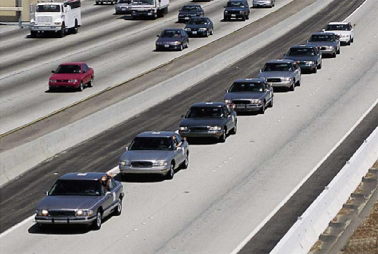
Figure 9.3 Demonstration of an eight sedan platoon.
Source: Photo courtesy of California PATH.
A platoon of vehicles is defined as a train of vehicles moving along a roadway with one lead vehicle, as shown in Figure 9.3. Each vehicle follows the vehicle in front of it maintaining a safe distance. The lead vehicle may have a human driver fully in control and drivers of the vehicles following may be less actively involved in driving. Thus even with only limited ADAS capabilities (sensors to measure distances to preceding vehicles), significant self‐driving capabilities can be achieved in scenarios with highway travel with straight roadways. The addition of lateral control and lane tracking can enable approximately Level 3 self‐driving on highways. Platoon driving also enables more fuel efficiency (due to reduced aerodynamic drag) and can also lead to more efficient traffic flow due to being able to pack vehicles closer together with less likelihood of collisions.
In order to support platoon operations, ACC is extended such that vehicles communicate with each other; in particular the lead vehicle in the platoon provides relevant information to the following vehicles. This is known as cooperative adaptive cruise control (CACC). In this section we briefly describe the history and the current state of the art in CACC‐based vehicle platooning. We describe the key underlying principles and the role 5G communication can play in this technology.
Sensors such as radar and ACC are the key requirements for platooning. ACC performs electronic actuation of the engine and brakes, based on input from radar or other range estimation systems. Each vehicle in a platoon has a controller that takes as inputs information such as the distance to the preceding vehicle, own speed and acceleration, preceding vehicle's speed, acceleration and intended action, and lead vehicle's speed and acceleration.
Platooning has been the subject of study for several decades from a theoretical standpoint in the automotive community. More recently, there have been various trials that use the ideas that have been developed to demonstrate practical platooning approaches. The work in [14] describes an ACC system that uses a safety distance separation rule between vehicles that increases vehicle throughput without causing oscillations in inter‐vehicle spacings. In [15], the authors report results of one of the first systematic studies of platoon behavior by using a nonlinear simulation model and described the design of a control system for platoons.
There have been many trial activities focused on platooning. The trucking industry in particular has substantial interest in platooning technologies as it can enable fuel savings due to reduced aerodynamic drag for the following vehicles (in addition to all the other advantages of platooning) [16]. Major truck manufacturers are engaged in demonstration of on‐highway truck platooning (for example see [17]).
9.4.1 Platoon Model
A mathematical model is provided below for describing a CACC‐based platoon, and is illustrated in Figure 9.4. ![]() denotes the length of each vehicle, vi denotes the velocity of the ith vehicle in the platoon and gi denotes the spacing between the ith vehicle and the (i − 1)th vehicle. A vehicle follows a preceding vehicle in the platoon at a constant time headway. The time headway represents the duration the vehicle would take to cover a distance at its present speed. It captures the intuitive notion that the gap should be larger at higher speeds to accommodate longer stopping distances at higher speeds. That is, the desired inter‐vehicle gap for the ith vehicle gdes,i is defined in terms of a constant time headway h and the current velocity:
denotes the length of each vehicle, vi denotes the velocity of the ith vehicle in the platoon and gi denotes the spacing between the ith vehicle and the (i − 1)th vehicle. A vehicle follows a preceding vehicle in the platoon at a constant time headway. The time headway represents the duration the vehicle would take to cover a distance at its present speed. It captures the intuitive notion that the gap should be larger at higher speeds to accommodate longer stopping distances at higher speeds. That is, the desired inter‐vehicle gap for the ith vehicle gdes,i is defined in terms of a constant time headway h and the current velocity:
Figure 9.4 Platoon system parameters.

Figure 9.5 Vehicle response modeling.
where gmin denotes a minimum gap. The gap error with respect to the preceding vehicle is ei(t) = gi(t) − gdes,i(t).
Vehicles respond to acceleration and deceleration commands with a time lag. This is modeled as in the following. The external input to the engine (i.e. the desired acceleration) and the actual acceleration are related as follows:
where ui is the desired acceleration of the ith vehicle, ai is the acceleration of the ith vehicle, ![]() is the derivative of the acceleration of the ith vehicle, and τ is a constant representing engine dynamics. Additionally, vehicles can have a time delay φ before responding to the input command. Thus the vehicle response can be represented as:
is the derivative of the acceleration of the ith vehicle, and τ is a constant representing engine dynamics. Additionally, vehicles can have a time delay φ before responding to the input command. Thus the vehicle response can be represented as:
where φ is a time delay before the vehicle response to the command begins.
Figure 9.5 illustrates the vehicle response to an application of a step input increasing acceleration by 2 m/s2, for different values of τ and φ. Larger vehicles have a larger value of the time lag constant τ, which results in a longer time to achieve the desired acceleration.
The controller at each vehicle tries to drive the gap error to zero by applying acceleration or deceleration commands. We illustrate below mathematically how the gap error is minimized utilizing information from the preceding vehicle [15, 18]. Note that ![]() and
and ![]() , where li(t) is the location of the ith vehicle at time t. We write the gap error and its derivatives as follows:
, where li(t) is the location of the ith vehicle at time t. We write the gap error and its derivatives as follows:
From Eq. (9.3) we have ![]() . Substituting this into Eq. (9.6) yields:
. Substituting this into Eq. (9.6) yields:
Taking the next derivative of ei(t) and simplifying we have:
where ∁i = hui(t − φ) + ui(t − φ) represents the action taken by the ith vehicle. Note the dependence of ![]() on ui − 1 (the desired acceleration at the (i − 1)th vehicle). This is due to dependence of the gap error derivatives on ai − 1 (acceleration at the (i − 1)th vehicle). ∁i can be viewed as correcting for the observed gap errors and the observed result of the control input ui − 1 to the preceding vehicle.
on ui − 1 (the desired acceleration at the (i − 1)th vehicle). This is due to dependence of the gap error derivatives on ai − 1 (acceleration at the (i − 1)th vehicle). ∁i can be viewed as correcting for the observed gap errors and the observed result of the control input ui − 1 to the preceding vehicle.
A standard PID controller is assumed and a control law is chosen as follows [19]:
where k1, k2, and k3 are constants. The action performed by the preceding vehicle ui − 1 is received in a message from the preceding vehicle. It is assumed here that the delay in receiving the message from the preceding vehicle is negligible; in general a communication delay of θ can be reflected in Eq. (9.9) by replacing ui − 1(t) with ui − 1(t − θ).
Using a vector ![]() to represent the gap error and its derivatives, the following closed loop system is obtained:
to represent the gap error and its derivatives, the following closed loop system is obtained:


Figure 9.6 Inter‐vehicle gaps with ACC.

Figure 9.7 (a) Speed and (b) gap for vehicles 2, 5, 10, and 15 in a platoon at 30 m/s average speed and 13.33 Hz message rate (1 represents lead vehicle) [20].
The above closed loop system enables the ith vehicle to compute and apply the desired action to minimize the gap error; that is ![]() .
.
Figures 9.6 and 9.7 compare the simulated gap performance of ACC‐based platoons with CACC‐based platoons. The model for ACC is obtained by setting the ui − 1 term in Eq. (9.9) to zero (representing the absence of information about the action taken by the preceding vehicle). The scenario consists of a lead vehicle with a sinusoidally time‐varying speed with an average speed of 20 m/s, followed by nine vehicles in the platoon. A time headway h = 0.5 s, minimum gap g0 = 2 m and [k1 k2 k3] = [0.2 0.7 0] are assumed. As can be seen from Figure 9.6, the inter‐vehicle gaps increase rapidly toward the back of the platoon, clearly demonstrating an instability in the system.
Figures 9.7 and 9.8 ([20]) show the simulated performance of a CACC‐based platoon. The scenario consists of long platoons of 15 vehicles on a 4‐lane highway. A time headway of 0.5 s is assumed. Messages are transmitted through a base station and a communication delay of up to 100 ms is assumed (in line with Long‐Term Evolution [LTE] network communication). All vehicles transmit 300 byte messages 13.33 times per second, with the platoon moving at an average speed of 30 m/s. The bandwidth supported by LTE limits the number of vehicles. At an average platoon speed of 30 m/s, approximately 312 vehicles are associated with a base station and a message rate of 13.33 Hz can be supported. Figure 9.7 shows the speeds and gaps of the vehicles for the 30 m/s case. As the speed decreases, the vehicle density increases. At an average platoon speed of 5 m/s, approximately 870 vehicles are associated with a base station and the message rate that can be supported falls to 5 Hz. Figure 9.8 shows the speeds and gaps of the vehicles for the 5 m/s case. Although in both cases the gaps are within safe limits, the second case shows larger variations of speeds and gaps of following vehicles compared with the lead vehicle.
Figure 9.8 (a) Speed and (b) gap for vehicles 2, 5, 10, and 15 in a platoon at 5 m/s average speed and 5 Hz message rate (1 represents lead vehicle) [20].
The LTE bandwidth also limits the sizes of messages transmitted by the vehicles. The 300 byte size assumed above corresponds to a relatively simple Basic Safety Message. If additional information is transmitted (e.g. vehicle information, sensor data, etc.), the message sizes can be much larger. This then limits the message rates, which in turn affects the platoon performance.
Figure 9.9 Comparison of jerk at the 11th vehicle in a platoon at 1 and 10% message error rates [20].
Reliability of the communication has an impact on passenger comfort. One of the measures of passenger comfort is the derivative of the acceleration, also known as jerk. Figure 9.9 ([20]) shows that higher message error rates can significantly increase jerk and result in passenger discomfort. Furthermore, there is a need to have very short time headways for truck platooning, to minimize aerodynamic drag and maximize fuel efficiency. While LTE can support reliable communication mainly by using techniques such as more repetitions or higher transmit power, such techniques come at the expense of resource efficiency and as a result limit the number of vehicles that can be supported.
While achieving small or zero gap errors is the main underlying principle in CACC‐based platooning, there are many other challenges to safe platoon operation:
- Lateral control: In addition to the longitudinal control described above, it is necessary to have lateral control such that vehicles stay in lane and follow curved roadways in a platoon.
- Vehicle dynamics and actuation delays: Mechanical responses have time delays and typically exhibit nonlinear behavior. Furthermore, mechanical characteristics of vehicles can change over time.
- Responding to abrupt braking and stops: Given different braking capabilities of vehicles, abrupt speed reductions of vehicles in the platoon can pose a danger to following vehicles.
- Minimizing jerks: Depending on the speed and actions taken by vehicles in the platoon, a vehicle can experience rapid switching between acceleration and deceleration, which can cause passenger discomfort. To ensure passenger comfort, jerk should be kept within approximately 0.1–0.2 g/s (where g is the acceleration due to gravity).
- Optimizing gaps to maximize vehicle throughput and safety: The time headway may need to be adjusted based on speed and traffic conditions.
- Adapting to “cut‐in” and “cut‐out” vehicles: Vehicles may abruptly cut into the gaps in a platoon or abruptly leave a platoon. The vehicles in the platoon have to be able to respond to such situations without compromising safety or passenger comfort.
- Platoon formation and admission control: Well defined procedures and communication protocols are needed for advertising the existence of a platoon, obtaining relevant information about a platoon, and joining and leaving a platoon.
The controller in the CACC model described above uses information from only the immediately preceding vehicle. This can be extended to use the information from the lead vehicle of the platoon [19, 20] and other vehicles in the platoon, to improve performance.
All of these requirements suggest a need for a more robust communication system than the currently deployed cellular technologies, in order to support efficient and large scale platooning. The following main features of 5G NR (New Radio) enable it to overcome the limitations of LTE and support platooning applications more efficiently.
- Cell capacity and spectral efficiency: NR supports much wider bandwidths than LTE (up to 400 MHz). Additionally, multiple‐input multiple‐output enhancements lead to at least a doubling of spectral efficiency even in sub‐6 GHz deployments. Use of LDPC coding for the data channels also improves spectral efficiency. As a result, NR can support significantly more vehicles per cell site.
- Reliability: NR has been designed to be able to support ultra‐reliable communication. In particular, the NR control channel uses Polar codes to improve reliability of the control channels. NR also supports various other techniques to improve reliability. These include repetitions of transmissions, improved CSI reporting and packet duplication at the PDCP layer. Studies indicate that, with these enhancements, NR can achieve reliability of 99.999% or higher [21].
- Latency: While the CACC performance is not very sensitive to latency (e.g. in the analyses above, a latency of 100 ms was assumed), various other aspects of platooning benefit from low latency. For example, lower latency communication helps in cases of abrupt braking and cut in of vehicles described above. Furthermore, lower latency also makes it easier to achieve platoon stability. NR achieves a latency of 4 ms (one way, between the device and the base station). This is further reduced to 1 ms if mini‐slots are used.
In addition to the above, mobile edge computing is a key feature of 5G. It not only enables a reduction of delays in the communication path for applications but also enables other applications which rely on localized information. These aspects are discussed next.
9.4.2 Edge Computing for Platooning
While the CACC approach described above forms the core of platooning, there are several other features needed for successful and widespread platoon operation. Examples of such features include being able to handle vehicles of different types (e.g. a large vehicle following a smaller vehicle), adapting to weather and traffic conditions, managing merging and exiting vehicles, etc. The edge computing capabilities of 5G can be leveraged to support such features and significantly improve platoon operation.
Roadside base stations (Roadside Units [RSUs]) can provide 5G connectivity to vehicles. All intelligence related to platooning can reside in a platooning server that is connected to the RSUs, as shown in Figure 9.10. Vehicles communicate relevant information to the platooning server, which then acts on the received information and transmits commands to the vehicles.
The platooning server can enable functions well beyond CACC, as described below:
- Core platooning functions: Vehicles periodically report their speed, target acceleration, and observed inter‐vehicle gap with respect to the preceding vehicle. For each vehicle, the platoon server uses information from the preceding vehicle and the platoon leader to determine a command (i.e. an adjustment to acceleration/deceleration) and communicates this command to the vehicle. The platoon server can also utilize information from other intermediate vehicles in addition to the lead vehicle and the preceding vehicle. It is noteworthy that the platoon server can maintain two control loops for each vehicle – one with respect to the preceding vehicle and the other with respect to the lead vehicle – and transmit a command to the vehicle based on the “safer” of the two. A vehicle performing such control by itself would not be able to do this since it would not have an estimate of the distance to the lead vehicle (sensing is limited to the preceding vehicle). The platoon server on the other hand collects information from all vehicles and is able to estimate, for each vehicle, the gap with respect to the lead vehicle.

Figure 9.10 Edge computing for platoons.
- Platooning functions customized to vehicles: Larger and heavier vehicles generally require longer durations to accelerate to a target speed or to brake. This impacts the safety of heterogeneous platoons. This can be handled by the platooning server by customizing the platoon control and commands for each vehicle. For example, for larger vehicles a larger value of engine time lag τ may be used. Similarly, for larger vehicles the time headway to the preceding vehicle can be larger. Vehicles report the relevant information such as weight, number of axles, etc. before the platoon establishment. In addition, vehicle diagnostic information can be made available to the platoon server to account for situations where some essential functions may not be functioning optimally.
- Taking into account location specific information: Although highways are designed for uniformity, there are significant variations in terrain and topography even over a few miles. Knowledge of the topography can improve the platooning performance by adjusting target speeds and accelerations. Additionally knowledge of upcoming curves in the roadway can help assist lateral control. The information about the topography and the roadway can easily be pre‐provisioned into the server with location coordinates. It is impractical to pre‐provision such information in a vehicle, since it is not possible to know in advance where the vehicle is going to travel.
- Taking into account traffic/incident information and weather information: Traffic information is generally available today through crowdsourced platforms and can provide advance knowledge of traffic incidents and congestion. Incorporating such information into the platoon server enables better routing and management of the platoon. For example, in heavy traffic, the platoon may be broken up into smaller platoons or entirely disbanded. Weather conditions can affect performance of vehicles in different ways. Knowledge of weather conditions can enable adaptation of platooning procedures to ensure safer travel. In addition, real‐time information from vehicles, such as wheel slippage, can be used to guide following vehicles.
- Managing of vehicles entering and leaving a platoon: Vehicles leaving or joining a platoon can disrupt the platoon structure and if the disruption is not quickly controlled, the platoon can disintegrate. While a vehicle leaving or joining the platoon is recognized by the vehicle immediately following (via its sensors), relying on the sensors alone can result in dramatic and uncomfortable changes to speed. Instead, a platoon server can create a large enough gap for a vehicle joining the platoon to smoothly join the platoon and smoothly close the gap when a vehicle leaves the platoon.
- Platoon establishment and dissolving: A well‐established protocol for establishing and dissolving a platoon is an essential requirement for platoon operations. Such a protocol has to not only establish the sequence of vehicles but also needs to have means to authenticate vehicles. A rogue driver/vehicle that is able to join or lead a platoon can cause serious damage. The security and authentication capabilities that cellular networks are known for can be used to ensure that rogue actors cannot take control of platoons.
9.5 High Definition Maps Use Case
An HD map is a machine‐readable map which allows an automated vehicle to know where it is and what is around it. This type of map comprises various tiled layers that are highly accurate (centimeter level accuracy). Each tile contains a section of a map that covers a given geographical area. Utilizing the concept of tiles has several advantages because it allows the procedures related to map updates to be optimized. Instead of the vehicle having to download entire maps, individual tiles of interest can be provided to the vehicle, allowing for optimization in terms of latency and bandwidth requirements during map downloading and map updating procedures. The tiles of interest for a given vehicle usually depend on the vehicle location and the vehicle route. If a route is known or can be predicted, then only the tiles in and around the route need to be provided to the vehicle. Moreover, when changes occur in the environment (such as new roads added), only the tiles of interest are affected and only those need to be updated in the vehicle.
A typical configuration with the main components that may be involved in this use case are depicted in Figure 9.11.
The components shown in the figure contain three different applications of the HD maps:
- HD map client application: The HD map client application is installed in the vehicle. This application is responsible for maintaining the most up‐to‐date map of the surroundings. It uses stored information (e.g. a reference map), information collected by the vehicle sensors, and information received from other vehicles and/or the network in order to update the HD map.
Figure 9.11 Generic HD maps use case main components.
- HD map edge application: The HD map edge application is installed in the edge cloud platform, which is also referred to as the MEC platform, which was discussed in Section 9.3. This application handles localized information and is responsible for updating the information in vehicles located in a given geographical area. The geographical area of interest may be predefined and fixed, or it may dynamically change. The HD map edge application communicates directly with the HD map client and HD map central applications.
- HD map central application: The HD map central application is responsible for the large scale aggregation of information and modification of large scale maps. This application is aware of all of the HD map edge applications running in the different edge cloud platforms, and their respective geographical area of interest. This application is responsible for configuring the relationship between the HD map edge applications and their geographical area of interest.
As previously discussed, by placing content in the MEC platform, the user can access the content much faster, and without increasing the bandwidth requirements toward the backend cloud. As a result, more users can be supported in the network. In addition, applications can have access not only to local content but also to real‐time information related to the network conditions.
9.5.1 HD Maps Procedures
Typical procedures involved with HD maps are map downloads and map updates. Here we provide an overview of how these procedures are usually implemented and how they are usually partitioned between the vehicle, the edge platform, and the backend (cloud) platform.
9.5.1.1 Map Download Procedure
When the vehicle first requests a map of a given area, it determines its current location and then sends the request to the HD map edge application at the edge cloud platform, with the current location included in the request. Requests for maps also include the time stamp of when the map was last updated, so the network only needs to send the changes since the last update. Based on the location, the HD map edge application determines the tiles that need to be provided. The total number of tiles to be provided is usually determined by the HD map edge application at the edge cloud platform. Typically, a few tiles corresponding to the area around the vehicle need to be provided. If the vehicle route is known and provided to the edge application, then tiles in and around the route may also be provided to the vehicle.
If the edge cloud server does not have all tiles of interest, it may request them from the HD map central in the backend cloud platform. Once the tiles of interest are received from the backend cloud server, they are provided by the edge cloud server to the vehicle. As the vehicle moves, new tiles may be requested.
The map download procedure is depicted in Figure 9.12.
Figure 9.13 shows a typical data flow for the HD map download procedure in more detail. The Sensor Data Processing function receives information gathered by the sensors and processes it in order to deliver processed information to other functions. This function also determines the vehicle location based on the sensor information. With the location information available, the Vehicle Tile Handler function checks for maps that are stored and determines if tiles corresponding to the location are available. If the required tiles are not available, a request for the tiles is sent to the Vehicle Request Handler function to forward the request to the edge.
The Edge Request Handler function receives the request and forwards to the Security Manager function, which authenticates the client and authorizes the transaction. The Edge Tile Handler will then process the request. If a request for map tiles is received, it uses the location and time stamp provided in the request and determines which tiles to send. If the tiles are available locally, then it sends the tiles to the client application. If the tiles are not available locally, it sends a request for the tiles to the HD map central application at the backend cloud platform.
Figure 9.12 HD map download procedure.
At the backend cloud server, the Cloud Tile Handler uses the location and time stamp provided in the request to determine which tiles to send.
9.5.1.2 Map Update Procedure
The other procedure of interest is the one where a change in the surroundings is reported by vehicle and the map is updated. In this process, a sensor‐equipped vehicle compares the map that was acquired from the edge cloud server to its own observation of the environment (via sensors) and determines deviations with significant size. For example, a vehicle may observe via its sensors the presence of a roadside barrier that is not present in the HD map currently stored. The deviations are then sent to the HD map edge application at the edge cloud platform. The HD map edge application then evaluates and integrates this information. The independent observation (from independent vehicles) of this deviating region enables the edge cloud server to increase the confidence and accuracy of the spatial change on the map. Once such a spatial change has been reflected into the local map stored in the edge cloud server, then a propagation to the backend server shall follow in a regular update time slot. Once new information is provided to the backend server, the HD map central application is responsible for distributing the new information to a relevant area.

Figure 9.13 HD maps application data flow during map download.
The update map procedure is illustrated in Figure 9.14, where vehicle 1 observes the changes in the environment via its sensors, and reports the differences to the HD map edge application. Note that in this example vehicle 2 is not equipped with the same sensors but it still learns about the changes in the environment via information exchanged between the vehicles (through the network).
Figure 9.15 shows a typical data flow for the HD map update procedure in more detail. A reference map is assumed available in the vehicle (i.e. previously uploaded to the application in the vehicle). The Sensor Data Processing function receives information gathered by the sensors and processes it in order to deliver processed information to other functions. The captured and processed data is provided to the Map Comparator and Aggregator function, which compares the stored environment information with that captured by Sensor Data Processing. When a map deviation is detected, this function aggregates the map deviations with existing tiles to make a new updated reference map.
The Vehicle Tile Handler function is continuously performing tile acquisition as the vehicle moves and is the one that decides when the map deviation needs to be sent to the network for an update. This decision may be based on the dynamic nature of the information: the vehicle may be configured to only report static/structural changes, such as new roads and buildings, as opposed to for example reporting the presence of a road construction barrier, which is temporary.
Once the vehicle sends the information to the edge cloud server, the Edge Request Handler function receives the message and forwards it to the Security Manager function, which authenticates the client and authorizes the transaction. The Agent Consensus Manager decides if the detection of the deviating region gives enough confidence. These updates are usually decided based on crowdsourcing, which means that the Agent Consensus Manager may wait for several reports of the same deviating region from different vehicles in order to establish consensus. If consensus is reached, then the deviation is sent to the HD map central application in order to update the global database. The edge cloud server may also send the deviation to other vehicles in the region it is serving.
The Cloud Tile Handler function receives the updated map/tile and decides if the changes are to be incorporated and if so, modifies and stores the updated tiles. The Cloud Tile Handler function also decides if the information needs to be sent to other edge cloud servers, based on the tile location and geographical responsibility of each HD map edge.

Figure 9.14 HD map update procedure.
9.5.2 Edge Computing for HD Maps
As discussed in the previous sections, by having a differentiated and hierarchical level of responsibility between the edge platform and the backend platform, it is possible to optimize the latency and the bandwidth utilization of the system, maximizing the network capacity. Each edge cloud platform is responsible for a predetermined geographical area. The geographical area may be chosen based on the number of vehicles that need to be supported in the region, the latency requirements for the services supported, and the traffic generated by the users in the given region. A large geographical area minimizes the number of edge servers needed but may impact latency and capacity. A small geographical area provides the optimal latency and capacity, at the cost of more edge servers.
Another benefit of this model is the ability to scale the number of edge servers needed as the number of users to be serviced increases in any given region or as more services get deployed. Initial deployments may assume a single edge platform covering a very large area. As autonomous driving becomes more popular, more servers can be deployed in the same region. This flexibility reduces the initial cost of deployment.
RSUs can be utilized for communication between vehicles and edge servers. RSUs provide wireless connectivity between vehicles and computing devices deployed at the side of the road. Usually these computing devices are targeted toward road traffic optimization. HD maps functionality can be seen as one of such services. It is important to note that the deployment of RSUs is not likely to be ubiquitous and, when not present, base stations (or gNBs) can be utilized for the communication between the vehicle and the edge server.
Figure 9.15 HD maps application data flow during map updates.
Another advantage of utilization of edge computing capabilities for the HD maps use case is that it allows for location services to be incorporated in maps. Traffic and weather information can be displayed in the map to help the driver or can facilitate optimal route selection. Advertisements can be incorporated into the maps, especially if a route is known (e.g. sending coupons for stores that are on the user's route).
The use case for HD maps can be extended to a real‐time situational awareness (RTSA) map. As compared with HD maps, which is the use case to distribute information on relatively slow changing road conditions, a RTSA map distributes real‐time information to traffic participants, including vehicles, bicycles, and pedestrians. Use cases such as a pedestrian crossing a street and bicycle warnings are examples of RTSA map updates. These are notifications sent from RSUs to vehicles regarding the presence of pedestrians crossing the street or bicycle ahead warnings. Such notifications require very stringent requirements on latency and reliability. The URLLC (ultra‐reliable and low‐latency communications) features of 5G‐NR, combined with edge computing, can be used to facilitate such use cases. These use cases would utilize a procedure similar to the map update procedure described in the previous section but without the need of crowdsourcing information. In the RTSA map use case, the Agent Consensus Manager decides on the deviating confidence based on a single report (either from a vehicle or from a local video near an intersection). A single report in this case would be sufficient to reach consensus and other vehicles in the same geographical area can be notified of the presence of a pedestrian or bicycle. In this case, because the changes are temporary, the system may not update the global database. This is yet another advantage of using a MEC platform for this use case: the temporary changes stay confined to the local platform, without impacting the central database. The updates are done in a fast and efficient manner, thus meeting the service requirements without wasting communication, compute and memory resources.
9.6 Summary
The next decade is likely to see major changes in how we operate vehicles and how transportation systems function. Several of these changes are already underway and the general trend of these changes is the automation of various functions in vehicles and the reduction of human involvement in driving. Many of these changes are driven by technological advances in sensing, robotics and applied machine learning.
Sensors have fundamental limitations that relate to range and line‐of‐sight. Radar, lidar, and cameras cannot see past obstructions. Communication has played and will continue to play an important role in making vehicular automation more effective.
One of the key features of 5G is MEC. MEC enables placement of computing and storage resources closer to physical locations where they are needed. Given that much of the information related to driving is geographically local, MEC can provide significant benefits to connected vehicle use cases. It not only enables a reduction in application latency but it also allows for deployment of targeted infrastructure and computing resources specific to the connected vehicle use cases. For example, map information or image recognition capabilities can be placed near roads and can serve vehicles and RSUs.
While we have not discussed all possible use cases in the connected vehicle space, we cover two exemplary use cases. Platooning of vehicles is widely seen as the first step toward significant automation of vehicles on highways, particularly trucks. It has significant benefits in terms of improving safety and reducing driver fatigue, and it also provides significant fuel savings. Platooning is based on CACC which requires a vehicle to receive information from vehicles ahead of it and perform corresponding adjustments to its speed and acceleration. In particular, receiving information periodically about the engine action applied by the preceding vehicle or vehicles enables nearly perfect tracking of vehicles even in very long platoons. If the communication between vehicles is error prone (i.e. messages are lost or delayed), the vehicle occupants can experience discomfort in the form of jerk (which increases with larger proportions of lost messages). The higher reliability of 5G‐NR communication can greatly reduce the possibility of such jerk. Additionally, MEC can enable platooning features that go well beyond the longitudinal control of vehicles and are essential to platoon operation. Examples of such features include support for vehicles cutting‐in and cutting‐out, customized control for different types and sizes of vehicles, and adaptation based on location‐specific information.
HD maps are essential for higher levels of automation of vehicles. HD maps are machine readable maps that enable a vehicle to locate itself within and navigate through its surroundings. They provide information about surroundings at a very fine granularity. Up‐to‐date maps are critical for automated driving. Collection of information for HD maps is done via crowdsourcing and can be supplemented with sensors placed in the vehicle and at RSUs and reported to an edge server. Significant computational and storage capabilities are needed to keep the HD maps up to date. In particular, it is necessary to validate the collected information and aggregate information collected from multiple sources. The information then has to be disseminated to vehicles. The MEC architecture combined with the 5G‐NR low‐latency communication can achieve the timely updates of the maps to vehicles.
Acknowledgment
The HD maps work described in this chapter was greatly assisted by the expertise of Dr.‐Ing. David Gonzalez‐Aguirre.
References
- 1 Commission for Global Road Safety (2006). Make Roads Safe. A New Priority for Sustainable Development.
- 2 Dalal, K., Lin, Z., Gifford, M., and Svanstrom, L. (2013). Economics of global burden of road traffic injuries and their relationship with health system variables. International Journal of Preventive Medicine 4 (12): 1442–1450.
- 3 The Economist (2014). The cost of traffic jams http://www.economist.com/the‐economist‐explains/2014/11/03/the‐cost‐of‐traffic‐jams (accessed 25 January 2019).
- 4 Schneider, B. Traffic's mind‐boggling economic toll http://www.citylab.com/transportation/2018/02/traffics‐mind‐boggling‐economic‐toll/552488 (accessed 25 January 2019).
- 5 Arnott, R. and Small, K. (1994). The economics of traffic congestion. American Scientist 82 (5): 446–455.
- 6 Critical Reasons for Crashes Investigated in the National Motor Vehicle Crash Causation Survey, DOT HS 812 115, February 2015.
- 7 CAR 2 CAR Communication Consortium (2017). Road Safety and Road Efficiency Spectrum Needs in the 5.9 GHz for C‐ITS and Automation Applications, February 2017.
- 8 5G Automotive Association (2016). The Case for Cellular V2X for Safety and Cooperative Driving, November 2016.
- 9 Preliminary Statement of Policy Concerning Automated Vehicles, May 2013.
- 10 MEC in 5G networks, ETSI White Paper No. 28, June 2018. https://www.etsi.org/images/files/ETSIWhitePapers/etsi_wp28_mec_in_5G_FINAL.pdf (accessed June 2019).
- 11 https://www.etsi.org/technologies/multi‐access‐edge‐computing (accessed June 2019).
- 12 Mobile Edge Computing (MEC); End to End Mobility Aspects Group Report, ETSI GR MEC 018 V1.1.1 (2017–10).
- 13 Draft, Multi‐access Edge Computing (MEC); MEC Application Mobility Draft, ETSI GS MEC 0021 V2.0.8 (2019–04).
- 14 Ioannou, P. and Chien, C.C. (1993). Autonomous intelligent cruise control. IEEE Transactions on Vehicular Technology 42 (4): 657–672.
- 15 Shladover, S.E. (1991). Longitudinal control of automotive vehicles in close formation platoons. Journal of Dynamic Systems, Measurement, and Control 113 (2): 231–241.
- 16 Tsugawa, S. (2014). Results and issues of an automated truck platoon within the energy ITS project Proceedings of the. IEEE Intelligent Vehicles Symposium (IV) (June 2014).
- 17 Volvo Trucks successfully demonstrates on‐highway truck platooning in California https://www.volvotrucks.us/news‐and‐stories/press‐releases/2017/march/volvo‐trucks‐successfully‐demonstrates‐on‐highway‐truck‐platooning‐in‐california (accessed 25 January 2019).
- 18 Milanes, V., Shladover, S.E., Spring, J. et al. (2014). Cooperative adaptive cruise control in real traffic situations. IEEE Transactions on Intelligent Transportation Systems 15 (1): 296–305.
- 19 Ploeg, J., Scheepers, B.T.M., van Nunen, E. et al. (2011). Design and experimental evaluation of cooperative adaptive cruise control 14th International IEEE Conference on Intelligent Transportation Systems, Washington, DC, USA (5–7 October 2011).
- 20 Narasimha, M., Desai, V., Calcev, G. et al. (2017). Performance analysis of vehicle platooning using a cellular network Proceedings of the. IEEE Vehicular Technology Conference (September 2017).
- 21 3GPP TR 37.910 (2019). Study on Self Evaluation Towards IMT‐2020 Submission.