7
Edge Cloud: An Essential Component of 5G Networks
Christian Maciocco1 and M. Oğuz Sunay2
1 Intel Corporation, Hillsboro, OR, USA
2 Open Networking Foundation, Menlo Park, CA, USA
Abstract
This chapter first describes the fundamentals of edge cloud with respect to 5G networking and the associated on-going mobile network transformation. It then describes Software defined networking, its evolution from OpenFlow to P4, and network function virtualization and its implications for realizing disaggregated, control plane – user plane separated mobile core. The chapter introduces an open source platform for mobile core, namely Open Mobile Evolved Core, and discusses its evolution path. Next, it describes the disaggregation and software defined control of radio access networks, and describes the rise of white-box hardware for computation, storage, and networking, and how modern networks will take advantage of cloud technologies at the edge to meet the end devices' ever increasing demands. The chapter further provides a description of end-to-end, software defined network slicing, including programmatic slicing of the RAN and provides insights into how network slicing is related to the edge cloud.
Keywords 5G networking; edge cloud deployment options; mobile network transformation; network function virtualization; Open Mobile Evolved Core; servicebased architecture; software defined networking; softwaredefined disaggregated radio access networks whitebox solutions
7.1 Introduction
This chapter is divided into six parts and each part is an attempt to provide readers with an insight into the past, present and the future of networking.
Part I describes the fundamentals of edge cloud with respect to 5G networking and the associated on‐going mobile network transformation.
Part II describes Software defined networking (SDN), its evolution from OpenFlow to P4 [1], and network function virtualization (NFV) [2] and its implications for realizing disaggregated, control plane–user plane separated mobile core. An open source platform for mobile core, namely Open Mobile Evolved Core (OMEC), is introduced and its evolution path is discussed. The section also describes the features of high‐volume‐servers to perform associated packet processing either in bare‐metal or in an orchestrated cloud environment. Challenges on containerization and networking are discussed.
Part III describes the disaggregation and software defined control of radio access networks (RANs). The disaggregation of the base station into radio unit (RU), distributed unit (DU) and central unit (CU) is overviewed. This part also introduces how software defined controllability of base station nodes is possible and introduces the associated architecture.
Part IV describes the rise of white‐box hardware for compute, storage, and networking, and how modern networks will take advantage of cloud technologies at the edge to meet the end devices’ ever increasing demands. This part also provides examples of Open Platforms such as Open Networking Foundation’s (ONF’s) [3] Central Office Re‐Architected as a Datacenter (CORD) [4], Open Networking Automation Platform (ONAP) [5], open radio access network (O‐RAN) [6, 7] and Facebook’s Telecom Infrastructure Project (TIP) [8] and Open 5G NR [9].
Part V attempts to answer the question, “where is the edge?” and provides insights into how operator, over‐the‐top (OTT), and end‐user workloads can be placed in the distributed network cloud paradigm. This part also provides an overview of a demonstration as a concrete example.
Part VI provides a description of end‐to‐end, software defined network slicing, including programmatic slicing of the RAN and provides insights into how network slicing is related to the edge cloud.
Finally, we conclude the chapter with a brief summary.
7.2 Part I: 5G and the Edge Cloud
Cellular communication has been shaping society for the last 40 years. Approximately every 10 years we have a new generation of cellular standards that take us to the next level. Until recently, this evolution has focused on first enabling and then scaling two distinct services: voice and broadband data. The resulting massive explosion of data usage has resulted in a bleak economic reality for telecommunication operators. Their average revenue per user (ARPU) have been steadily declining over the last number of years. This is mainly because the industry is approaching the limits of both consumer value creation and current network capabilities. 5G is being architected to counter this unsustainable progression. For the first time since the inception of cellular communications, voice and broadband data are not the only use cases for which we optimize the cellular network. Two new, additional broad categories for new revenue generation are ultra‐reliable, low latency communications and support for massive Internet of Things (IoT).
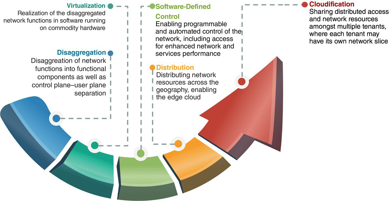
Figure 7.1 Mobile network transformation.
To enable these new use cases a transformation of the network architecture is necessary. Building on the pillars of virtualization, disaggregation, software defined control, and cloud principles over a geographically distributed compute, storage and networking paradigm, this transformation aims to bring the operators agility and economics that are currently enjoyed by cloud providers. The aim is to allow rapid creation of new connectivity services while lowering the necessary capital and operational expenditures. The components of this transformation are summarized below and illustrated in Figure 7.1.
Virtualization: The first step in the network architecture is NFV. With NFV, the traditionally vertically integrated, proprietary realizations of network functions are realized in software to run on commodity hardware.
Disaggregation: Next in the transformation is the disaggregation of the network functions. This disaggregation takes place in two dimensions: functional disaggregation and control plane–user plane disaggregation. While the former paves the way toward microservices‐based, cloud‐native realization of the network functions, the latter enables programmatic, software defined control of access, connectivity, and networking and independent scaling of the user and control planes, an essential feature for efficient resource utilization when different use cases with significantly different requirements share a common infrastructure.
Software defined control: The network architecture transformation requires software defined control so that new access, connectivity and networking services can be rapidly created, and dynamically lifecycle managed. Furthermore, SDN‐based 5G network allows for more efficient network resources management and control using advanced applications that are potentially machine learning driven.
Distribution: A 5G network where infrastructure and resources are shared among different use cases and business verticals require a distributed architecture. Specifically, in addition to access resources, compute, storage and networking resources need to be distributed across the geography so that services that require low latency, high bandwidth and traffic localization can be offered where needed.
Cloudification: The last step in the transformation is cloudification. This is enabled by network slicing and multi‐tenancy. With cloudification, the distributed network resources are allocated to different use cases as well as tenants in an elastic and scalable manner. Further, the utilization of these resources by the use cases and tenants are tracked for monetization.
Let us discuss how this network architecture transformation is taking place. The current mobile network architecture can be illustrated in a simplified form as in Figure 7.2. In this architecture, geographically distributed base stations provide coverage and mobile connectivity for subscribers' user equipment (UE). Traffic from the base stations are aggregated toward centralized operator locations, where vertically integrated, proprietary realizations of mobile core network functions as well as operators' own applications such as VoLTE, texting, and streaming reside. A subset of these locations also acts as the ingress/egress locations for the cellular network toward the Internet toward the public clouds, where the majority of the popular OTT applications reside.
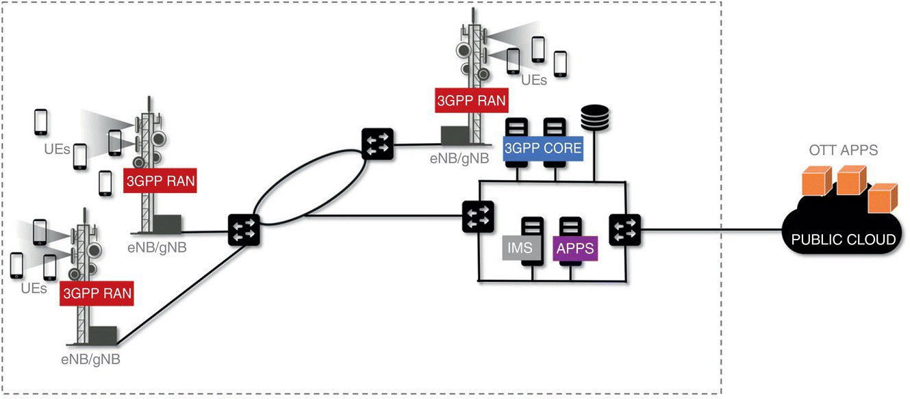
Figure 7.2 Current mobile network architecture.
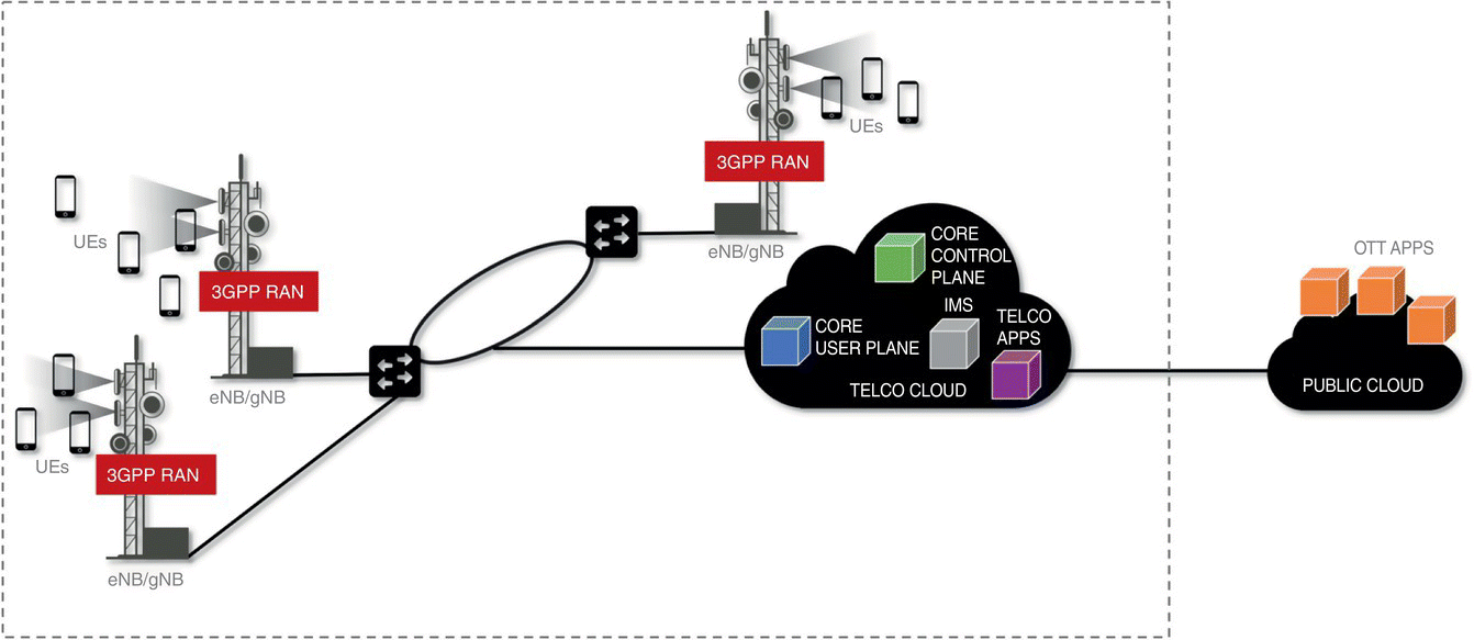
Figure 7.3 First step in transformation of the mobile network architecture: disaggregation and virtualization of network functions.
Toward 5G, the transformation of the network architecture has already started for many of the Tier‐1 operators with virtualization and disaggregation of the network functions that reside in the operators' centralized locations, as illustrated in Figure 7.3. The figure shows the user and control planes of the core as single components for concise illustration – in reality, functional disaggregation is also present for both today and they are composed of multiple components. Virtualization and disaggregation have prompted the transformation of these centralized operator locations effectively into cloud platforms so that the virtualized network function workloads can share the pool of compute, storage and networking resources.
This first step, while beneficial in lowering the operator expenditures when deploying 5G networks, is not sufficient in realizing the different connectivity options necessary to enable new revenue generating business verticals. This requires a distributed network paradigm where edge plays a crucial role.
There are three broad reasons why edge cloud is important. Werner Vogels, the CTO of Amazon, describes these reasons as “laws” because they will continue to hold even as technology improves [10].
The first law is the Law of Physics. The new functions that are to be built toward satisfying the new business verticals usually need to make the most interactive and critical decisions quickly. One example of such a business vertical is Industrial Automation where safety‐critical control requires low latency. If such control were to be realized in the cloud, we know from basic laws that it takes time to send the data generated at the edge to the cloud, and a lot of these services simply do not have the tolerance for this delay. The second law is the Law of Economics. In 2018, for the first time in history, we observed more IoT devices connected to the network than people. These devices are starting to generate a significant amount of data at the edge. The goal is to unlock the value from this data, which is done by processing it. However, the increase in the data generated at the edge is faster than the increase in available backhaul bandwidth. Then, local aggregation, filtering and processing of data at a location close to where it is generated will allow the backhaul networking capacity demand not to grow out of bounds. The third law is the Law of the Land. In some business verticals, such as healthcare, it is required to keep data local and isolated by law. Further, increasingly, more governments impose national data sovereignty restrictions to keep their data localized. Also, some of the business verticals, such as offshore oil rigs, require localized services at remote locations where connectivity to the outside world is not necessary, or is not even possible.

Figure 7.4 Next step in transformation of the mobile network architecture: mobile edge cloud.
A distributed 5G network architecture with edge clouds is illustrated in Figure 7.4. The first benefit the edge cloud brings is that it allows for the virtualization and disaggregation of the base station. Following an O‐RAN architecture [11], we foresee three components: RUs at antenna sites, DUs at cell sites, and CUs that are virtualized and pooling DUs and RUs and are hosted at the edge clouds. Further details of RAN virtualization and disaggregation can be found in Part III. In addition to hosting the CU and thereby enabling RAN virtualization and disaggregation, the edge cloud is also an enabler of low latency, high bandwidth, and localized services. Then, the edge needs to be a place where local traffic break‐outs are enabled. This means, as illustrated in Figure 7.4, the virtualized user plane component(s) of the mobile core network needs to be instantiated at the edge. Toward this end, we also need to host the operator (telco) applications that require low latencies and or traffic localization at the edge. Then, depending on which applications are instantiated at specific edge cloud locations, operators will be able to offer specialized services new business verticals. Via network slicing, multiple such verticals could potentially share the same edge cloud. If the operators are open to having a multi‐tenant edge cloud, OTT applications or components of such applications can also be hosted at the edge, benefitting from close proximity to end‐users and the presence of local‐break outs.
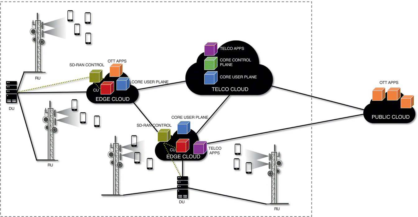
Figure 7.5 Following step in transformation of the mobile network architecture: software defined RAN Control.
We listed software defined control as a fundamental component of the network transformation. An important aspect of this control is the control of the access – the last mile. When such control is employed, the associated controller will be making decisions and controlling the CU and DU components in response to time‐varying RAN characteristics in near real‐time. This necessitates that the associated RAN controller be also instantiated at the edge as illustrated in Figure 7.5.
Cloudification is the elastic and scalable management of a common pool of distributed network resources (access, compute, storage, and networking) so that a common infrastructure may be efficiently and profitably shared among multiple business verticals and tenants and is the last component of the 5G network transformation. Network slicing is an essential enabler for cloudificaton. We briefly describe network slicing in Part VI.
7.3 Part II: Software Defined Networking and Network Function Virtualization
In less than a decade, cloud computing‐based services and applications, enabled by high‐volume‐server’s ability to process networking workloads, increased broadband connectivity and mobile devices or smartphone capabilities, have resulted in many new big data opportunities in different industries. Our daily activities are largely engrained with mail, storage and collaboration tools, music services, photo or video sharing, and social networking, which are available to us wherever we go. Operators see this opportunity to turn cloud‐based approaches to their advantage and implement new architectures that provide network efficiency, quality of experience (QoE), support scalable applications for large number of end‐users and shorten the time‐to‐market for innovative services.
All these are possible thanks to network programmability and a common delivery platform which was introduced by a new architectural approach that leverages the availability of massive compute resources, called SDN. Highly complementary to SDN is NFV which does not necessarily depend on SDN. NFV is an alternative design approach for building complex applications, specifically in the telecommunications industries, by virtualizing different new service functions into building blocks which can be stacked or chained together.
7.3.1 Rise of SDN
Several years ago, a number of university research groups at UC Berkeley and Stanford University started with the idea of separating the control plane from the data plane in computer networking architecture [12]. They experimented with this by disabling the distributed control plane in Ethernet switches and managed the flow of streams through these switches via centralized software control. The SDN approach was claimed to have a quick and reliable deployment of production network, alleviating time‐consuming setup and providing error prone device‐by‐device connection. The OpenFlow specification and later the P4 programming language [13] from ONF were some of several “SDN protocols” that sprang out of this effort.
The control plane in SDN is moved into a high‐powered central computing environment to achieve a centralized view and control of the network. An SDN controller is a middleware software entity which is responsible for the new centralized control plane. It runs the algorithms and procedures to calculate the paths for each flow of packets and communicates this forwarding information to other networking devices. It also supports applications running on top of application programming interfaces (APIs) simultaneously so that the applications can discover and request network resources, either controlled by operations staff or fully automated.
7.3.2 SDN in Data Centers and Networks
In recent years, the rise of virtual machines (VMs) has led to improved server efficiency; however, this has resulted in increased complexity and a huge number of network connections due to the large number of VMs per server. The next step for SDN was to be utilized in data centers. Centralized SDN controllers have created value by analyzing the entire data center network as an abstracted and virtualized representation. These controllers are capable of simulating any network changes ahead of time, and therefore, automatically configuring and preparing different switches when the scenario was activated.
More recently, architects have also been experimenting with SDN in the wide area network. The most well‐known experiment to date is the deployment of central SDN control on Google's G‐scale network [14], as well as custom‐built open switches connecting its data centers around the world. The following benefits were claimed:
- Faster with higher deterministic convergence when compared with the distributed control plane.
- Increased operational efficiency, with links running at 95 versus 25%.
- Fast innovation support through the network simulation in software before production service deployment.
With the advent of SDN and the separation of control and data plane came the opportunity to define, and program, the data plane processing stages of packet forwarding devices, whether implemented in a switch, NIC, FPGA, or CPU. P4 [13] is a domain specific high‐level programming language supporting constructs optimized around packet processing and forwarding for protocol independent switch architecture (PISA). A combination of PISA‐based devices and the P4 language will allow the programmer to achieve device and protocol independence and enable field reconfiguration:
- Device independence: P4 programs are designed to be implementation independent and can be compiled on any targets, e.g. CPUs, FPGAs, switches, etc. The programmer defines the processing that will be performed on the packets as they progress through the various stages of the packet forwarding pipeline.
- Protocol independence: With P4 there is no native support for any protocols as the programmer describes how the incoming packets will be processed through the stages of the PISA device. A device be it a switch, a CPU, or an FPGA is not tied to a specific version of the protocol as the processing for any protocol will be defined programmatically using the P4 language.
- Field reconfiguration: Due to the target device and protocol independence and the abstract language, P4‐based PISA devices can update their behavior as the need to process different fields, different protocol version, or take different actions evolves over time. For example, when a protocol version changes with new and updated field a simple P4 software update taking into account the new fields is developed, recompiled for the specific target device and downloaded to the device enabling field reconfiguration. There is no need to wait for a new spin of the silicon to support a protocol update.
The P4 language is evolving and currently P4_16 [15] is defined as a stable language definition with long‐term support. P4_16 supports ~40 keywords and has the following core abstractions: “Header Types” to define the header's fields, “Parser” to instruct how to parse packet headers, “Tables” containing state associating user‐defined keys with actions for the “Match‐Action” command where “Match” create a lookup key, perform lookup using, e.g. exact match, longest prefix match or ternary match as defined by the user, and then “Action” describing what to do on the packet when a match occurs. “Control Flow” specifies in which order the match‐action will be performed. Then “External Objects” define registers, counters, etc. and “Metadata” defines data structure/information associated with each packet through the processing stages of the PISA‐based device. Figure 7.6 represents a high‐level view of a P4 pipeline on a PISA‐based device.
We can view P4 along with PISA‐based devices as enabling the programmer to do a top‐down approach where the programmer will instruct the device what to do with a packet whereas before P4 and PISA‐based devices it was more of a bottom‐up approach where the devices dictated how the packets would be processed. There are some limitations as the programmer needs to know how many tables in order to perform match/action processing on the packets but P4 and PISA‐based devices enable significantly higher programmability than previously. P4 and PISA‐based devices enable new usage models, e.g. in‐band telemetry on a per packet basis, or performed network functions in the fabric itself.
In Figure 7.7 the communication between the control plane and data plane can be handled using P4 Runtime [15, 16] that can be viewed as an open switch API for control plane software to control the forwarding plane of a packet processing device pipeline, the device either being a programmable switch ASIC, an FPGA, a NIC or a software switch running on an x86 platform. P4 Runtime is agnostic to where the control plane resides, whether on a local switch operating system or on a remote control plane on x86 servers, and solves issues that could not be addressed by previous attempts at defining an open switch API, mainly OpenFlow. Over the last 10 years the industry has learned from experience that OpenFlow suffered from being complex, hard to extend, and ambiguous in its behavior as it only mandates the fields in a packet that should be matched upon but did not always define the actions to be performed on a match leading to different interpretations by different vendors.
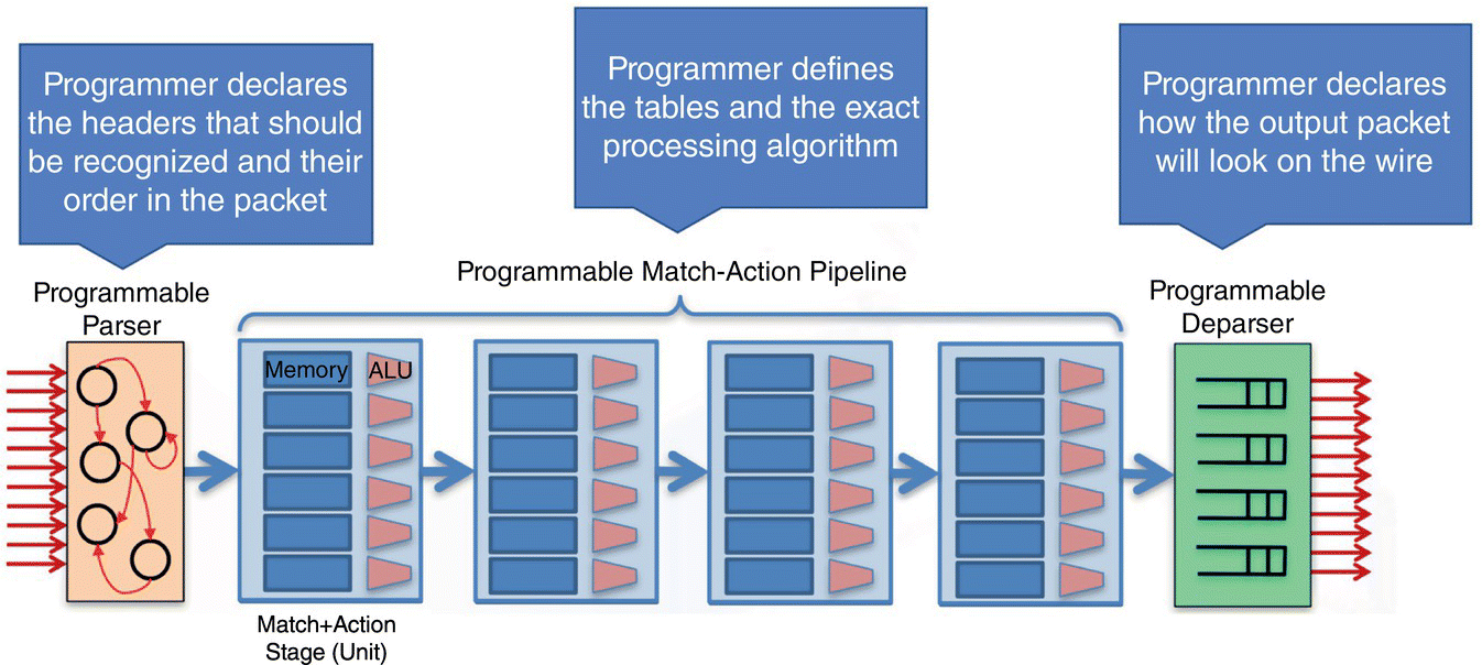
Figure 7.6 PISA architecture and associated P4 pipeline [13].
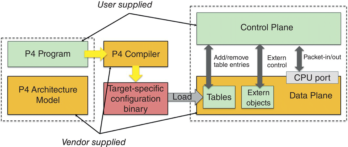
Figure 7.7 P4 workflow [13].
As an example, in Figure 7.7 a P4 program would define the processing pipeline stages of the data plane and the P4 compiler would generate the scheme to be used by the P4 Runtime APIs to add/remove entries in/from the tables at runtime. If the data plane is programmable the developer may extend the P4 program to add new tables to be controlled a runtime, for example to support a new protocol, and the compiler will extend the schema so that the new tables can be controlled through the P4 Runtime API.
7.3.3 Network Function Virtualization
Including the WAN as a component of cloud‐based services and combining the network‐enabled cloud and service providers' SDN capabilities enables the network operators to empower network virtualization and unlock their full potential, including:
- Creating a layered/modular approach to allow innovation at different and independent layers/modules.
- Separating the data plane from the control plane.
- Providing a programmable network through the deployment of a network abstraction layer for easier operation/business application development without understanding the complexity of various networks.
- Providing the capability of creating a real‐time and centralized network weather map.
Operators can now simplify their networks, by removing the complexities of their network topology and service creation, and accelerating the new service process creation and delivery by incorporating NFV.
NFV aims to transform the way that network operators architect networks by implementing the network functions in software that can run on any industry standard high volume server which can be instantiated in any locations in the network as needed, without requiring the installation of new equipment. With NFV the operators' or service providers' deployed equipment can take multiple personalities, e.g. being a router one day, a firewall or other appliance the next.
By network virtualization, the network can be mapped and exposed to logical abstractions instead of a direct representation of the physical network. Therefore, logical topologies can be created to provide a way to abstract hardware and software components from the underlying network elements and to detach control plane from forwarding plane capabilities and support the centralization of control, e.g. SDN. In addition, the network virtualization can be consolidated in computing and storage virtualization to further provide:
- Replicating cloud IT benefits inside their own telecom networks.
- Service velocity and on‐demand provisioning.
- Quicker time to new feature and services driving new revenues.
- Third party apps on deployed infrastructure.
- Operational efficiency.
- Abstract complexity in the network, improved automation and agility.
- Simpler multi‐vendor network provisioning.
- Lower operating expense with unified view (management/control) of multi‐vendor, multilayer.
As the mobile wireless core evolves toward 5G with one of its goals to support edge networking and have a solution available on off‐the‐shelf high volume platforms based on open‐source software a set of partners including operators, software systems providers and merchant silicon providers used operators real 4G/LTE traffic for a detailed performance analysis of the system's components of 4G/LTE wireless mobile core [17] to evaluate the benefits of the architectural changes brought by SDN and disaggregation [18], NFV, as well as Cloud Native operation.
A key goal of this analysis is to understand the impacts of the interaction of control and data plane messages on the Service Gateway (SGW) and Packet Gateway (PGW) of the mobile core, shown in Figure 7.8, to see what benefits disaggregation would bring and how to partition the system to operate in a Cloud Native environment.
A detailed analysis of the interactions between the MME and SGW showed that ~41% of the control plane messages on the S1‐MME interface are forwarded to the SGW's S11 interface [18]. By removing single transaction messages such as “Idle‐to‐Connect” or “Connect‐to‐Idle” the remaining multi‐transaction messages account for 33% of transferred messages from the MME to the SGW. Approximately 18% of these messages are then forwarded from the SGW to the PGW on the S5/S8 interface. These results show that the SGW, which also handles the S1‐U data plane interface is the system's component where control messages processing will have the biggest impact on the data plane processing, especially as the load on the data plane increases. Figure 7.9 shows graphically that 41% of control plane messages impact the SGW data plane.
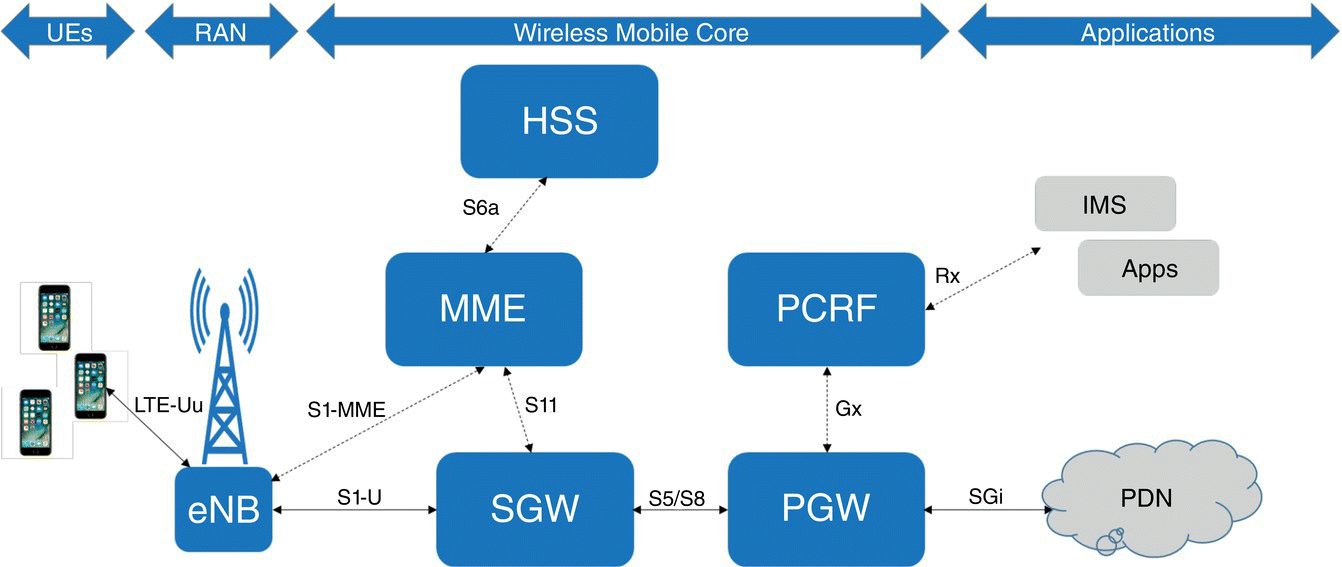
Figure 7.8 Simplified 4G/LTE architecture.

Figure 7.9 Pictorial of control plane message impacts on the data plane in traditional architecture.

Figure 7.10 (a) User plane and (b) control plane queue flooding [17].
The graphs in Figure 7.10 show the linear throughput scalability of the data plane and the non‐linear event rate scalability of the control plane when operating the system in a cluster. In Figure 7.10a the S/P‐GW data plane scales linearly with throughput going from ~5 MPPS with one server node, the thin rectangle on the left‐hand side of the graph, to ~10 MPPS with two servers, the dark rectangle in the middle of the graph, to ~20 MPPS with four server nodes, the white rectangle at the top of the graph. Meanwhile the control plane events processing does not scale linearly as shown in Figure 7.10b. The control plane scales from ~6.5 MPPS on one server, to ~13 MPPS on two servers, the dark rectangle in the middle of the graph. Then, while the simulation shows that we should reach ~26 MPPS using four servers, reaching the top of the black rectangle, we only reach ~16 MPPS using real measurements, the bottom of the black rectangle.
This limitation of control message processing on the current architecture will only become worse moving forward with the expected growth of mobile devices and usages on 5G networks. Some of these usage models will have heavy signaling traffic with limited and sparse data traffic, e.g. IOT Meters while others might be heavy on data traffic, e.g. IOT Security Cameras. To support the growth of devices and usage models, the wireless mobile core needs to scale efficiently, but today's SGW and PGW scale both the control plane and data plane simultaneously. If a usage model only requires scaling, we will have an over‐provisioned data plane or vice versa. This is not the optimal way to adapt system components to traffic requirements as we want to have the component under load scales for what needs to be scaled. For the SGW or PGW we want the control plane to scale independently from the data plane based on usage requirements.
The networking industry is undergoing architectural transformation with SDN principles enabling the disaggregation of the control and data plane [1] as well as efforts in 3GPP defining the Control and User Plane Separation (CUPS) [17] for 5G networks (although CUPS defined for Release 14 could be implemented with 4G/LTE networks). NFV [2] is another transformation enabled by the significant progress made by standard high volume servers to process networking workloads.
Following these architecture principals the virtual EPC SGW and PGW were re‐architected and the resulting implementation is not simply a port of a hardware functionality to a software one running in a bare‐metal process, a VM or a container but instead a carefully thought out architecture, design and implementation to create an efficient and high performance SGW and PGW. Figure 7.11 shows the updated architecture where the SGW and PGW have a data plane following a match/action semantic with optimized data structures enabling fast and efficient lookup of a large number of keys in the millions. Figure 7.11 shows the disaggregated wireless mobile core with the SGW‐C and PGW‐C, the control plane, separated from the SGW‐U and PGW‐U data planes. The reference implementation supports various communication mechanisms between the control plane and data plane, e.g. using OpenFlow v1.3 with a significant number of vendor's specific extensions as OpenFlow has short comings to carry all the necessary information, e.g. as related to billing with this version. A proprietary transport mechanism is also used until the 3GPP CUPS Sxa (SGW‐C to/from SGW‐U), Sxb (PGW‐C to/from PGW‐U) and Sxc (TDF‐C to/from TDF‐U) interfaces are fully ratified.
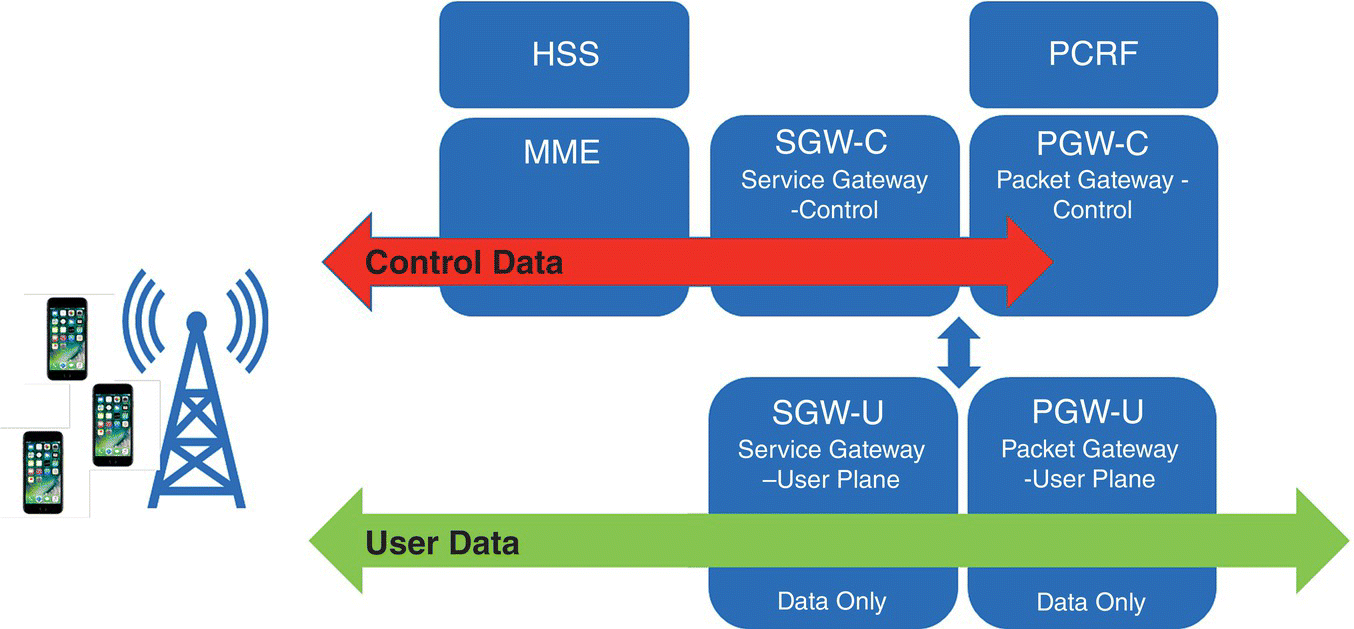
Figure 7.11 Control and data plane separation following 3GPP CUPS architecture.
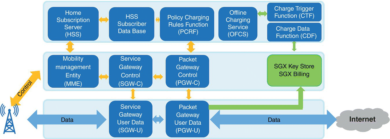
Figure 7.12 Open Mobile Evolved Core.
A reference implementation developed by industry partners called OMEC [19] has been released by ONF and is illustrated in Figure 7.12. Each component of the reference architecture can run as a bare metal process, VM, Docker container orchestrated by Kubernetes or a mix of any of these.
In the OMEC reference implementation, the SGW‐C/U and PGW‐C/U can be configured to operate as a System Architecture Evolution (SAE) Gateway, i.e. with S‐GW and P‐GW functionality.
Open source reference implementations of wireless core in addition to OMEC exist in the mobile ecosystem. Two distinct examples are OpenAirInterface [20] and Facebook Magma [21].
7.4 Evolving Wireless Core, e.g. OMEC, Towards Cloud Native and 5G Service‐Based Architecture
Key promises of NFV were the decoupling of the virtual network function (VNF) from the underlying hardware by moving the functionality from hardware to software environment, e.g. VM, containers, etc. and to enable such VNF to dynamically scale based on workload requirements. This scaling could be scaling‐up or vertical scaling where additional resources like CPU cores, NIC queues, etc. are added/removed to/from the VNF to increase its performance, or scaling‐out or horizontal scaling where instances of the VNF are dynamically instantiated. A combination of vertical and horizontal scaling is also possible where the VNF scales up to a predefined threshold then the system orchestrator based on collected VNF's key performance indicator metrics will launch a new instance of the VNF thus scaling horizontally, migrating the concept of VNF to Cloud native network function (CNF).
As OMEC components run either in bare‐metal, VM or container environment, the next step was to take these components into an orchestrated environment toward being Cloud Native. What does it mean to be Cloud Native? Being Cloud Native has few tenets, among them microservices, containers, continuous integration/continuous delivery (CI/CD), and devops. Micro‐services‐based architecture, usually deployed as containers, is where applications are a collection of loosely connected services where each service can scale independently. Containers package code and its dependencies allowing the applications to run reliably from one environment to another. Containers share a single operating system instance but each one has its own file system and system resources. CI/CD enables continuous integration and development following devops principles of lean and agile development from usually an open source developer community environment, and tests enabling rapid changes and deployment for the VNF.
In the meantime as Cloud Native architecture is taking hold in the cloud and data center industry, 3GPP is defining the upcoming 5G architecture for the wireless core, the 5G service‐based architecture (SBA) where components of this architecture are microservices based, i.e. containers based. Having the wireless core transition to a Cloud Native architecture will enable horizontal scaling of individual components of the 5G SBA control plane, scalability triggered by reaching thresholds set by operators for specific components, e.g. thresholds based on the number of active sessions or loads on specific components. To enable Cloud Native scaling the various components should be stateless, i.e. the particular states of the connection are saved/stored outside of the component itself in distributed database or key/value store, also providing a fault‐tolerant and fault‐recovery mechanism service. The 4G/LTE Release 14 architecture defining CUPS does not lend itself well to be Cloud Native without a major restructuring of the architecture and software which has been addressed with the 5G SBA.
The OMEC reference implementation will evolve toward a Cloud Native architecture over time as it transitions toward a 5G Core network as shown in Figure 7.13 with a subset of 3GPP SBA interfaces.
To deploy and operate a Cloud Native solution we need an orchestrator to manage the lifecycle and run‐time operation of the various containers/microservices. Kubernetes (K8s) [22] is an open source orchestrator for automated deployment and lifecycle management of PODs/containers. A POD in a K8s environment has one or more containers, tightly coupled from an application point of view, sharing resources, and representing the unit of scheduling for the K8s scheduler. K8s recognizes and provides services, e.g. Domain Name System (DNS), to a single POD network interface created using an abstraction called Container Network Interface (CNI). Multiple CNI plugins exist in the industry and among them some enable support of multiple network interfaces, e.g. Multus [23], as the S‐GW and P‐GW components are using multiple network interfaces (S1U, SGi, Control Plane). A key issue with multiple network interfaces is to discover these interfaces network address information, as K8s only knows one POD network address. To enable service discovery for networks/interfaces not known to K8s and managed by K8s we use a key/value store service, e.g. Consul [24]. Over time K8s will evolve and maybe natively support multiple network interfaces per POD.

Figure 7.13 OMEC evolution toward 5G Core (subset of interfaces shown).
Figure 7.14 shows two K8s PODs, each with a single container for control and data plane functionality in a single node, but could be in separate nodes as well. The control plane just uses one interface eth0, known to K8s and for which K8s provides DNS and other services. The data plane uses three network interfaces, eth0 recognized by K8s and S1U and SGi ones whose IP addresses must be registered, discovered, and managed through a database/key value service, e.g. through Consul. The figure also shows the use of the SR‐IOV CNI plugin in order to support SR‐IOV to transfer the data directly from the NIC device into the container networking stack. An alternate solution is to have a single network interface where in the data plane case the traffic on the S1U and SGi interfaces would be demultiplexed in software thus exposing just one interface managed by K8s.
To achieve high performance while the VNFs operate in an orchestrated containers environment the system needs to be tuned for performance. Intel published a white paper on Enhanced Platform Awareness [26] in K8s. Critical system configuration is required to achieve high performance, among them (i) VNF pinning to a specific CPU core, (ii) using huge memory pages, and (iii) single root input/output virtualization (SR‐IOV) for I/O:
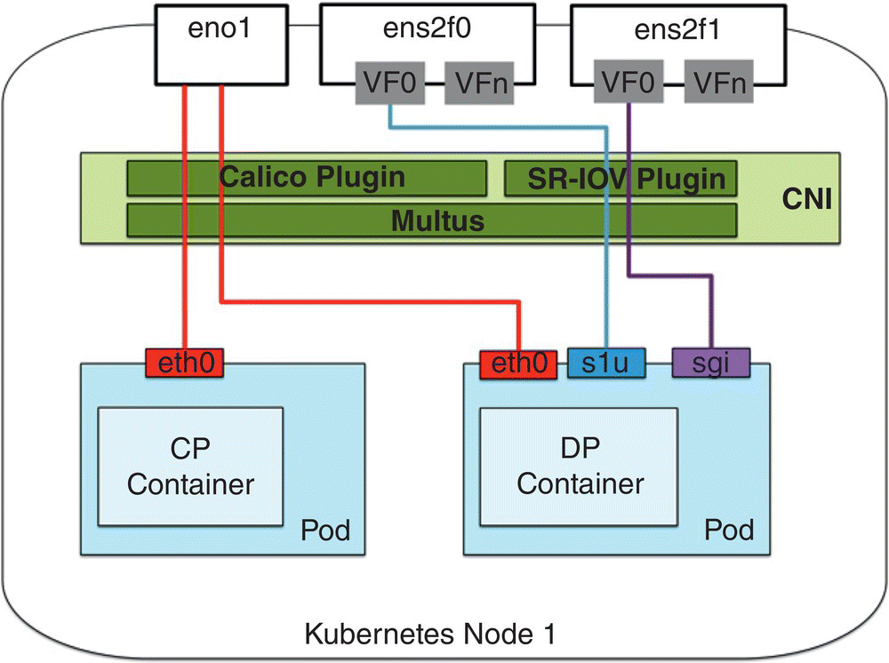
Figure 7.14 Kubernetes and S/P‐GW C and U networking [25].
- The VNFs need to be pinned to one or more CPU core(s) and these cores need to be isolated from the operating system so no other tasks than the VNFs processing are scheduled on these cores. Kubernetes offers a native CPU manager allowing the user to specify the resources, e.g. CPU core(s), memory, etc. dedicated to each POD. The user can specify the POD QoS class as Guaranteed, which guarantee an isolated deployment where the POD is the only scheduled resource on the specified CPU core.
- Huge pages are a large area of memory, e.g. 1 GB, compared with traditional memory page size of 4 kb. For optimal performance DPDK‐based VNFs allocate memory for packet descriptors and buffer from huge pages. When using huge pages, fewer memory pages are needed thus reducing the number of TLB (Translation Lookaside Buffer) misses when a memory page is not found in the cache. K8s supports the allocation of huge pages by application in a POD.
- SR‐IOV for VNFs requiring high‐throughput, low latency I/O. A NIC supporting SR‐IOV exposes independent virtual functions (VFs) for a physical function (PF), i.e. the physical interface and its control of the device. VFs can be configured independently with their own virtual MAC address and IP address. K8s SR‐IOV support is implemented as a CNI plugin attaching the VF to the POD, thus transferring the Rx/Tx data directly from the POD to the device enabling the POD to achieve throughput performance near native bare metal process.
Table 7.1 Performance achieved by a user‐space DPDK‐based application [25].
| Test | Usr Sp Drv | Pinning | Huge | Packets/sa | (with noise) |
| Native | Yes | Yes | Yes | 1550K | (1100K) |
| Kubernetes | Yes | Yes | Yes | 1450K | (1150K) |
| Kubernetes | No | Yes | Yes | 750K | (650K) |
| Kubernetes | Yes | No | Yes | 1450K | 400K |
| Kubernetes | Yes | Yes | No | 1200K | (1100K) |
a 50K Granularity (1 CPU Core).
Table 7.1 shows the performance achieved by a user‐space DPDK‐based application (Usr Sp Drv) versus a non‐user space one as well as the impact the optimizations mentioned above have on the overall throughput performance. As we can see, native versus K8s with all optimizations turned on achieves fairly similar performance, while not pinning a VNF to a CPU core and isolating the core from the operating system can drastically reduce this performance in the presence of “noise,” e.g. another process/VNF being scheduled on the same core.
7.4.1 High Volume Servers' Software and Hardware Optimization for Packet Processing
7.4.1.1 Data Plane Development Kit [27]
To achieve the best possible data plane performance in terms of throughput, latency and jitter the S/PGW‐U data plane functionality is implemented using the Data Plane Development Kit (DPDK). DPDK provides a highly efficient and high performance user mode I/O library bypassing the kernel network stack, thus allowing a very high throughput per CPU Core. As an example from the DPDK Performance Report [28], we see in Figure 7.15 the throughput achieving 50 Gbps line rate at 64 byte packets with an Intel® Xeon® Processor Platinum 8180 (38.5 M Cache, 2.50 GHz) using 2‐core, 2‐thread, 2‐queue per port using the XXV710‐DA2 NIC adapter.
Figure 7.16 gives internal details of the S/PGW‐U data plane functionality where each individual block of the processing pipeline follows a match/action semantic, with a lookup on tunnel end‐point ID, IP address or other identifiers looking for a match and then a specific action depending on the processing block.
To accommodate performance requirements, this data plane can scale‐up with the addition of CPU cores associated with the running instance. For example, a software load balancer can front the data plane pipeline, read data from the NIC, and perform flow‐based load balancing to the CPU cores. Or the data plane pipeline can take advantage of the NIC's supporting multiple Rx/Tx queues and using Receive Side Scaling (RSS) [29] to assign such queues to CPU Cores. As the incoming traffic on the S1‐U interface from the eNB to the S‐GW is encapsulated in a GPRS Tunneling Protocol User Plane [30] frame, then in order to have a large number of entries for an efficient RSS, the RSS key should be on the inner IP address in the tunnel, i.e. the user‐element IP address instead of the external IP address of the tunnel, the eNB IP address. Latest NIC from Intel supports Dynamic Device Personalization [31], allowing the programmer to setup the RSS keys on any field of the incoming payload, which in this case includes performing the hash on the user‐element IP address. This is not an issue on the SGi interface of the P‐GW facing the Internet as the traffic is IP‐based on this interface. If operating in a virtual environment a NIC supporting SR‐IOV [32] offers a single PCIe interface supporting multiple VFs to different VMs or containers.

Figure 7.15 DPDK L3fwd performance.

Figure 7.16 Example of OMEC data plane.
Having a match/action processing pipeline requires a very efficient lookup mechanism which does not degrade the throughput performance as the number of entries in the lookup table grows to millions.
7.4.1.2 Flow Classification Bottleneck
Flow Classification is a common stage for many network functions, and microservices. A common task for the processing stages shown above is Flow Classification. Flow Classification is mainly given an input packet, some identifiers are extracted (e.g. header information) and using these identifiers a flow table is indexed and a certain action is determined based on the lookup result. For example, determining the output port for a packet, or determining an action (e.g. drop, forward, etc.) for a flow, or an address translation table to determine a tunneling ID to encapsulate the packet with. Since Flow Classification needs to be done at line rate, it is typically a performance bottleneck and many specialized network appliances use ternary content addressable memory and hardware accelerated classifiers to optimize this stage.
The three main performance metrics for a flow table design are:
- Higher lookup rate, as this translates into better throughput and latency.
- Higher insert rate, as this translates into faster updates for the flow table.
- Efficient table utilization, as this translates into supporting more flows in the table.
When running a network function on general purpose servers, Flow Classification is implemented in software, as a result it is crucial to optimize the performance of this stage on general purpose computer hardware (with respect to each of the abovementioned metrics).
7.4.1.3 Cuckoo Hashing for Efficient Table Utilization
As previously mentioned, since each connection in the system has its own state, the number of entries in the system grows with the number of users and devices connected to the network. With 5G, having millions of devices and flows concurrently active on the network, designing a high‐performance flow table that can handle millions of flows is a must‐have. A Cuckoo hashing flow table (e.g. [33–38]) provides such high performance as it relies on a bucketized hash table which provides excellent lookup performance by guaranteeing that the flow classification can be found in a fixed amount (basically two) of memory accesses, as well as providing very high utilization because it uses multiple hash functions and a table scheme in which the inserted elements can be moved among the tables to make space for new items (typically, for random keys a Cuckoo hashing‐based flow table supports inserting flows to almost 95–98% of maximum table capacity). The basic idea of Cuckoo hash‐based flow tables is shown in Figure 7.17.

Figure 7.17 Cuckoo hashing for efficient flow table.
Usually a hash table (<key, value> pair) is used to implement an exact match classifier where the hash key is the flow identifier and a hash function is used to compute an index into an array of buckets or slots, from which the correct value can be found. Ideally, the hash function will assign each key to a unique bucket but this situation is rarely achievable and in practice collisions are unavoidable. The traditional hash table typically uses a single hash function, as shown in Figure 7.17, and since hash collisions are practically unavoidable, the total number of flows inserted is limited (actually, with random keys, and for traditional hashing the first flow that cannot be inserted in the table occurs at a table load of as low as only 7–10%). Cuckoo hashing, on the other hand, ensures a constant lookup time in the worst case. It uses two (or more) hash functions and the key/value pair could be in two (or more) locations, as shown in Figure 7.17.
The data structure used in Cuckoo hashing is a set of “d” hash tables, such that an element x can be placed in tables 1, 2, …, d in positions h1(x), h2(x), …, hd(x) given by a set of “d” independent hash functions (typically d = 2). In the general case, each position is a bucket and can store up to b elements. For lookup, and given a key X, the key is hashed and the bucket at position hi(x) is accessed and all the b elements (if any) in that bucket are compared with x for a hit or miss. If there is no match, the second bucket location at position hi + 1(x) is looked up, and the process is repeated, until a match is found, or all d locations have been searched. The constant lookup time (at most “d” memory accesses), comes at the cost of a more complex insert operation. To insert an element x, the bucket at position hi(x) is accessed. If it is empty, the new element is inserted there. If not, the next bucket position at hi + 1(x) is tried for any empty slot. If no empty position is found for all d tables, the key x is stored in its primary bucket location h1(x), replacing another key y there. The insertion process is repeated for key Y where all the d locations for it are tried, and if no empty location is found, key Y will replace another key Z from its primary bucket at h1(Y) and the process is repeated for Z and so on until all keys have been placed in a location in the hash table. This insertion procedure is recursive and tries to move elements to accommodate the new element if needed.
7.4.1.4 Intel Resource Director Technology [39]
As the virtual EPC has been disaggregated, separating control plane from the data plane, and the functionality implemented as network functions, this led to the creation of a series of VMs, containers or processes to design and implement the new architecture. When these resources are positioned at run time on the same host, they will contend for the host's shared resources. On a chip multiprocessor, there are shared resources across processes/threads such as the last level cache (LLC), memory bandwidth, interconnect bandwidth or physical I/O devices. The consolidation of various workloads, from control plane to data plane related workloads, or with an application that can be called a “noisy neighbor,” will impact shared resources usage and potentially impact performance such as throughput and latency. In general applications, streaming can cause LLC excessive cache line eviction, usually impacting throughput and latency, two critical properties of the SGW and PGW data plane.
Figure 7.18 represents a high level view of Intel Resource Director Technology, which is a set of technologies embedded in the silicon to monitor and enforce shared resources usage. For example, the LLC usage can be monitored through software to identify LLC occupancy on a per‐resource basis, e.g. process, thread, VM, and then through software control partitioning of the LLC can be performed to isolate and separate the resources to use a determined and dedicated amount of LLC. Similarly, the memory bandwidth usage can be monitored and allocated to appropriate resources.
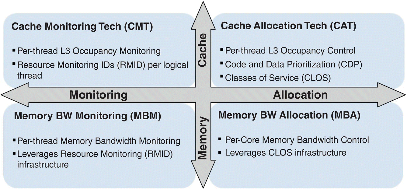
Figure 7.18 Intel Resource Director Technology.
The academic community [40] has shown the benefits that can be achieved by monitoring shared resources usage and then allocating these shared resources to specific VMs. In an environment with nine VNFs executing simultaneously on isolated CPU cores, without isolation of the LLC shared resource, the LLC contention causes up to ~50% throughput degradation for some of the VNFs, others were minimally impacted due to their workload limited usage of the LLC, and a latency degradation of up to ~30%. When the shared LLC resource was properly allocated and isolated for specific VNFs, the throughput degraded by up to ~2.5% and the latency by up to ~3%, a significant improvement showing the key benefit of these technologies.
In the upcoming 5G network edge environment where we can expect to have most functionality being implemented at VNFs running on high volume servers, use of this technology will be key to guarantee a level of QoS.
7.5 Part III: Software‐Defined Disaggregated RAN
7.5.1 RAN Disaggregation
Disaggregation of the RAN aims to deal with the challenges of high total cost of ownership, high energy consumption, better system performance by intelligent and dynamic radio resource management (RRM), as well as rapid, open innovation in different components while ensuring multi‐vendor operability.
3GPP has already defined a number of disaggregation options. These are summarized in Figure 7.19.
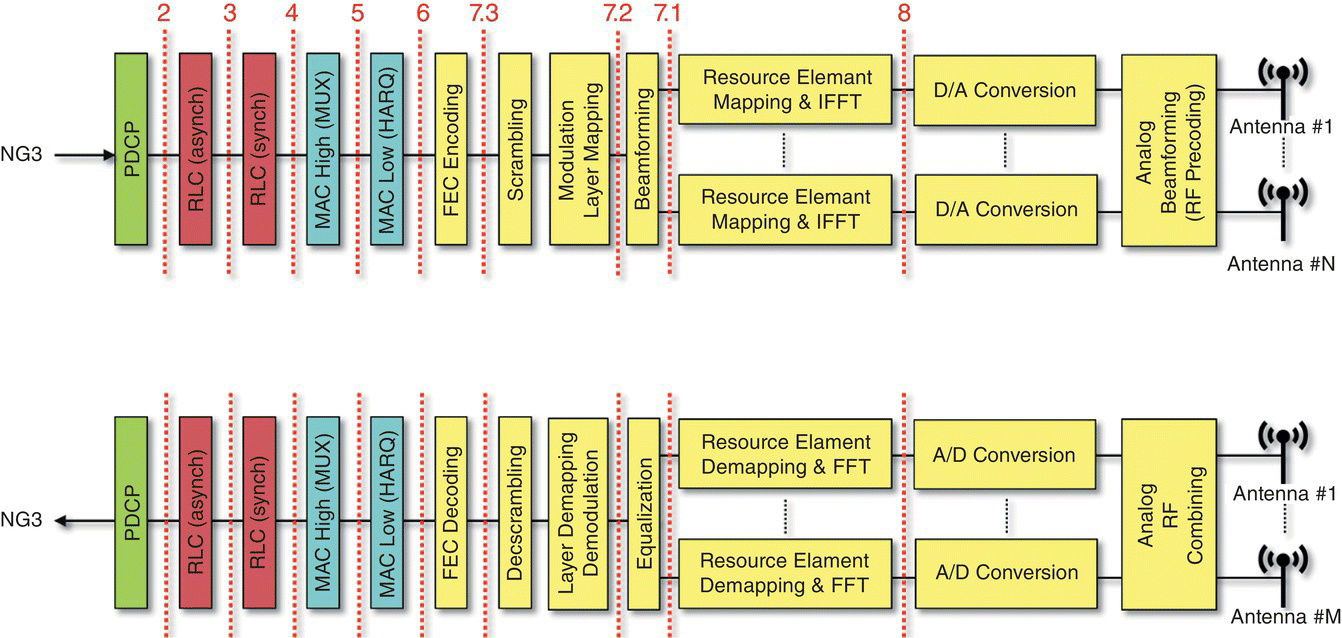
Figure 7.19 3GPP specified RAN disaggregation options.
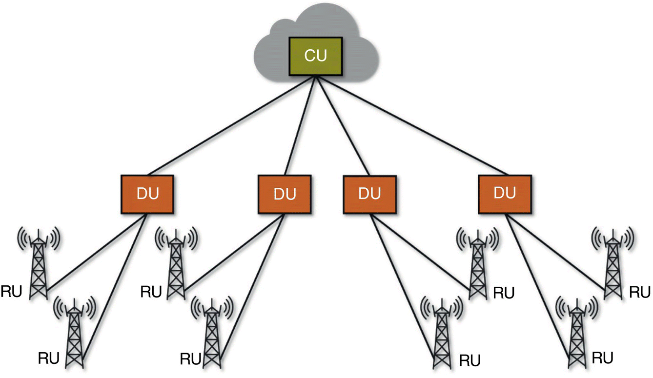
Figure 7.20 RAN disaggregation and distributed deployment.
The disaggregation solution needs to enable a distributed deployment of RAN functions over the coverage area, as illustrated in Figure 7.20, where:
- CU will centralize the “packet processing functions,” realize them as virtualized network functions running on commodity hardware, and place them in geographically centralized telco cloud locations.
- DU will realize “baseband processing functions” across cell sites, realize them as virtualized network functions running on commodity hardware, allowing for possible hardware acceleration using, e.g. FPGAs.
- RU will enable geographical coverage using “radio functions” across antenna sites, realized on specialized hardware.
The disaggregation solution needs to be flexible, in that, based on the use case, geography, and operator choice, it should enable the possibility of realizing the base stations as (i) three components (CU, DU, and RU), (ii) two components (CU and DU + RU, and/or CU + DU and RU), or (iii) all in‐one (CU + DU + RU).
The current industry trend has focused on an option 2‐split between CU and DU and an option 7/8‐split between DU and RU. This is illustrated in Figure 7.21.
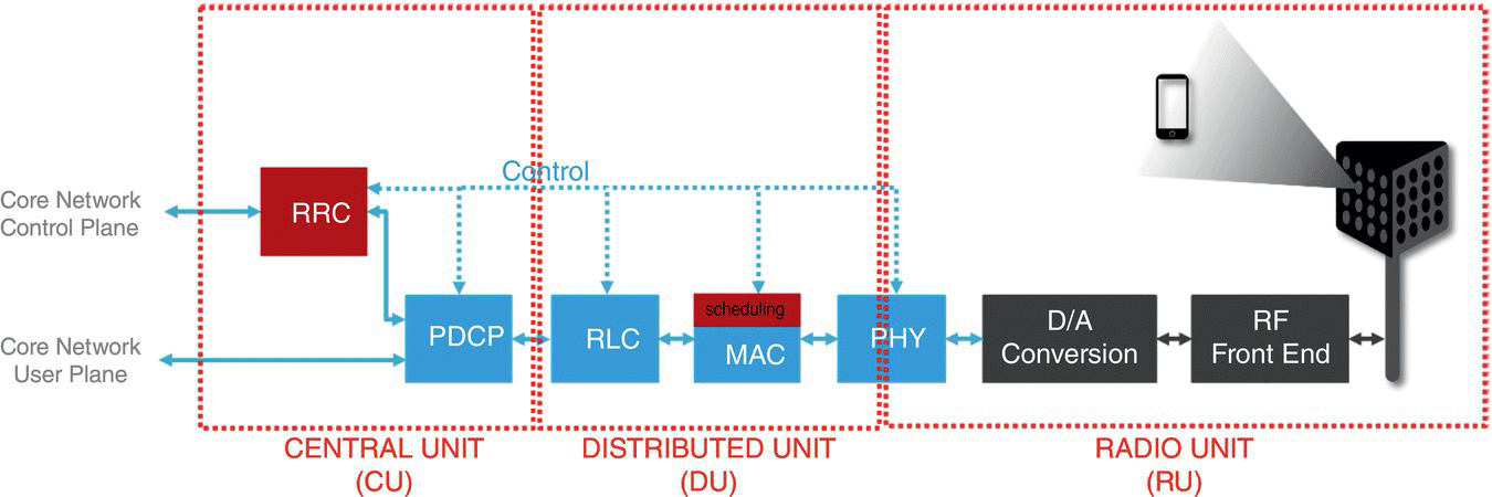
Figure 7.21 Current trend in CU–DU–RU disaggregation.
7.5.2 Software‐Defined RAN Control
In the cellular network, RAN provides wide‐area wireless connectivity to mobile devices. Then, the fundamental problem it solves is determining how best to use and manage the precious radio resources to achieve this connectivity. On the path toward 5G, with network densification, and the availability of different types of spectrum bands, it is increasingly a more difficult task to allocate radio resources, implement handovers, manage interference, balance load between cells, etc. The current RRM control that is distributed across the RAN nodes (base stations) is suboptimal in achieving the conduct of these functions in an optimal way. Thus, it is necessary to bring software‐defined controllability to RAN to increase system performance.
The fundamental goal is to allow for programmatic control of RRM functions. This can be achieved by decoupling the associated intelligence from the underlying hardware and stack software. Within the RAN, the RRM functions (Figure 7.21) reside in the CU (in the RRC), and in the RU (in the MAC). Then, the decoupling of the RRM functions from the underlying stack software effectively means:
- Further disaggregating the CU into user and control planes: CU‐U and CU‐C, where CU‐C contains all RRC‐side RRM functions.
- Clearly defining open interfaces between CU‐C and CU‐U, as well as between CU‐C and DU.
- Realizing the CU‐C as an SDN‐controller.
- Explicitly defining a “Radio Network Information Base (R‐NIB),” using:
- RAN nodes: CUs, DUs, RUs, mobile devices (UE, IoT, etc).
- RAN links: all links between nodes that support data and control traffic.
- Node and link attributes: static, slow‐varying and fast‐varying parameters that collectively define the nodes and the links.
- Maintenance and exposure of the R‐NIB using an open interface to RRC‐side RRM functions that are realized as SDN applications.
- Allowing for programmatic configuration of the MAC‐side RRM functions using open interfaces.
The software‐defined control of the RAN will allow for:
- Democratization of the innovation within the RAN: The control plane–user plane separation and open, clearly defined interfaces between the disaggregated RAN components as well as between the RAN control and associated control applications, allow for innovative, third‐party control solutions to be rapidly deployed regardless of which vendors have provided the underlying hardware and software solution.
- Holistic control of RRM: Software‐defined control of RAN will allow for logically centralized (within limited‐geography) control of RRM. Then, for a given active user, using innovative control applications, operators are empowered to conduct dynamic selection of any radio beam within reach across all network technologies, antenna points, and sites using a global view that minimizes interference, and thus maximizes observed user QoE. This can be achieved by applying carrier aggregation, dual connectivity, coordinated multi‐point transmission as well as selection of multiple‐input multiple‐output and beamforming schemes using a global view of the wireless network.
- Use‐case‐based management of the RAN: Software‐defined RAN control will allow for the integration of performance‐based decisions with policy‐based constraints, with such constraints to be dynamically set, based on use cases, geographies, or operator decisions.
The architecture that allows for software‐defined RAN control is illustrated in Figure 7.22. In the figure, we note that the RRC is disaggregated into two distinct functional components: Core Network Control Plane Forwarding, which is responsible from forwarding control plane traffic between the UEs and the mobile core network, and RAN Near Real‐Time Software‐Defined Control, which is responsible from conducting all RRC‐level RRM functions, as well as SON control applications in a programmable way. Following our SDN‐based terminology, we also describe the MAC‐level RRM function, namely the scheduler, as the RAN Real‐Time Control in the figure. While the Real‐Time Control is not disaggregated and logically centralized in this architecture, it is possible for this component to be programmatically configured by the Near Real‐Time Controller.

Figure 7.22 RAN near real‐time and real‐time software defined control.
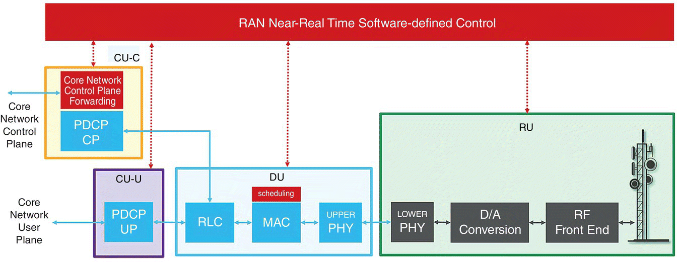
Figure 7.23 Disaggregated and software defined controllable RAN architecture.
Combining disaggregation and software‐defined control results in a RAN architecture is illustrated in Figure 7.23. As observed, the disaggregated, and software‐defined controllable RAN is composed of RAN Near Real‐Time Software‐Defined Controller, CU‐C, CU‐U, DU, and RU components. While RU and DU are distributed across the geography across antenna sites and cell sites, respectively, the near real‐time controller, CU‐C and CU‐U can be instantiated as virtualized network functions at edge clouds.
7.6 Part IV: White‐Box Solutions for Compute, Storage, Access, and Networking
The rise of white box for compute, storage, and networking is shaping how modern networks will take advantage of cloud technologies at the edge of the network to meet the demand of end devices for better experiences. High volume servers, switches built using merchant silicon, and appliances can now perform what used to be dedicated to special hardware and ASICs such as signal processing, packet processing, and adopt open source software available for the “white box.”
Today most RAN, switches and optical deployments are hardwired and static, inhibiting dynamic services on demand and flexibility, leading to time‐sensitive truck roles, higher costs, and loss of revenue opportunities for all. For example, white box deployed RAN for emerging 5G networks will enable real time control over microservices that were previously at the mercy of a specific implementation approach until a new “G” generation arrives:
- Open Disaggregated Interoperable RAN and CORE network layers that can be upgraded on a software development time scale versus a hardware development time scale.
- Standard‐based API from each component that can enable innovation.
- Disaggregated and software controlled radios that span into split architecture options between, e.g. 5G RUs, 5G DUs, 5G CUs.
- Run time SW plug‐ins to meet the end user’s device behaviors and policies.
In general, the “white box” term has been applied to no‐name computers. The same ODMs (original design manufacturers) that produced them are getting into the game of manufacturing white‐box platforms that meet certain standards such as OCP (Open Compute Platform; https://www.opencompute.org). White box platforms look just like any other purposeful hardware such as switch, chassis, or high volume servers. Furthermore, white boxes promise cost savings and greater flexibility over traditional purposeful hardware appliances.
Google G‐Scale Network [14] has shown some of the benefits of using white box platforms built using merchant switching silicon to enable new functionalities such as disaggregation of control from data planes, i.e. SDN, and taking advantage of new services. White box platforms, e.g. switches, come with their operating systems, usually Linux based and ideally hardware agnostic, and specific software stacks to manage and set up their control and data plane. For example, in the case of a switch or white box radio or IP equipment, the software needs to seamlessly integrate with existing L2/L3 topologies and support a basic set of features. Beyond the separation of control from data planes and availability of open source software, white box platforms are more valuable if they interact with SDN controllers. Some of these white box products, e.g. switches, come with software control which interfaces to multiple controllers. By controllers we mean software defined everything where white box platforms can be configured or imaged to be a network appliance, a switch, or even a RAN. Beyond this, there could be new capabilities delivered as a result of “opening up” the network functions, e.g. switch, appliances, etc. as well as being able to use many new open source tools that can be used, that is the best foundation for reaping the benefits of network functionality implemented on white box. The advantage of this approach is that network functions, e.g. switches or others, can be customized to meet an organization's specific business and networking needs. Due to their flexibility, white box platforms can support a range of open source tools to operate, control, and manage networks with more solutions from various consortiums coming to markets. To name a few, the ONF Central Office Re‐architected as Datacenter [4] defining multi‐access edge network running on high volume servers, the ONAP [5], a platform for real‐time, policy‐driven orchestration and automation of physical or VNFs providing a complete lifecycle management to on‐board and manage functionality, Akraino [41], an integration platform for the edge of the network, and the Open Platform for NFV [42], an integration platform facilitating the development and validation of VNFs.
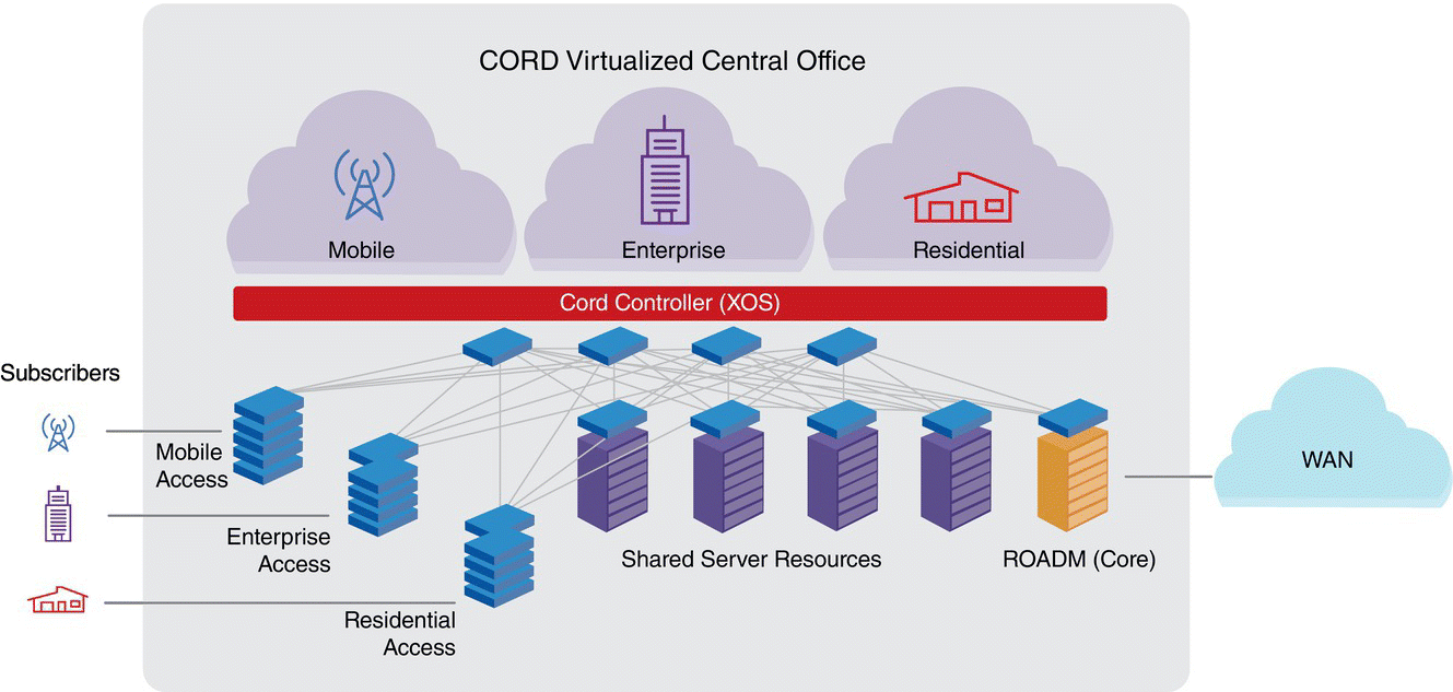
Figure 7.24 CORD high‐level architecture.
For example, ONF's open source CORD edge cloud hardware reference model [43, 44] illustrated in Figure 7.24 has commodity off‐the‐shelf servers (COTS) inter‐connected by white box software defined programmable switches and specialized or white box access hardware to connect the end‐users (residential, commercial, or mobile). ONF recommends OCP‐certified hardware but this is not an essential requirement.
CORD integrates the relevant open source components packaged as a standalone POD that is easy to configure, build, deploy, and operate. Various configurations of CORD are being deployed in production networks by major carriers around the world, making it an ideal experimental platform with a compelling tech transfer story. CORD's software reference model is shown in Figure 7.25.
CORD arranges the software defined programmable switches in a leaf‐spine fabric, enabling a highly scalable platform. It orchestrates the servers with Kubernetes. It is also possible to engage OpenStack, or the combination of the two for this purpose. The software defined control of both the switching fabric and the access devices are conducted by ONF's ONOS controller and associated ONOS applications. In Figure 7.25, two access technologies are illustrated: mobile and broadband. For mobile access, ONOS controls the disaggregated, or all in one base stations using the near real‐time RAN control application. For broadband access, white box realizations of optical line terminations (OLTs) are turned into SDN controllable forwarders via ONF's virtual OLT hardware abstraction (VOLTHA) platform. Subsequently, a virtual OLT (vOLT) application running on ONOS performs the associated control. XOS is CORD's services controller and it integrates the disaggregated components into a self‐contained system. It defines a set of abstractions that govern how all the individual components interconnect to form a service mesh, how individual subscribers acquire isolated service chains across the service mesh, and how operators monitor, provision, and configure CORD. For monitoring, XOS engages open source platforms such as Prometheus, Grafana, Kibana, etc. Users wanting to differentiate their offering could replace specific module or work with the open source community to improve functionality or performance of specific components or the system as a whole.
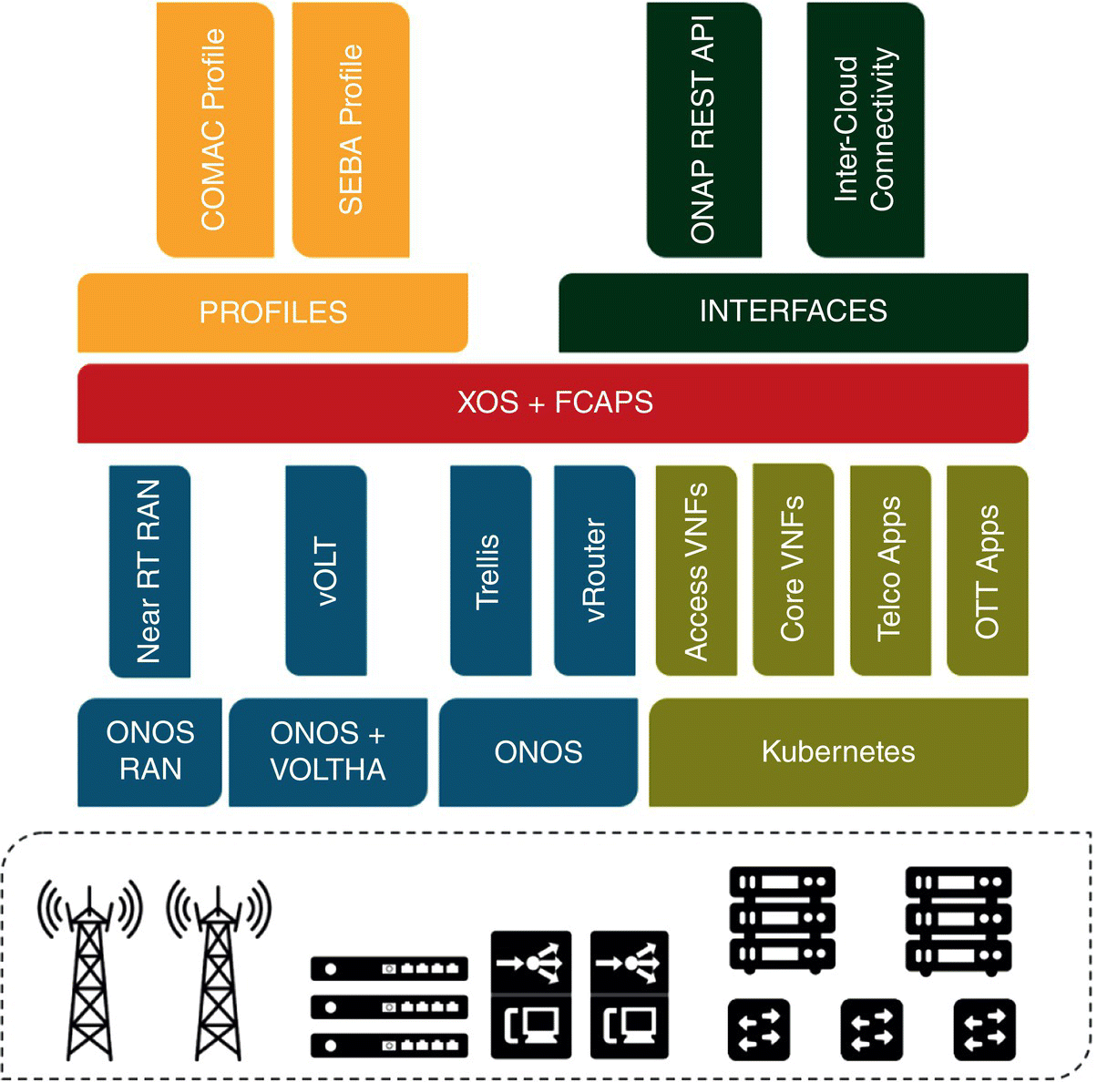
Figure 7.25 CORD software reference model.
7.7 Part V: Edge Cloud Deployment Options
There is no single physical location that can be defined as the network edge. In fact, as illustrated in Figure 7.26, multiple edge locations in the network exist:
- Device edge: Many of the end user devices are furnished with significant compute, storage and network resources. This effectively enables the zero‐hop device edge, where potentially some workloads may run, especially those with the most stringent latency requirements. The device edge needs a remote control and management platform. This will be located at either another edge cloud location, or at the central (telco or public) cloud.
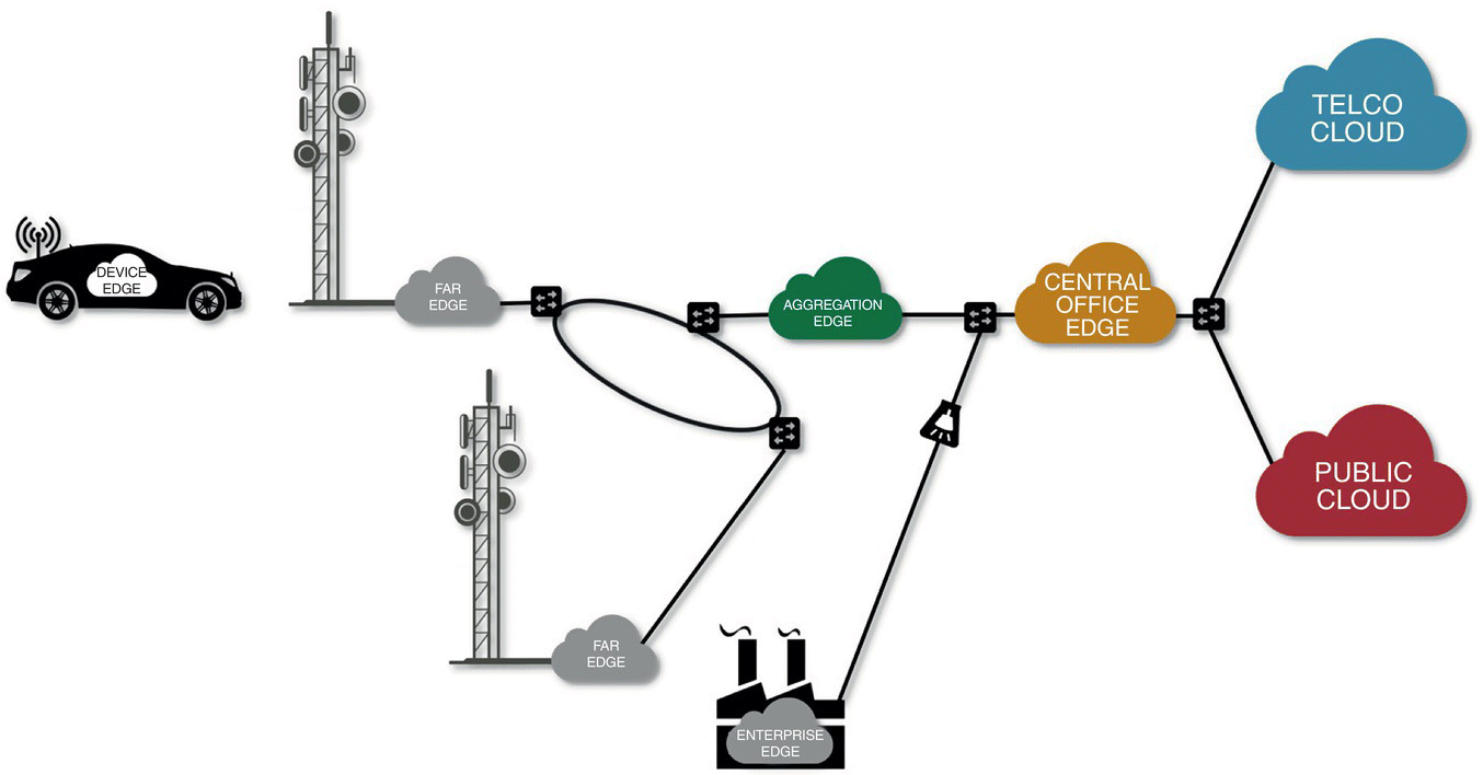
Figure 7.26 Edge cloud locations.
- Far edge: An edge cloud may exist at every base station site, resulting in a cell‐specific edge cloud platform. The far edge has physical limitations in real estate and power, making it resource constrained. At the same time, the far edge is the closest network‐side edge location, potentially providing lowest latencies and higher throughputs than other network‐side edges. The constrained resources coupled with the potential for high performance mean that intelligent workload placement orchestration overseeing efficient utilization of far edge resources is critically important.
- Aggregation edge: An edge cloud may also exist at the base station aggregation sites. Relative to the far edge, the aggregation edge may have more resources for pooling, allowing workloads serving geographies covered by multiple base stations to be hosted here.
- Central office edge: A central office (CO), owned by an operator, is usually located in the center of a town, host switching and routing systems that allow for local traffic switching as well as routing to other central offices, or external networks for wireline, fiber and mobile access [45]. Up until recently, systems in the COs have been very hardware centric. Today, increasingly, we observe such systems being replaced by VNF workloads that resemble those found in cloud or datacenters. Therefore, a CO is the first natural operator‐owned edge cloud location.
In addition to these locations, an additional location exists:
- Enterprise edge: In parallel with operators' efforts on defining and deploying edge clouds, cloud providers are also making a play. For them, the natural edge cloud location is the enterprise datacenter. The focus here is to provide machine learning and inference‐based intelligence to enterprises' IoT solutions by bringing models that used to run in the cloud down to the edge. Unlike operators' approaches, the last mile connectivity between the enterprise edge and the end user and IoT devices is abstracted out from the cloud providers' edge, provided that this connectivity does not bring substantial performance degradation. Similarly, the enterprise edge is agnostic to the backhaul technology that enables its connectivity to the public cloud. This connection can be fiber, wireline, or mobile. One needs to ensure that this connection satisfies the requirements of the specific machine learning and inference intelligence that will be distributed between the edge and the cloud.
Figure 7.26 provides an overview of all of the above described edge locations.
In the distributed network cloud paradigm, operators' disaggregated VNF workloads will be distributed across the central telco cloud and edge cloud locations so that performance requirements for different business verticals and use cases are met while any potential efficiency is leveraged via resource pooling. These workloads include the virtualized components of the RAN (DU, CU‐U, and CU‐C), software‐defined controller for the RAN (SD‐RAN), core network user plane function (UPF), core network control plane functions (CPFs) as well as operator provided applications such as voice, video streaming, and AR/VR. Similarly, workloads for machine learning and inference‐based intelligent IoT operations (Inference, ML) as well as any enterprise and/or OTT applications and services (App) will be distributed across the public cloud, optionally the telco cloud, as well as the edge cloud locations. A sample workload distribution across the distributed network cloud is illustrated in Figure 7.27.
A more involved synergy between the telco network cloud and the public cloud is also possible. The disaggregation of the access and connectivity VNFs allows a deployment of components where data plane components are hosted at operators' central and edge cloud locations, and the control plane components are hosted at a public Cloud Service Provider's cloud, as shown in Figure 7.28.
A deployment example has been demonstrated by ONF at the Mobile World Congress in 2019. In this demonstration, an edge cloud located at ONF's booth in Barcelona was connected to two central Telco Cloud locations, one inside Deutsche Telekom's datacenter in Warsaw, and another inside Turk Telekom subsidiary Argela's datacenter in Istanbul. The edge cloud platform ran CORD to control and manage COTS, white box switches as well as programmable access equipment. The edge cloud in question provided a shared platform for two specific access technologies, broadband and cellular. As such, the OLT was realized as a white box solution with a VOLTHA enabling Openflow‐based programmability to broadband access using a vOLT application running on ONOS. The broadband service subscriber control was conducted by a simplified virtual broadband network gateway that was realized as a VNF hosted at the edge cloud.

Figure 7.27 Sample distribution of VNF and application workloads across a distributed network cloud.

Figure 7.28 Telco cloud–public cloud inter‐operation.
For cellular access, a disaggregated, commercially available small cell that allowed for programmatic control was utilized. The CU was realized in a microservices architecture using three distinct containerized, inter‐connected components. The SD‐RAN control allowed for programmatic network slicing using an ONOS application called ProgRAN. Further details on software defined network slicing is given in the Section 7.8.
The cellular network core network was distributed across the edge and central telco clouds in the demonstration, with containerized workloads for UPFs hosted at the edge, and all containerized CPFs hosted at the central telco cloud in Warsaw. The global end‐to‐end network orchestration was conducted by the open source ONAP which was hosted at the second central telco cloud in Istanbul.
A CDN‐based streaming video service was included in the demonstration as a representative OTT application that could share a multi‐tenant edge cloud. This service was developed using open source components, with NGINX server with local content cache hosted at the edge cloud providing streaming service to mobile handsets with very low pre‐roll latency and uninterrupted streaming experience. A remote content store was developed using VLC and remote streaming of this content to NGINX server was enabled by Wowza. Both VLC and Wowza were hosted at the central Telco cloud in Warsaw.
An optical network unit, representing a broadband subscriber location, was connected to the OLT hosted inside the edge cloud. Similarly, a couple of mobile handsets were connected to the base station with the virtualized components hosted at the edge cloud.
Two network slices were designed on ONAP, and the corresponding profiles were pushed down to the edge cloud for execution. CORD's XOS, upon receipt of these profiles, coordinated the creation and execution of these slices using the ProgRAN application running on ONOS. One slice was for users streaming video content and another was for users downloading a file with best effort Service Level Agreement.
A high‐level diagram of the ONF demonstration is given in Figure 7.29. As shown in the diagram, the demonstration enabled isolation between the user plane and control/management plane traffic by using two distinct network interfaces on Kubernetes. While the user plane enjoyed acceleration via an SR‐IOV interface, the control/management plane utilized Calico. It should be noted here that due to the nature of the cellular network realization, this meant that the core network user plane container required dual connectivity, one for the Calico network, and another for the SR‐IOV network. This was enabled by making use of Multus.
7.8 Part VI: Edge Cloud and Network Slicing
Network slicing is a mechanism to create, and dynamically manage functionally discrete virtualized networks over a common 5G infrastructure, one for each use case/tenant. It realizes the expected benefits of virtualization by providing a model for operationalizing virtualized, and programmable cloud‐based infrastructure. Then, leveraging disaggregation, NFV and SDN, network slicing is a mobile networking platform using scalable and elastic access, network and network resources provided “as‐a‐service” to use cases and tenants in a given geography using 3GPP‐standardized technologies. As illustrated in Figure 7.30, the network resources comprise storage, compute, and networking resources distributed across central and edge cloud locations, and service resources include virtualized network functions that are instantiated at various locations in the distributed 5G network. If network slicing was to include slicing of the RAN as well, then we would need to add the service resources of disaggregated RAN virtualized network functions as well as access resources of the time‐frequency resource blocks to the list of resources that are to be provided to use cases and tenants in a scalable and elastic manner.
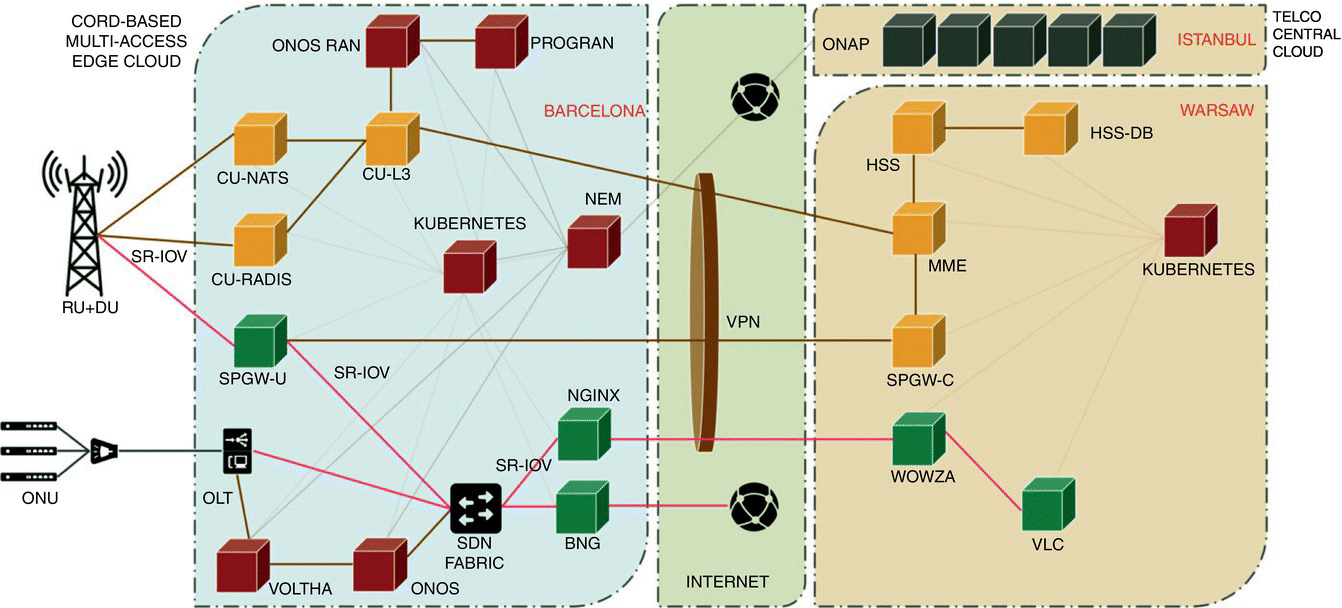
Figure 7.29 ONF's distributed network cloud architecture demonstrated at Mobile World Congress 2019.
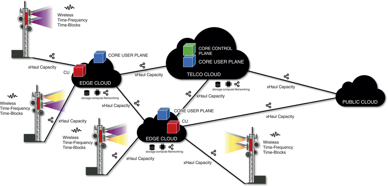
Figure 7.30 5G network resources and capabilities offered as‐a‐service to use cases and tenants with network slicing.
For a given use case or tenant, a network slice is designed by specifying slice attributes that include latency, throughput, reliability, mobility, geography, security, analytics, and cost profile parameters. These attributes are then translated into composable access, network, and service resources that are selected in optimally selected geographical locations, including the edge cloud. A key component of network slicing is automated composition of slice specific service chains and their life‐cycle management. The designed and composed service chains with associated elastically and scalable allocated resources for the slices are then delivered for the specific use cases or tenants.
An example is illustrated in Figure 7.31, where two network slices are constructed for distinct use cases. The first slice has distinct RAN CP (CP1) chained to a core user plane (UPF1) service, both realized at the edge, enabling a local break‐out. A component of a tenant specific application is also instantiated at the edge and is attached to the egress of this service chain. The user plane part of the chain is completed by connecting the remainder of the tenant specific application that resides in the public cloud. The second slice also has a slice specific CP (CP2) and core network user plane (UPF2) chained together. However, this time, the UPF workload is instantiated at the telco cloud. A tenant specific application is also instantiated at the telco cloud for the second slice. In the example, both slices share the near real time SD‐RAN controller VNF and as well as the core network CPF VNFs. The time‐frequency mobile resource blocks are divided in an elastic and scalable way among the two network slices.

Figure 7.31 Two sample network slices and associated service chains.
Network slicing enables the last component of the network transformation, namely, cloudification. It enables multiple use cases and tenants to share the access, network, and service resources of a common, distributed infrastructure, thereby catalyzing new revenue opportunities for the operators.
Due to its inherent nature, the edge cloud is resource limited. In a given geography, so is the RAN. Therefore, workload placement and automation of resources allocation are crucial components of network slicing.
7.9 Summary
With 5G, a transformation of the network architecture is underway, paving the way to a distributed network cloud. In this new paradigm, edge cloud plays an essential role, as a location providing traditional cloud resources of compute, storage, and networking, as well as network cloud specific resources, such as spectrum in close proximity to the end users. This in turn, allows operators to provide optimized access and connectivity options to different use cases and business verticals.
The edge cloud is where access meets the cloud. As such, it would be unwise to develop an edge cloud architecture that concentrates on a solution just for access or just for cloud. In this capacity, the overall architecture should allow for:
- Hosting of operators' VNFs by providing all necessary scaling, elasticity, and networking requirements.
- Programmatic creation and maintenance of service chains that may transcend a single edge cloud, and potentially include multiple edges, and central clouds, based on recipes provided by global orchestration.
- Hosting of latency, bandwidth, and traffic localization sensitive end user and OTT applications, functions and microservices.
- Federated network slicing that includes service chains of operator VNFs and end‐user/OTT applications.
Acknowledgments
The authors would like to thank Tom Tofigh of QCT and Sameh Gobriel of Intel for their help in writing this chapter.
References
- 1 Wikipedia (2019). Software‐defined networking. https://en.wikipedia.org/wiki/Software‐defined_networking (accessed 9 October 2019).
- 2 ETSI (2013). Network Function Virtualization (NFV). http://portal.etsi.org/portal/server.pt/community/NFV/367 (accessed 9 October 2019).
- 3 ONF (2018). Open Networking Foundation. https://www.opennetworking.org (accessed 9 October 2019).
- 4 ONF (2018). CORD. https://www.opennetworking.org/cord (accessed 9 October 2019).
- 5 ONAP (2018). Open Network Automation Platform. https://www.onap.org (accessed 9 October 2019).
- 6 Telecom Infra Project (n.d.). OpenRAN. https://telecominfraproject.com/openran (accessed 9 October 2019).
- 7 O‐RAN (2018). O‐RAN Alliance. https://www.o‐ran.org (accessed 9 October 2019).
- 8 Telecom Infra Project (n.d.). OpenRAN 5G NR. https://5gnr.telecominfraproject.com (accessed 9 October 2019).
- 9 Telecom Infra Project (2019). Open RAN 5G NR Base Station. https://5gnr.telecominfraproject.com/wp‐content/uploads/sites/27/PG‐Charter‐5G‐NR‐Base‐station.pdf (accessed 9 October 2019).
- 10 Vogels, W. (2017). Unlocking the Value of Device Data with AWS Greengrass. https://www.allthingsdistributed.com/2017/06/unlocking‐value‐device‐data‐aws‐greengrass.html (accessed 9 October 2019).
- 11 O‐RAN Alliance (2018). O‐RAN: Towards an Open and Smart RAN. https://static1.squarespace.com/static/5ad774cce74940d7115044b0/t/5bc79b371905f4197055e8c6/1539808057078/O‐RAN+WP+FInal+181017.pdf (accessed 9 October 2019).
- 12 OpenFlow (2011). OpenFlow. https://openflow.stanford.edu (accessed 10 October 2019).
- 13 P4 (2015). P4 Language Consortium. https://p4.org (accessed 10 October 2019).
- 14 Koley, B. (2014). Software Defined Networking at Scale. https://static.googleusercontent.com/media/research.google.com/en//pubs/archive/42948.pdf (accessed 10 October 2019).
- 15 P4 Language Consortium (2017). P416 Language Specification. https://p4lang.github.io/p4‐spec/docs/P4‐16‐v1.0.0‐spec.html (accessed 10 October 2019).
- 16 P4 Language Consortium (2017). P4Runtime. https://p4.org/p4‐runtime (accessed 10 october 2019).
- 17 Schmitt, P., Landais, B., and Young, F. (2017). Control and User Plane Separation of EPC nodes (CUPS). http://www.3gpp.org/cups (accessed 10 October 2019).
- 18 Rajan, A.S., Gobriel, S., Maciocco, C. et al. (2015). Understanding the bottlenecks in virtualizing cellular core network functions. https://ieeexplore.ieee.org/document/7114735 (accessed 10 October 2019).
- 19 Sunay, O., Maciocco, C., Paul, M. et al. (2019). OMEC. https://www.opennetworking.org/omec (accessed 10 October 2019).
- 20 OpenAirInterface (OAI) (2019). OpenAirInterface. https://www.openairinterface.org (accessed 10 October 2019).
- 21 Facebook Connectivity (2018). Magma. https://connectivity.fb.com/magma (accessed 10 October 2019).
- 22 Cloud Native Computing Foundation (2018). kubernetes. https://kubernetes.io (accessed 10 October 2019).
- 23 Intel/multus‐cni (2018). Multus‐CNI. https://github.com/Intel‐Corp/multus‐cni (accessed 10 October 2019).
- 24 HashiCorp (2017). Consul. www.consul.io (accessed 10 October 2019).
- 25 Saur, K. and Edupuganti, S. (2018). Migrating the Next Generation Mobile Core towards 5G with Kubernetes. Container Days, Hamburg.
- 26 Intel Corporation (2017). Enhanced Platform Awareness in Kubernetes. https://builders.intel.com/docs/networkbuilders/enhanced‐platform‐awareness‐feature‐brief.pdf. Code at: https://github.com/Intel‐Corp/sriov‐cni (accessed 10 October 2019).
- 27 DPDK (2014). Data Plane Development Kit. https://www.dpdk.org (accessed 10 October 2019).
- 28 Intel (2018). DPDK Intel NIC Performance Report Release 18.08. http://fast.dpdk.org/doc/perf/DPDK_18_08_Intel_NIC_performance:report.pdf (accessed 10 October 2019).
- 29 Microsoft (2017). Introduction to Receive Side Scaling. https://docs.microsoft.com/en‐us/windows‐hardware/drivers/network/introduction‐to‐receive‐side‐scaling (accessed 10 October 2019).
- 30 ETSI (2017). ETSI TS 129 281. https://www.etsi.org/deliver/etsi_ts/129200_129299/129281/08.00.00_60/ts_129281v080000p.pdf (accessed 10 October 2019).
- 31 Intel (2018). Dynamic Device Personalization for Intel Ethernet 700 Series. https://software.intel.com/en‐us/articles/dynamic‐device‐personalization‐for‐intel‐ethernet‐700‐series (accessed 10 October 2019).
- 32 PCI SIG (1994). Specifications. https://pcisig.com/specifications/iov (accessed 10 October 2019)
- 33 Zhou, D., Fan, B., Lim, H. et al. (2013). Scalable, high performance Ethernet forwarding with CuckooSwitch. ACM Conference on Emerging Networking Experiments and technologies (CoNEXT), Santa Barbara, CA.
- 34 Scouarnec, N. (2018). Cuckoo++ hash tables: high‐performance hash tables for networking apps. ACM/IEEE Symposium on Architectures for Networking and Communications Systems.
- 35 Breslow, A.D. (2016). Horton tables: fast hash tables for in‐memory data‐intensive computing. USENIX Annual Technical Conference, Denver, CO.
- 36 Dietzfelbinger, M. (2005). Balanced allocation and dictionaries with tightly packed constant size bins. ICALP 2005.
- 37 Wang, Y. (2017).Optimizing Open vSwitch to support millions of flows. GLOBECOM 2017.
- 38 Wang, Y. (2018). Hash table design and optimization for software virtual switches. KBNets 2018.
- 39 Intel (n.d.). Intel Resource Director Technology. http://www.intel.com/content/www/us/en/architecture‐and‐technology/resource‐director‐technology.html (accessed 10 October 2019).
- 40 Tootoonchian, A., Panda, V., Lan, C. et al. (2018). ResQ: Enabling SLOs in Network Function Virtualization. https://www.usenix.org/system/files/conference/nsdi18/nsdi18‐tootoonchian.pdf (accessed 10 October 2019).
- 41 Linux Foundation Edge (2018). Akraino. https://www.akraino.org (accessed 10 October 2019).
- 42 Linux Foundation (2016). OPNFV. https://www.opnfv.org (accessed 10 October 2019).
- 43 Peterson, L., Al‐Shabibi, A., Anshutz, T. et al. (2016). Central office re‐architected as a datacenter. IEEE Communications Magazine 54 (10): 96–101.
- 44 Peterson, L., Anderson, T., Katti, S. et al. (2019). Democratizing the network edge. ACM SIGCOMM Computer Communication Review 49 (2): 31–36.
- 45 TIA (2018). Central Office Evaluation Strategy for Deployment of Information and Communications Technology (ICT) Equipment. Position paper.
