Chapter 2. MIMO and the 802.11n PHY
Row, row, row your boat,
Gently down the stream…
Increasing the speed of a network can be done in two ways. First, protocol designers can try to increase the raw speed as measured by the transmission rate, which might be termed the “go faster” approach. Increasing transmission rates has been the primary tool for the dramatic increase in wireless LAN speeds from 1 Mbps in the original 802.11 standard to 54 Mbps in 802.11a and 802.11g. Second, protocol designers can increase the speed perceived by users by increasing the efficiency of the protocol, to transmit more bits within a given period of time, an approach which might be called the “efficiency” approach. Although 802.11n uses both techniques, most of the gains come from dramatic increases in data rate. At the core of the “go faster” approach, 802.11n uses MIMO. Early 802.11n products transmitted at a data rate of 150 Mbps, and the standard laid out a clear path to data rates of up to 600 Mbps. These speeds are achievable only through the application of MIMO.
The Big Idea: MIMO and Data Streams
Before MIMO, 802.11 used a single data stream. A transmitter used one antenna, and a receiver used one antenna.[6] The transmission link in pre-802.11n devices can be described in terms of its two components. It was called Single-Input because the receiver used one antenna, and Single-Output because the transmitter used only one antenna. Taken together, the communication system was called Single-Input/Single-Output (SISO).
Between the two endpoints in a SISO system flows one set of data, called a stream. If a data link is like a highway, then SISO is a two-lane country highway. (I’m stretching the analogy slightly because highways are bidirectional but 802.11 is half-duplex, so bear with me.) The highway certainly works—traffic can move from one point to the next. 802.11 was a successful technology when 802.11a/g systems were commonplace. However, there was a speed limit. The two-lane country highway had become too popular, and the 802.11 working group needed a solution. One method would be to increase the speed limit along our road. Instead of having cars travel at highway speeds of 60 miles (100 kilometers) per hour, we can impose a new rule that cars on our two-lane highway need to go faster. Instead of what we think of as normal highway speeds, cars now need to travel at 250 miles (400 kilometers) per hour. Extending the highway analogy, the dramatic improvements required for driver alertness and reaction time at higher speeds are like Shannon’s Law.[7] Yes, it’s possible to increase the speed to increase throughput, but it requires that the endpoints in a communication system distinguish between finer and finer details.
Instead, to increase the throughput of our highway, we decide to widen it. Instead of a single lane in each direction, we have two lanes. Although there are certainly costs involved in widening the highway in terms of land use, perhaps a center divider, and traffic signals, we can keep the speed limit where we know most motorists can handle the driving task. Widening the highway is similar to what the 802.11 working group did with 802.11n. Instead of just a single transmitter and a single receiver in the system, both sides now have multiple antennas. That is, the receiver has multiple inputs, and the transmitter uses multiple outputs.[8]
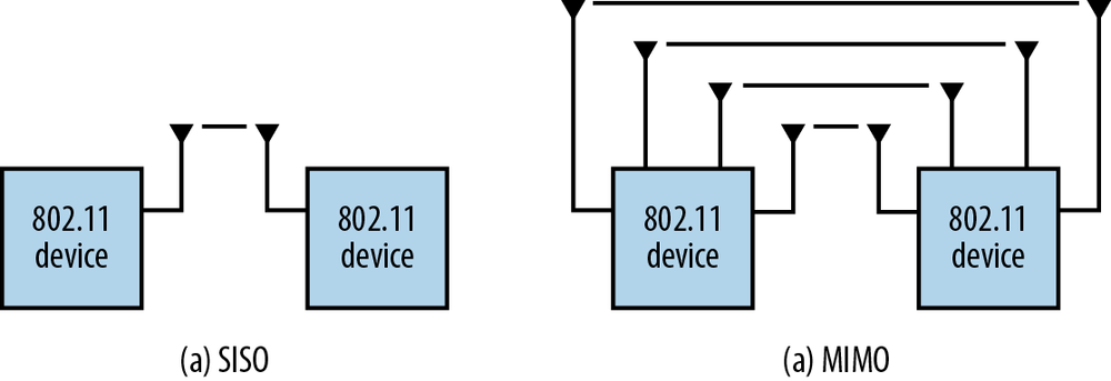
Figure 2-1 is a simplified high-level comparison of early 802.11 SISO systems to MIMO systems. In the SISO system, a single active antenna transmits to a single active antenna. Although SISO systems may have multiple antennas, only one is active for any given data frame. In the MIMO system, all of the antennas are active simultaneously. Each antenna in the MIMO transmitter sends its own data stream as input into the radio channel (hence, multiple input), and each antenna in the MIMO receiver collects its own data stream as output from the radio channel (hence, multiple output). The figure simplifies the picture by showing the simple case of a data stream going between pairs of antennas; in real-world systems, complex matrix math is used to create multiple data streams through the radio channel. In the ideal case, each pair of antennas in the MIMO system is capable of transmitting its own independent data stream, just as each lane on our highway carries its own set of cars.
Spatial Streams
Figure 2-1 in the previous section demonstrated the core idea of MIMO, which is the transmission of multiple data streams across the same radio channel. Each data stream is sometimes called a spatial stream because it is a separate path through the space between communication peers. When a MIMO link can only transmit using a single stream, it isn’t really MIMO and there isn’t any throughput improvement. (Imagine, I guess, our newly expanded four-lane country road being under construction and being back to a single lane in each direction.)
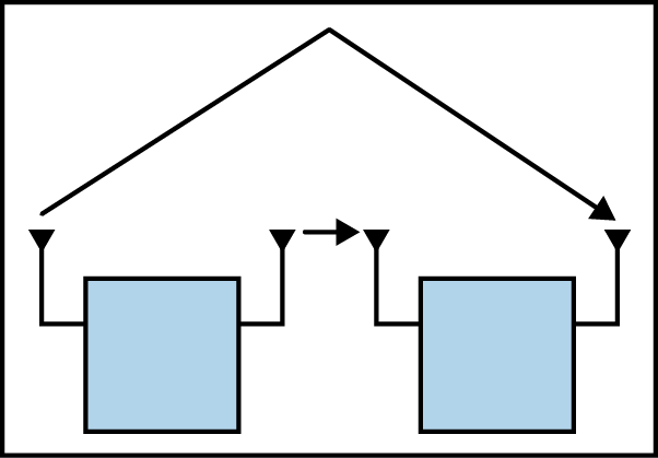
Spatial streams are created by having multiple independent paths through space between two devices; in a typical 802.11 network, those two devices are an access point and a client device. Figure 2-2 depicts a situation that was the bane of every 802.11a/b/g network administrator. In the figure, the transmitter and receiver have two paths. One is a direct line-of-sight path, and a second bounces off a wall and is exactly out of phase. If the two paths are being used to transmit the same set of bits, they will interfere destructively and there will be no signal to read at the receiver. However, MIMO systems perform a radio-channel alchemy of sorts. Instead of the worthless lead of a cold spot, MIMO exploits multiple paths through space and transmutes the lead into the gold of a hot spot with twice as much throughput. Because the two paths do not interfere with each other, independent transmissions can be sent through each path, doubling throughput. In the language of the field, the degree of similarity between the paths is called their correlation; in the figure, the two paths are said to be uncorrelated. When designing products, the RF designers typically spend quite some time thinking about antenna placement in order to minimize the correlation so that overall system throughput can be improved.[10]
802.11n reuses the channel structure and modulation techniques of 802.11a/g, called Coded OFDM. Each path in an 802.11n MIMO system is roughly equivalent to a single 802.11a/g transmission, but MIMO lets you double, triple, or quadruple up. 802.11n supports the use of up to four spatial streams. Another way to look at how spatial streams benefit 802.11 users is to look at a measurement called the spectral efficiency. It’s very easy to increase the speed of a network technology by increasing resource utilization. In 802.11, the key resource that needs to be optimized is the radio spectrum. Table 2-1 compares the 802.11 physical layers in terms of spectral efficiency, which is defined as the number of bits that can be sent per unit of spectrum; obviously, higher spectral efficiency is better. Because 802.11n has two channel widths, there is an entry for each channel width representing first-generation 802.11n hardware.
Radio Chains
Between the operating system and antenna, an 802.11 radio interface has to perform several tasks. When transmitting a frame, the main tasks are the inverse Fourier transform to turn the frequency-domain encoded signal into a time-domain signal, and amplification right before the signal hits the antenna so it has reasonable range. On the receive side, the process must be reversed. Immediately after entering the antenna, an amplifier boosts the faint signal received into something substantial enough to work with, and performs a Fourier transform to extract the subcarriers. In an 802.11 interface, these components are linked together and called a radio chain. Selecting the components to make up the radio chain is an important task for system designers, especially for those who make infrastructure devices. Generally, an access point will have much higher-quality components in its radio front-end, so an AP’s transmitted signal can go much farther than a client’s signal. To ensure that transmission and reception performance is closely matched, a condition referred to as a symmetric link, system designers must match the transmit and receive amplifiers; if especially powerful transmit amplifiers and high-gain antennas are used, designers must also ensure that the receive side has equal capabilities.
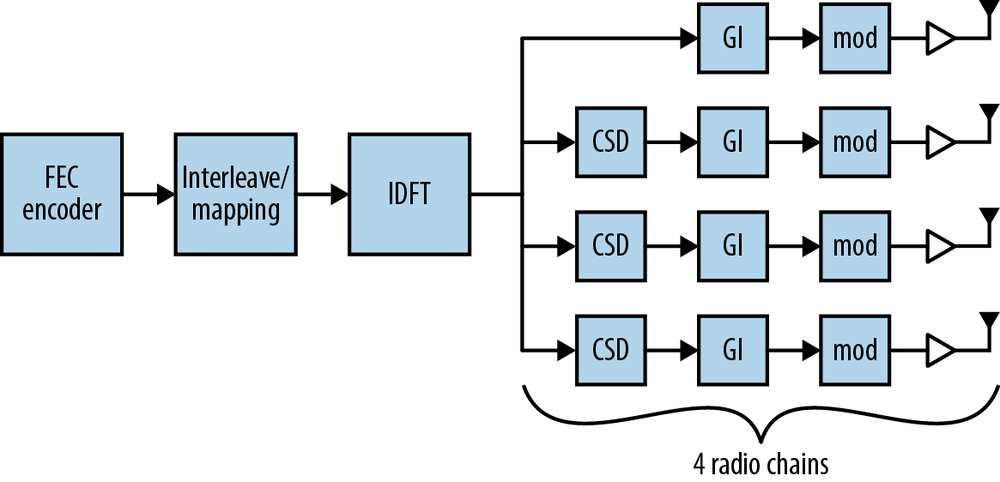
In the single-stream SISO world of 802.11a/g, only one Fourier transform and one amplifier are needed in the transmit chain. In order to transmit independent bits along each path, however, 802.11n requires multiple radio chains. If each spatial stream is to carry different bits, those bits must be processed by their own individual components. Figure 2-3 shows a simplified block diagram for an 802.11n interface with four radio chains. Building a radio interface that has multiple radio chains is a significantly more complex undertaking than making it work with just one radio chain. (For example, compare it to Figure 13-17 in 802.11 Wireless Networks: The Definitive Guide, which shows an OFDM PHY block diagram.) One of the major reasons that 802.11n has rolled out in phases is that it was necessary to tackle the relatively easy problem of building two-chain devices before building more complex three- and four-chain devices.[11]
Multiple radio chains can dramatically increase speed, but they have a negative effect as well. Fourier transforms use complex mathematics, and have significant power requirements. Amplifiers, too, are power-hungry. When receivers sample the channel, the power required depends on both the channel width and the number of spatial streams, both of which increase in 802.11n. Multiple radio chains can be used to increase speed, but they also consume significant power. Managing power consumption was an important task for the 802.11 working group, and it is an important task for 802.11n system designers building hardware based on power-hungry components.
Relationship Between Spatial Streams and Radio Chains
Each spatial stream needs to have an independent transmitter and receiver, so as you might have guessed, the number of radio chains must be greater than or equal to the number of spatial streams. As part of the MIMO extensions, 802.11n devices can negotiate the number of streams used, and devices will find the highest common speed they can use. In fact, there is a feature in 802.11n, Space-Time Block Coding (STBC), that requires two radio chains to transmit a single spatial stream. By spreading the spatial stream across two radio chains and two paths, it’s possible to increase the redundancy in transmission to offset path loss, though at the cost of overall transmission speed.
Even without STBC, “extra” radio chains offer a benefit. Many devices implement Maximal Ratio Combining (MRC), which uses information from all radio chains to process a frame. MRC works by cleverly combining the information received at each antenna by taking the strongest components of the received signal from each antenna. As a rough example, say that the transmitted signal consists of the sentence “Wireless networks are cool.” At the receiver side, it may be that one antenna receives “Wireless,” a second antenna receives “networks,” and the third antenna receives “are cool.” MRC enables the receiver to put all three pieces together into a coherent whole. At a more technical level, what MRC enables a receiver to do is pick the best antenna for each carrier in the 802.11n channel to compensate for individual fades in sub-channels.
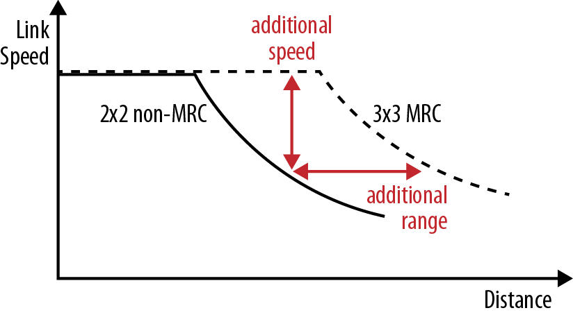
Additional information from the supplemental radio chains increases the accuracy of the MRC process. MRC is widely implemented in enterprise-grade APs, and it offers a benefit for all devices, including reception of transmissions from older non-802.11n devices. The antennas in many battery-powered devices are designed around the device case and aesthetics, not the optimal layout for maximum radio performance. By using a 3×3 AP, network administrators can gain extra sensitivity to decode the weak signals from even single-stream clients. Figure 2-4 shows the conceptual range increase when MRC is used. The solid line on the graph is the rate-over-range plot for reception of a two-stream device by a 2×2 MIMO system; the dashed line is the rate-over-range plot for reception of the same two-stream transmission by a 3×3 MIMO system. There is no increase in peak speed because both systems are operating as two-stream receivers. However, the additional range from MRC means that for a given distance, MRC yields higher data rates. Conversely, for a given data rate, the MRC-enabled receiver can hear weaker signals and enable greater range.
[6] Most 802.11 devices used antenna diversity, which is a way for a device to pick the “best” antenna out of a set. For any given transmission, only one antenna was active.
[7] Shannon’s Law is a mathematical relationship between the bit rate of a channel, as described by the bandwidth of the channel and its signal-to-noise ratio. Effectively, it states that the speed of a transmission channel can be made as large as desired as long as the signal-to-noise ratio increases in tandem.
[8] One reviewer asked how to work wider channels into my analogy, and the best I could come up with is that wider channels are like wider lanes. If we widen our two-lane highway so the lanes are wider, articulated tractor-trailer trucks are able to use the road and increase the “throughput” of the highway as measured in cargo, instead of the number of motorists per unit of time.
[9] It’s even possible to combine both diversity and MIMO in the same system, but the benefits are beyond the scope of this book, and certainly beyond the scope of a sidebar.
[10] Multipath is a key ingredient to the success of a MIMO system. As one reviewer put it, “In space, nobody can hear you scream, and MIMO doesn’t work because there are no uncorrelated paths.” That is, if there is only one path between two points, what are you going to bounce off of?
[11] We’ll return to the full block diagram; I’ve made some simplifications in this picture to show how data flows. The purpose of this figure is to illustrate the difference between a SISO system and a MIMO system, not to offer a full description of an 802.11n interface at this point.