
Digital Audio and Video
This chapter discusses the basics of baseband digital audio and video as typically used in studio facilities. Using digital, rather than analog, signals in the studio results in higher audio and video quality, greater production capabilities, and more efficient operations—whether they ultimately feed either analog or digital transmission systems.
It should be noted that the terms digital radio and digital television are usually used to mean the method of transmission of the audio and video signals. It is, in fact, possible for such digital transmitters to be fed with signals produced in a basically analog studio facility and converted to digital for transmission. For maximum quality, however, it is desirable that both transmission and studios should be digital.
Digital Audio
When we speak of digital audio, we are referring to audio signals that have been converted into a series of binary numbers (using just the digits 0 and 1, see Chapter 7) rather than being sent as a continuously variable analog waveform. The advantage of this scheme is that binary numbers can be easily processed by computers and other digital equipment, and can be distributed and recorded with great accuracy. Therefore, digital audio is typically not subject to any of the degradations of analog audio (e.g., noise and distortion)—even after being copied many times, and going through a long chain of equipment.
There are five basic concepts that one needs to grasp in order to have an understanding of digital audio: sampling, quantizing, resolution, bitstream, and bit rate.
Sampling
Figure 6.1 shows an analog waveform plot of the amplitude of an audio signal as it varies in time. In an analog-to-digital converter, the amplitude of the wave is measured at regular intervals: this is called sampling. Each individual sample represents the level of the audio signal at a particular instant in time.
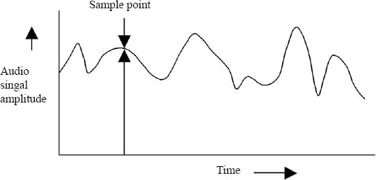
Figure 6.1. Digital Sample of an Analog Audio Signal
The sampling rate is the rate at which digital samples are made from the original material. The more often the original material is sampled, the more accurately the digital signal represents the original material.
Figure 6.2 shows an analog signal being sampled at some regular interval. Figure 6.3 shows the same analog signal being sampled twice as often. As can be seen by comparing these two figures, the more often a signal is digitally sampled, the closer the representation will be.
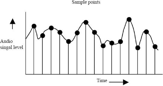
Figure 6.2. Periodic Digital Samples of an Analog Signal
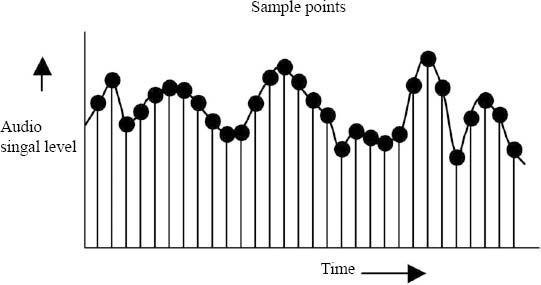
Figure 6.3. More Frequent Digital Samples of an Analog Signal
Four main sampling rates are used for digital audio: 32,000 samples per second, 44,100 samples per second, 48,000 samples per second, and 96,000 samples per second. Usually they are referred to simply as 32 kHz, 44.1 kHz, 48 kHz, and 96 kHz, respectively. Audio compact discs (CDs) have a digital sampling rate of 44.1 kHz, but most broadcast digital audio studio equipment uses 48 kHz sampling.
The audio samples are converted to a series of binary numbers, ranging from 0 to the largest binary number used for the system. For each sample, the number nearest in size to the analog amplitude is used. This is known as quantizing.
Resolution
The resolution of digital audio is the precision with which the sampled audio is measured. In other words, how accurately the digital audio numbers match the original analog material. Like many aspects of digital systems, resolution is measured in bits, because they comprise binary numbers. The higher the number of bits, the more accurately the digital signal represents the original analog material. CDs and many other items of equipment use 16 bits to represent each audio sample.
Sixteen-bit audio is not twice as accurate as 8 bit audio in replicating the original analog material: it is 256 times better. In Chapter 7, we will learn that adding one more bit to each sample number doubles the accuracy of that number; therefore, a 9 bit sample would be twice as accurate as 8 bits, and 10 bits would be twice as accurate as 9 bits. Continuing in this way, it can be seen that 16 bits is 256 times more accurate than 8 bits.
Bitstream and Bit Rate
When binary numbers representing the audio samples are sent down a wire one after the other, the stream of binary digits (bits) is referred to as a serial bitstream or usually just as a bitstream.
The bit rate necessary to transport a digital audio signal is directly related to the digital resolution of the digital audio and its sampling rate. Using the digital resolution and the sampling rate for CDs, for example, we can calculate the bit rate necessary to transport CD audio:
There are eight bits in each byte of data. So, in order to store one second of CD stereo audio on a computer disk, we need 1,411,200 ÷ 8 = 176,400 bytes of disk space. A typical three-minute song, uncompressed, would require 176,400 bytes × 180 seconds = 31.752 Megabytes of disk space. Compression techniques for reducing the bit rate and size of audio files are covered later in the book. For more on bits and bytes, see Chapter 7.
Audio A/D and D/A Converters
The process described previously is carried out in an analog-to-digital (A/D) converter. The process can be reversed in a digital-to-analog (D/A) converter, which then re-creates an analog audio waveform from the digital bitstream. These converters may be stand-alone units or may be inside other equipment.
It is common for equipment that uses digital signals internally, such as a digital audio tape (DAT) recorder, to have A/D and D/A converters inside the unit. This means that the external interfaces, or connections to the outside world, can be either digital or analog. This gives much greater flexibility in making system interconnections, which can be either analog or digital. As an example, a consumer CD player, which plays back digital audio from the disc, usually connects to a stereo system through analog left and right channel connections. However, the same player may have a digital coaxial or optical audio output, which can feed a home theater system with higher-quality digital signals. Similarly, professional digital audio equipment can usually work in either all-digital systems or as part of a mixed analog/digital environment.
Every A/D and D/A conversion introduces a small quality loss. Therefore, for highest quality, the number of conversions backward and forward between analog and digital audio should be kept to a minimum.
AES/EBU Digital Audio Distribution Standard
The AES/EBU digital audio format, also known as AES3, is a standardized format for transporting uncompressed digital audio from place to place, and is the most common standard used for this purpose. AES/EBU refers to the Audio Engineering Society and the European Broadcasting Union organizations, respectively, which together developed and published the standard.
In order to transport digital audio information, a stream of digital bits must be carried from the originating point to the receiving point. So that the device receiving the bits can understand which ones belong where, a standardized format for transporting the bits must be defined. This is what AES/EBU does. The format is able to carry two channels of audio (either two mono channels or one stereo pair), at any of the standard digital audio sampling frequencies, and with an accuracy of 16, 20, or 24 bits per sample.
The stream of digital bits is organized into 64 bit segments called frames (not to be confused with video picture frames). Each of these frames is further broken down into two subframes. Subframe 1 carries the digital audio information for audio channel 1, and subframe 2 carries the digital audio information for audio channel 2. In the vast majority of radio stations broadcasting music, the two subframes correspond to the left and right channels of the stereo audio pair. The AES/EBU frame structure is illustrated in Figure 6.4. The audio data is sent using a system called pulse code modulation (PCM), and this type of uncompressed audio is often known as linear PCM.

Figure 6.4. AES/EBU Digital Audio Frame Structure
AES/EBU signals can be carried over twisted pair or coaxial cables, or on fiber-optic cables. They may also be combined (embedded) with video signals, and may also be sent on some types of RF-based distribution systems. It is important to understand that the AES/EBU standard only defines the way digital audio is transported from one point to another, it does not define the format for audio storage, which is covered in Chapter 8.
SPDIF
Another digital interface you may come across is the Sony/Philips Digital Interface (SPDIF). This may use either coaxial or fiber-optic cables. It can carry a linear PCM AES/EBU signal, but it is also specified to carry a compressed audio bitstream such as Dolby AC-3, which may include 5.1 channel surround sound (see page 245 in Chapter 15).
Digital Signal Robustness
Digital signals are much more robust than analog and retain their quality though multiple recordings and transmission. The reason for this is that digital equipment only has to store and reproduce 0 s (low level) and 1 s (high level) for the data. It does not need to accurately reproduce all of the levels between low and high as it would for analog. To see how this works, let’s look at a recording on a digital tape machine (this applies to both audio and video, so it could be either).
Figure 6.5 shows a string of 0 s and 1 s as they might be recorded on tape, represented by high and low signal levels. So long as the tape player can distinguish between the high and low levels, the signal read off the tape will be precisely the same as the series of 0 s and 1 s that was recorded. Drawing (a) shows the digital signal with a small amount of noise, represented by the variable dark line (the tape hiss that would be heard on an analog audio tape machine). Drawing (b) shows the same signal with a much larger amount of noise—half the amplitude of the wanted signal. In an analog system, this amount of noise would be unbearable, almost drowning out the wanted signal but, as is clear from the drawing, it is still easy to detect the 0 s and 1 s and recover them perfectly. Only when the level increases greatly, as shown in the lower drawing, does it become impossible to accurately detect the digital signal, because it becomes too hard to be sure when the level is intended to be a 0 or a 1. Such digital signals, whether audio or video, are therefore much less affected by any noise introduced in a recording device or transmission path.

Figure 6.5. How a Digital Signal Relates to Noise
SD and HD Digital Video
Each line in an analog NTSC video picture is a continuous stream of video information. In contrast, each line in a digital video picture can be considered as a series of discrete pixels, derived from the words picture element. The basic principles of converting baseband analog video to digital video are in many ways similar to the digital audio conversion described previously. The analog video waveform of every line in every frame is sampled at a suitable rate and resolution, as illustrated in Figure 6.6. As with digital audio, the video samples are converted into a series of binary numbers; they are then coded in a special way, and finally produce a serial digital video bitstream.
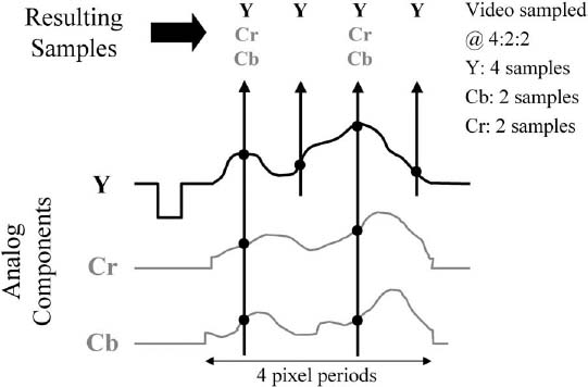
Figure 6.6. Digital Video Sampling at 4 : 2 : 2
Digital Components and Color Subsampling
Modern digital video systems sample the luminance and color difference video component signals separately, and produce digital component video signals. This allows much higher picture quality to be maintained compared to NTSC composite video. Once in the digital domain, special methods can be used to send the separate components in order, one after the other, down a single wire, thus maintaining the single-wire convenience of composite video.
As with NTSC video, the color difference signals can have their bandwidth reduced, to save on transmission and storage bandwidth. This is done by sampling the color difference signals less often than the luminance signals, and is known as chroma sub-sampling. A typical arrangement, which is shown in Figure 6.6, is 4:2:2 sampling. This means that for every four luminance samples, there are two samples for each of the color difference signals. Other arrangements include 4:1:1 and 4:2:0, where the chroma samples are reduced further in the horizontal or vertical directions; and 4:4:4, where the red, green, and blue signals are all sampled equally.
Analog video signals produced by 525-line cameras, as used for NTSC television, can be sampled and converted into digital video. This process produces one of the standard definition DTV formats. However, because the DTV transmission standard includes a method for compressing the transmitted video, it allows more video information to be squeezed into the same transmission channel size as used for analog television. This provides several opportunities for new and improved video formats that were not available with the NTSC standard. Specifically, it allows for higher resolution pictures, with wider aspect ratio and, in some cases, with higher frame rates and/or progressive scan.
The ATSC digital television standard defines 18 different picture formats for transmission (36 if the same formats using the small frame rate adjustment mentioned later are counted). Only a small number of them are usually used by broadcasters. Like NTSC video signals, all of the digital video formats end up as a rapid-fire series of still pictures that are displayed by a television receiver, but there are significant differences from NTSC video. The main characteristics of a digital video format are as follows:
• Number of active lines per picture
• Number of active pixels per line
• Frame rate
• Interlaced or progressive scan
• Picture aspect ratio
The video production formats (i.e., those used by cameras and recorders, etc.) most likely to be found in broadcast facilities are the following:
High Definition
1080 lines × 1920 pixels, 30 frames per second, interlaced, 16 : 9 aspect ratio
(usually referred to as 1080I)
1080 lines × 1920 pixels, 24 frames per second, progressive, 16 : 9 aspect ratio
(usually referred to as 1080P/24)
720 lines × 1280 pixels, 60 frames per second, progressive, 16 : 9 aspect ratio
(usually referred to as 720P)
720 lines × 1280 pixels, 24 frames per second, progressive, 16 : 9 aspect ratio
(usually referred to as 720P/24)
Standard Definition
483 lines × 720 pixels, 60 frames per second, progressive, 16 : 9 aspect ratio
483 lines × 720 pixels, 30 frames per second, interlaced, 16 : 9 aspect ratio
483 lines × 720 pixels, 30 frames per second, interlaced, 4 : 3 aspect ratio
The high definition (HD) formats have 1080 or 720 lines, and the standard definition (SD) formats all have 483 lines. The numbers of lines and pixels for the SD production formats are slightly different from those actually transmitted in ATSC DTV, but this is not significant for most purposes. The last format listed is the direct digital equivalent of analog NTSC video and is often referred to as 601 video—from the ITU (International Telecommunications Union) BT. 601 standard for 525- and 625-line digital video sampling and format.
For various reasons—mainly to do with transferring programs into different formats for distribution in different markets—there is an increasing move to produce some types of programs at 24 frames per second, the same as film rate. This frame rate is therefore common in many high definition production and postproduction facilities.
Let’s look further at these various digital video characteristics.
Lines and Pixels
These numbers largely determine the resolution of the picture (i.e., how much detail it can display and how sharp the picture looks). For digital video, the number of lines is the number of active lines in the picture (excluding the vertical blanking interval), and each line is divided up into pixels. A pixel may be considered as a dot on a video screen, the smallest component of a video image. Pixels have become familiar to most computer users because the resolution of a computer screen (i.e., the level of detail on the screen) is usually defined in terms of pixels. Some typical computer screen resolutions, defined in terms of horizontal and vertical pixels, are 640 × 480 and 1024 × 768. The more pixels there are on the screen, given a fixed monitor size, the more detailed and sharper looking the image will be. There is a trade-off, though: the larger the numbers of lines and pixels per frame, the more data is needed to transmit or store the video image.
The highest definition ATSC video format has 1080 lines on the screen. Each of these lines contains 1920 pixels, so there are about 2 million pixels in total. The standard definition ATSC video format has 483 lines, each with 720 pixels, so there are about 340,000 pixels in total. This is why it is sometimes said that high definition television is six times as sharp as standard definition. In fact, when compared to NTSC standard definition video, the difference is even greater because the analog NTSC system does not carry the full resolution of digital SD video.
Frame Rate
There are three standard frame rates for ATSC digital video: 24, 30, and 60 frames per second. Twenty-four frames per second is the rate commonly used for film, and this may be used for video carrying film-originated material or, more recently, for actual video production. Thirty frames per second is the same as the rate used for NTSC video. Sixty frames per second is a faster frame rate that improves motion rendition and reduces screen flicker by refreshing the video screen more often. The disadvantage is that the more frames per second that are transmitted, the more data that is needed to transmit or store the video signal.
All of these frame rates are used for transmission. The 30 and 24 frames per second rates with progressive scan may, in some cases, be used for production, but they are not used for display at the receiver because, as previously mentioned, the picture would flicker unacceptably. In these cases, the receiver converts these signals to either 30 frames per second interlaced or, in some cases, to 60 frames per second progressive, for display to the viewer.
At least for the duration of the transition to digital television, most television facilities will be using frame rates that are one part per thousand smaller than the integer frame rates listed previously. They do this to facilitate conversion of NTSC pictures with a frame rate of 29.97 frames per second (see page 41) to digital video for ATSC transmission and to avoid the complication of having multiple timing signals in a single facility.
Interlacing
Each of the three frame rates in ATSC video can be employed with either interlaced or progressive scanning, except that the 1920 × 1080 format is not available with 60 frames per second, progressive, and the 1280 × 720 format is available only with progressive scan.
There has been much debate over whether interlaced or progressive scanning is preferable for digital television. It is generally accepted that 60 frames per second progressive scan video produces the best motion rendition, and this has an advantage for high-motion programming such as sports. However, in the ATSC standard, the maximum resolution format possible with 60 frames per second progressive has 720 lines because, at the time the standard was developed, the bandwidth required for 1080 progressive lines at 60 frames per second was too great to be recorded or transmitted. Under critical viewing conditions, particularly with diagonal lines and/or high motion, some interlacing artifacts may be visible with 1080I. In reality, both 1080I (interlaced) and 720P (progressive) formats are capable of producing extremely high-quality pictures, and the choice of whether to use interlaced video or noninterlaced video at a broadcast facility is, to some extent, a question of personal preference.
Two picture aspect ratios, 4 : 3 and 16 : 9, as shown in Figure 6.7, are specified in the ATSC standard and are used for digital video.
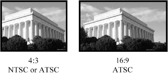
Figure 6.7. 4 : 3 and 16 : 9 Aspect Ratios
The 4:3 width to height ratio was selected because it is the same as used in NTSC video, and a tremendous number of archived television programs are in this format. The 16 : 9 ratio was selected for all high definition programming and, optionally, for standard definition. It was to some extent a compromise between the motion picture industry’s desire for as wide a screen as possible and the manufacturing costs of tube-based displays. About 80 percent of motion pictures are shot at an aspect ratio of 1.85 : 1, which easily fits into a 16 : 9 screen with negligible use of letterboxing (a technique used to fit a video image onto a television screen, without altering the aspect ratio of the original video image, by blacking out the top and bottom portions of the frame).
Bit Rates
Typical figures for sampling and bit rates of digital video in the studio are as follows:
High Definition Video
| Sampling rate: | 74.25Mhz |
| Resolution: | 10 bits |
| Samples per pixel: | 2 (average for 4:2:2 sampling) |
| Total HD bit rate: | 74.25 × 10 × 2 = 1.485 Gigabits per second |
Standard Definition Video
| Sampling rate: | 13.5MHz |
| Resolution: | 10 bits |
| Samples per pixel: | 2 (average for 4:2:2 sampling) |
| Total SD bit rate: | 13.5 × 10 × 2 = 270 Megabits per second |
Remember that, in both cases, these are the bit rates for raw, uncompressed digital video. By using compression (discussed in Chapter 15), these rates may be greatly reduced for transmission or recording.
Video A/D and D/A Converters
As with audio, the video analog-to-digital conversion processes are carried out in A/D and D/A converters, again working in either direction. As before, these may be stand-alone units or may be inside other items of equipment.
It is common for equipment that uses digital signals internally, such as a digital videotape recorder (DVTR), to have A/D and D/A converters combined with other processes inside the unit. This means that the external interfaces, or connections to the outside world, can be either digital or analog. Again, this gives much greater flexibility in making system interconnections, which can be either analog or digital. As an example, a standard definition digital VTR, which records and plays back digital video from the tape, may be incorporated into either an analog or digital video distribution system. However, modern HD video systems usually use digital distribution throughout (remember there is no such thing as a single-wire analog composite HD signal).
Every A/D and D/A conversion introduces a small quality loss. Therefore, for highest quality, the number of conversions backward and forward between analog and digital video should be kept to a minimum.
SMPTE Serial Digital Interfaces
Standards for transporting uncompressed digital video from one place to another in a broadcast studio are set by the Society of Motion Picture and Television Engineers (SMPTE), which has also developed many of the other standards on which television relies. SMPTE 259M specifies the serial digital interface (SDI) for SD video, and SMPTE 292M specifies the high definition serial digital interface (HD-SDI) for HD video.
The HD-SDI or SDI format carries the stream of digital bits representing the luminance and chrominance samples for the video. The analog sync pulses are not digitized, so special codes are added showing the start of active video (SAV) and end of active video (EAV). The luminance and chrominance data is combined together, and finally the stream of digital bits is sent sequentially down the cable. HD-SDI and SDI are similar in the way they work; the main difference is the much higher bit rate needed for HD-SDI.
Using these standards, digital video signals can be carried over coaxial cables, or over much longer distances using fiber-optic cable. They may also be sent on some types of RF-based distribution systems. It is important to understand that the SDI and HD-SDI standards only define the way digital video is transported from one point to another; they do not define the formats for storage on videotape and servers, which are covered in Chapter 9.
There are other SMPTE and DVB standards for transporting compressed video bitstreams, as mentioned in the section on bitstream distribution in Chapter 9.