
Analog Radio
In the United States, the Federal Communications Commission (FCC) regulates all radio broadcast transmissions. The FCC stipulates what standards or systems must be used and licenses stations to operate on particular frequency allocations at specific power levels. Stations within a certain distance of the borders with Canada and Mexico must also comply with related treaties and agreements made by the United States with the governments of those countries.
There is no named standard as such for basic AM and FM analog radio transmission. The modulation and transmission systems use principles and technologies that are well defined and used throughout the world. The FCC rules, however, specify various parameters, such as channels to be used, and the bandwidth (i.e., the range of frequencies) of the transmitted signal. These rules enable U.S. stations to coexist with each other and allow receivers to operate in an optimum fashion. In addition, the National Radio Systems Committee (NRSC) has developed several standards that are referenced in the FCC rules and that further define and specify the characteristics of the broadcast signal.
As discussed in Chapter 4, information is carried on a radio frequency carrier wave by modulating one or more of its characteristics. For the different types of modulation used in radio broadcasting, this chapter looks at carrier frequencies and sidebands, their relationship to channels, and the use of subcarriers to carry additional information.
In transmissions using AM—amplitude modulation—the program audio signal is used to modulate (vary) the amplitude of the carrier wave that will be transmitted by the station. When the amplitude of the program signal is zero, the carrier remains unmodulated. As the instantaneous amplitude of the program signal increases up to its maximum, then the carrier amplitude varies accordingly, up to the maximum amount possible, which is 100 percent modulation.
AM services are very susceptible to interference from outside sources of RF, such as car ignitions, electric motors, or other devices. This is because the interfering signals add or subtract from the amplitude of the wanted RF signal that carries the audio information heard at the receiver.
The limited bandwidth allocated to AM channels constrains the bandwidth of the audio signal to about 10 kHz. Most AM receivers in fact have much lower high-frequency response than this, sometimes 5 kHz or less, depending on various factors. Although this restricted bandwidth is fine for speech, music tends to sound muffled and lacking in treble. Combined with the noise and interference that may occur on AM, this means that stations wishing to broadcast high-quality music generally prefer to use FM. However, as discussed later, AM signals have the advantage that they may often be received more easily than FM over a large area, particularly at night (see Chapter 17).
Carriers and Channels for AM
The RF carrier is specified by its frequency, which for AM broadcasting is in the range of 535 to 1705 kHz in the medium frequency (MF) band. Carriers are assigned to channels, which are spaced at 10 kHz intervals in the United States (other countries use either 9 kHz or 10 kHz spacing), with the carrier frequency in the center of each channel.
In AM broadcasting, when the modulating signal (the audio program) is combined with the carrier, the varying amplitude RF signal that results is made up of the original carrier frequency and additional frequencies known as the upper and lower sidebands (see Chapter 4). For example, if the audio signal has frequencies extending to 10 kHz, then the sidebands will extend from the carrier frequency minus about 10 kHz and the carrier frequency plus about 10 kHz. This means they take up at least 20 kHz of radio spectrum. In reality, transmitters also produce additional energy in sidebands extending beyond these limits; this is sometimes referred to as splatter.
Because AM channels are allocated frequencies only 10 kHz apart, the transmission from an AM station extends into adjacent channels both above and below its allocated frequency. The maximum RF emission bandwidth allowed is specified by the FCC but, almost inevitably, first and second adjacent AM channels cannot be used in the same transmission area (factors affecting interference also include transmitted power and antenna directional characteristics).
Emissions Masks
Figure 12.1 shows the AM and FM band emissions masks defined by the FCC to protect other stations operating on nearby channels from interference. The emissions mask is the limit placed on the signal strength of the broadcast signal, and it is defined over a range of frequencies surrounding the carrier frequency. A broadcast station’s signal strength at specific frequencies must decrease as the frequencies become farther away from the carrier, and the – 25 dB (decibel) figure, as shown, defines how much the reduction must be.
As Figure 12.1 illustrates, the radio spectrum available to an AM station (about 20 kHz) for its main signal is approximately 10 percent of that available to an FM station (about 240 kHz).

Figure 12.1. Comparison of AM and FM Band Emissions Masks
Subsidiary Communications for AM
An AM station’s program material occupies all or most of the radio spectrum assigned to the station. This makes it extremely difficult to place a subcarrier for additional services in the channel, as used for FM stations (see following section).
Therefore, another method may be used for multiplexing (i.e., combining together) two signals in an AM broadcast channel. Quadrature amplitude modulation (QAM) has been used for many years as a means of allowing AM broadcasters to transmit auxiliary information on the main carrier frequency by varying another parameter of the carrier signal called phase (see Chapter 4 for more on QAM).
FM Transmission
In transmissions using FM—frequency modulation—the program audio signal is used to modulate the frequency of the carrier wave that will be transmitted by the station. When the amplitude of the program signal is zero, the carrier remains unmodulated. As the instantaneous amplitude of the program signal increases up to its maximum, then the carrier frequency varies accordingly, up to the maximum amount allowed, which is 100 percent modulation.
FM services are very robust and immune to interference from outside sources of RF. This is because, although interfering signals may add or subtract from the amplitude of the RF carrier, they do not affect the frequency of the wanted signal that carries the audio information heard at the receiver.
As mentioned previously, the bandwidth allocated to FM channels is much wider than AM, and this allows the bandwidth of the audio signal that can be transmitted to extend to about 15 kHz. This good frequency response, combined with good signal-to-noise ratio and low interference, makes FM capable of high-quality audio.
Carriers and Channels for FM
For FM broadcasting, the range of RF frequencies is 88 to 108 MHz in the very high frequency (VHF) band. Carriers are assigned to channels, which for FM are spaced at 200 kHz intervals in the United States (other countries use either 100 kHz or 200 kHz spacing), with the carrier frequency in the center of each channel.
Deviation, Sidebands, and Bandwidth
The change in frequency of the carrier, as it is modulated, is known as the deviation, or frequency swing. The maximum deviation allowed for 100 percent modulation is specified by the FCC as plus and minus 75 kHz.
Because it is the frequency, and not the amplitude, of the carrier that is varied, FM produces sidebands in a different way from AM. Without going into details, the modulating signal produces a range of upper and lower sidebands, extending much more than plus or minus 75 kHz from the carrier frequency. When using subcarriers, as discussed later, the sidebands extend out further than for mono audio alone. As Figure 12.1 illustrates, the radio spectrum available for the main signal from an FM station is specified by the FCC as plus or minus 120 kHz from the carrier frequency.
Because FM channels are allocated at 200 kHz spacing, the transmitted signal from an FM station therefore extends to some extent into adjacent channels both above and below its allocated frequency. The maximum RF emission bandwidth allowed is specified by the FCC and is reduced for much of the adjacent channels. To reduce interference, however, first adjacent FM channels are not usually allocated for use in the same transmission area.
Stereo Coding
Two-channel stereo sound, consisting of left and right program channels, is used almost universally at analog FM radio and TV broadcast stations. A system of transmitting stereo over AM was developed and incorporated into the FCC’s rules. However, because of increased potential for interference with other stations and the generally poorer audio performance of AM, the system was not widely adopted. Few AM stations these days transmit in stereo.
No matter what type of analog broadcast station is involved (FM, AM, or TV), all stereo broadcast systems use a method for coding the left and right audio channels that ensures that the stereo signal can be decoded and played by both stereophonic and monophonic receivers. It is not sufficient to simply transmit a left channel signal and a right channel signal. Instead, a “main program” channel must be transmitted that combines both the left and right audio signals together so it can be used by a monophonic receiver, and a “stereo program” channel must be transmitted that can be coupled with the main program channel to produce left and right program material at a stereo receiver.
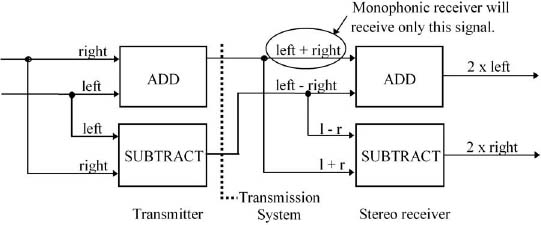
Figure 12.2. Stereo Coding
Figure 12.2 illustrates the method used to achieve this result. Before transmission, the left and right channels are added together to produce a combined mono sum signal (left + right), and the right channel signal is subtracted from the left to produce the supplementary stereo difference signal (left – right). After passing through the transmission system, the “left + right” signal can be received by mono receivers and played over a single loudspeaker. At a stereo receiver, the sum and difference signals are added together, and subtracted from each other, as follows:

This produces the original individual left and right channel signals (actually twice the amplitude, but that is easily adjusted), which can be played over stereo loudspeakers or headphones.
The stereo coding process is carried out using a stereo generator. Whether we are talking about an analog FM or TV station, the transmitter is only able to accept one audio signal to be modulated; therefore, the stereo generator has also to combine the sum and difference signals together in a special way, as described next. This system for broadcasting stereo sound is known as the Zenith system because it was developed by the Zenith Radio Corporation.
Stereo Signal Generation
In the case of FM radio, the stereo generator produces a composite output signal as shown in Figure 12.3. The “left + right” main program signal needed for mono reception is baseband audio, with 15 kHz bandwidth. A stereo pilot tone of 19 kHz is added as a reference signal, and the “left – right” stereo difference signal needed to produce the stereo channels is amplitude modulated onto the 38 kHz second harmonic of the 19 kHz stereo pilot (i.e., a subcarrier at twice the frequency). Because the stereo difference signal is an audio signal with 15 kHz bandwidth, the modulated subcarrier has lower and upper sidebands, carrying the program information, which extend 15 kHz below to 15 kHz above the suppressed 38 kHz subcarrier. This whole composite stereo signal, which is still at baseband, is fed to the FM transmitter.

Figure 12.3. Composite FM Stereo Signal
The arrangement for analog TV is similar but with a different stereo pilot frequency.
Although all combined together, these different signals do not interfere with each other because they have different frequencies. This also means that a stereo receiver can easily separate the signals out again for decoding. A mono radio receiver may not be able to separate out the stereo subcarrier signal from the mono signal, but this is not important because the stereo signal is near the top of the range of human hearing and is not reproduced by the receiver.
The stereo pilot mentioned earlier is an unmodulated subcarrier (i.e., a subcarrier that does not have any additional information added to it). One purpose of the stereo pilot is to provide a reference frequency for demodulating the stereo subcarrier. It also tells receivers that the host FM or analog TV station is broadcasting in stereo. If an FM or analog television station does not transmit the stereo pilot signal, then receivers will assume that the station is broadcasting a monaural program, and they will not try to decode the received audio into a left and right channel.
Subcarriers
As well as stereo audio, other subcarriers can be used to carry additional information in a broadcast signal, which may not be associated with the broadcaster’s main programming. The following discussion about subcarriers uses the FM baseband signal for illustrative purposes. However, this explanation of how subcarriers are added to FM signals is equally applicable to analog TV aural (sound) signals.
A subcarrier is a special type of carrier. It has similar characteristics, except that it must first be added to a host carrier before the combined signal is modulated in the transmitter in order to be delivered to a receiver. Subcarriers are common in FM radio and analog TV systems because there is plenty of room in the channel for them to be added.
Figure 12.3 illustrates the fact that an FM stereo signal actually occupies only a little more than half of the baseband spectrum that can be used. The excess channel capacity that remains presents an opportunity for FM broadcasters to generate additional income by leasing out some, or all, of their excess channel capacity to third parties for subcarrier services such as background music, radio paging, or the Radio Reading Service. The same is true for TV broadcasters, although the subcarrier space available to them is slightly different than the subcarrier space available to FM stations. The FCC refers to these as subsidiary communications authorization (SCA) services.
The three most common FM band subcarriers in use today, apart from the 38 kHz stereo subcarrier, are the 57 kHz (RDS), 67 kHz, and 92 kHz subcarriers, as shown in Figure 12.4.

Figure 12.4. FM Stereo Signal with 57 kHz (RDS), 67 kHz, and 92 kHz Subcarriers
Radio Data System
In 1993, the National Radio Systems Committee (NRSC) adopted a standard for transmitting digital data at 1187.5 bits per second on a subcarrier in the FM baseband. This standard is called the United States Radio Broadcast Data System (RBDS), often referred to as RDS, for Radio Data System. Updated editions of this standard were adopted by the NRSC in 1998 and 2004.
The RDS signal carries data such as station identification, song titles, artist names, and other program-related information; it can also accommodate other text such as weather and traffic updates. RDS data can be displayed as scrolling text on a receiver’s display panel.
The RDS subcarrier is centered on 57 kHz, the third harmonic of 19 kHz (the FM stereo pilot frequency), and the recommended bandwidth is approximately 4 kHz. As shown in Figure 12.4, the RDS signal fits between the stereo program material and the 67 kHz subcarrier.