
Radio Wave Propagation and the FCC Rules
This chapter discusses aspects of the Federal Communications Commission’s (FCC) rules that regulate broadcasting in the United States, and explains the propagation characteristics for the different broadcast frequency bands, which influence the rules for different types of stations.
FCC Rules
The FCC’s technical rules have the primary objective of ensuring that a broadcast station’s signal does not cause unacceptable amounts of interference to another broadcast station’s signal or to signals in other telecommunications services.
Another objective of the FCC rules is to ensure that the signals transmitted by the nation’s broadcasters are of good technical quality. These last objectives are met largely by requiring compliance with the various standards developed for the different types of broadcasting.
Frequency and Power Allocations
In order to ensure that stations do not interfere with one another, the FCC has adopted complex rules regarding the allocation of broadcast frequencies and power to each station. These rules are based on the propagation characteristics of the broadcast signals involved. Propagation characteristics are the particular qualities of a signal that determine how it behaves as it travels through the atmosphere (i.e., how far and in what direction).
The FCC rules and frequency allocation procedures require different broadcast signals on the same or adjacent channels to be geographically separated by appropriate distances. Different rules also require that each broadcaster’s signal must stay in its allocated part of the radio spectrum. These are the FCC’s emission masks and modulation limits, which help ensure that one station’s signal does not bleed over into the channels of other stations located next to it on the dial.
AM radio stations have distinctly different propagation characteristics from FM and TV stations, and the FCC has therefore adopted somewhat different allocation procedures for AM stations than for FM and TV. The propagation characteristics of TV and FM signals are similar, so the FCC uses a substantially similar procedure for determining whether a proposed TV or FM channel can be allocated to a particular station.
These differences of propagation are important because they affect the coverage that is achieved from a particular site, the transmitter power that is needed, and the potential interference into other stations on the same or adjacent channels. As mentioned in Chapter 4, because of their different wavelengths, the carrier waves used for AM, FM, and TV transmissions have different properties for how they propagate through the air. Let’s look at the main characteristics and also some of the considerations for digital transmissions.
AM Propagation
Skywave
What makes an AM signal so different from an FM or TV signal is the need to consider skywave propagation, which affects the MF band used for AM but not the VHF and UHF bands used for television. Skywave is a phenomenon that occurs after sunset when radio signals bounce off the ionosphere layer high in the Earth’s atmosphere, as shown in Figure 17.1.

Figure 17.1. AM Skywave Propagation
As shown in the figure, an AM signal is capable of traveling from its transmitter to a distant city, while skipping over many places in between. For this reason, care must be taken when allocating an AM frequency to a new station to ensure that the transmissions at night will not cause unacceptable levels of interference because of skywave propagation to distant AM stations on the same or adjacent channels.
Because of the need to protect other AM stations from skywave propagation, the FCC allocates some AM frequencies to stations on a daytime-only basis. These stations are generally called AM day-timers. It is also common for AM broadcasters to be granted permission to operate at night, but at a much lower power.
During the daytime, skywave propagation is not an issue for AM transmissions, because a lower layer of the Earth’s atmosphere, generated by the sun’s rays only during the daytime, absorbs upward-bound MF band AM radio waves, and the long-distance propagation disappears.
FCC rules are also intended to protect broadcast stations from each other’s groundwave signals. Although skywave propagation of AM signals occurs only at night, groundwave propagation is constant for both daytime and nighttime.
The groundwave signal, as the name implies, travels over the earth’s surface at ground level. How far the groundwave signal travels, for a given transmitter power and antenna, is largely a function of the Earth’s ground conductivity over the route being traveled by the signal. The higher the conductivity, the better the AM signal travels. Ground conductivity is a measure of the resistance of the ground to electrical signals, which varies considerably in different geographical regions, as shown in Figure 17.2, based on a map in section 73.190 of the FCC rules.
FM Propagation
There are basic differences between the way an AM groundwave and an FM signal propagate (e.g., FM VHF band radio waves do not propagate by skywave at night). The FCC’s rules for allocation of FM radio channels are, therefore, very different from the rules for AM channels. In this case, neither skywave nor groundwave propagations are issues. The main considerations are line-of-sight and distance.
Line-of-Sight Propagation
Generally speaking, as radio frequencies get higher, they become increasingly dependent on having a line-of-sight view between the transmitter and the receiver. FM band signals tend to have this characteristic, and their propagation is generally not dependent on the conductivity of the ground they are traveling over.
To understand this point, think about visible light, which has wavelengths that are much shorter than broadcast radio waves. Light has a hard time getting around any obstruction and casts a hard shadow. However, AM waves, with wavelengths in the hundreds of feet, are able to follow the surface of the earth and largely “flow” around obstacles or even mountains. FM band waves, with shorter wavelengths than AM, come somewhere in between, but they perform best in an environment with no obstructions.
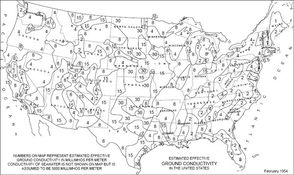
Figure 17.2. Ground Conductivity Map
The FCC’s frequency allocation procedure for FM radio stations takes into account factors including the general layout of the land around the proposed antenna site and the distance between the proposed site and other stations on the same and adjacent channels. For FM stations at the lower end of the FM band, the distance to the nearest TV channel 6 transmitter is also taken into account, because channel 6 is just below the edge of the FM band.
Multipath
Another characteristic of the shorter wavelength FM signals is their tendency to reflect off the earth’s surface when they encounter an obstruction. They will also reflect off objects such as buildings and large vehicles such as airplanes and buses (much as light reflects of shiny surfaces). Therefore, an FM transmitter located in an area where there are mountains or large hills may have major propagation problems for two reasons. First, the signal from an FM transmitter located on one side of a mountain will have a hard time reaching the other side because the mountain will block the primary signal. Also, there may be reflections off one or more hillsides, producing some transmitted energy in a different direction from that in which it was originally traveling.
This results in a phenomenon called multipath interference, which, as the name implies, occurs when FM receivers get signals, from the same FM transmitter, via more than one path. An illustration of this concept is shown in Figure 17.3. Although the two received signals are similar, they will be slightly out of phase (i.e., one of them arrives at the receiver a small fraction of a second after the other). Because of this, it is often called an echo.

Figure 17.3. Illustration of Multipath Interference
The phase difference of the two signals causes them to interfere with one another. In another example, multipath manifests itself as the “picket fencing” effect that motorists may notice on their car radios as they move slowly in a city street. The picket fencing, or repetitive noise and distortion, is caused by two or more multipath signals bouncing off buildings near the street. As the car moves, the reflected signals alternately add and subtract from the main signal, which causes the interference.
IBOC Considerations
The system design for IBOC is intended to approximately replicate the primary service area of the analog channel with the digital program service. However, the system designers acknowledged that some people listen to the analog transmissions at greater distances and lower signal strengths, accepting the increased noise and distortion that may occur. The digital service is not usually receivable at all under these conditions. Furthermore, it was considered necessary for the digital service to degrade gracefully at the edge of the service area, and for the listener not to have to suffer the “cliff effect.” Therefore, the system was provided with the capability to blend more-or-less seamlessly from the digital to the analog service at the receiver, depending on the reception conditions.
The IBOC system, using COFDM modulation, was specifically designed to resist multipath interference, which therefore does not normally cause IBOC reception to fail.
TV signals in the VHF and UHF bands propagate in basically the same manner as FM signals, but UHF signals are even more directional and dependent on line-of-sight transmission.
Multipath
Multipath interference, discussed earlier with regard to FM signals, can also cause distortion in the received audio signal from an NTSC TV station. Multipath will also cause the ghosting effect that many people will have seen at some time with their received analog TV video. Ghosting occurs when one or more video signals from the same NTSC transmitter arrive at the receiver at slightly different times. This causes additional images (ghosts) to be painted on the screen, which are displaced sideways because they are slightly delayed.
Antenna Height
An FM or TV signal is able to “see” further, and therefore propagate over longer distances, if its antenna is raised up higher. Therefore, if an antenna is raised to a new location from its originally authorized height, the FCC rules require the broadcaster to lower the station’s authorized transmitter power. Conversely, if the antenna is moved to a lower location, then the transmitter power may be increased. Such an antenna rearrangement may occur, for example, when a new DTV antenna is added to a tower, and the rules help ensure that moving the antenna does not cause new interference to other authorized stations.
ATSC DTV Considerations
ATSC (digital) pictures never display ghosts because of the way the picture is carried as digital data. As mentioned in Chapter 15, the DTV receiver is able to cancel out the unwanted echoes using circuitry called an equalizer, and the DTV signal contains special forward error correction codes that allow the receiver to correct for errors in the received signal. However, under extreme conditions with low signal strength and/or large echoes, the DTV receiver will no longer be able to correctly decode the picture (and/or the sound), and reception will fail.
Because DTV signals are more robust than NTSC, they are usually transmitted at a much lower power level than an equivalent NTSC transmission on the same channel. Although, for various reasons, replication may not occur exactly, the aim is usually for the DTV service to replicate the service area of the existing NTSC transmitter, and thus provide all viewers with the benefits of digital television.