
ATSC Digital Television
ATSC stands for the Advanced Television Systems Committee, which developed the standards for DTV used in the United States (as well as in Canada, Mexico, and Korea). The principal standards comprise ATSC documents A/53 for digital television and A/52 for AC-3 audio compression. These standards were adopted (with the exception of the video formats table) by the FCC in 1996. Other standards for different aspects of the system have since been developed. In September 2004, the FCC adopted updates to A/52 and A/53, along with A/65B, the Program and System Information Protocol Standard (PSIP). As discussed in this chapter, DTV transmission is very different from analog TV, both in the type of video and audio signals and in the way they are modulated onto the RF carrier.
ATSC DTV signals are not compatible with NTSC. In order to receive the DTV transmissions, a new type of receiver is needed—either an integrated television or a set-top box. It is possible to use a DTV set-top box to feed an existing NTSC television, but to take advantage of the improved video quality, especially high definition and widescreen images, a separate HD monitor is required.
One fundamental difference between digital ATSC and analog NTSC television is that NTSC transmits complete pictures, but the ATSC system effectively sends the pictures broken down into many small parts, with a set of instructions to put them back together again. So, what is produced and seen in the studio may or may not be exactly what all receivers produce, depending on how they interpret the instructions. This is explained later in the section on video compression.
Each NTSC station has been assigned a new channel for its ATSC DTV service. DTV RF channels are in the same VHF and UHF bands as NTSC television, using channels that were vacant in the FCC NTSC channel allocation plan. There were more vacant channels in the UHF band, so most DTV stations are in the UHF band. Changes in the FCC rules, related to spectrum recovery following the transition to DTV, mean that channels 52 to 69 will not have any digital television broadcasting at the end of the transition. In addition, some stations may move to a new DTV channel when analog broadcasting finally comes to an end.
As with NTSC, each DTV channel in the United States is 6 MHz wide. There is one carrier for each channel. A reduced-level carrier frequency, known as the pilot, is placed at the lower edge of the channel; the receiver needs this pilot carrier to help lock onto the incoming signal. Figure 15.1 shows a plot of the spectrum of an actual DTV transmission.
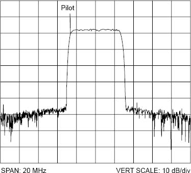
Figure 15.1. ATSC RF Channel
Channel Navigation and Branding
To make it easy for consumers to transition to the new digital channel for their favorite broadcast stations, the ATSC standard has a feature that uses the existing NTSC channel number as the major channel number for the DTV service, combined with a second minor channel number. The DTV major channel number helps the station retain its brand image. It can remain constant, even if the station has to move its DTV RF channel during the transition period. See the section on PSIP for more details.
Sidebands and Bandwidth
For reasons that are outside the scope of this book, the eight-level vestigial sideband (8-VSB) modulation used inherently produces numerous sidebands above and below the carrier frequency. To keep within the 6 MHz channel width, the upper sidebands are greatly reduced, and virtually all of the lower sidebands are cut off, leaving only a vestige of a sideband, as shown in the figure. Nevertheless, the reduced signal carries enough information to allow the data payload to be fully recovered by the receiver.
8-VSB Modulation
Digital Modulation
Eight-VSB is a special form of AM modulation using a single carrier modulated to eight different amplitude levels. The carrier is modulated with a compressed bitstream signal that, as explained later, carries all the information needed for the channel. This modulation occurs at the transmitter in a piece of equipment called an exciter (see Chapter 16 for more on exciters). The compressed bitstream input to the DTV exciter is processed and converted into digital symbols. The output of the exciter is a series of pulses of carrier wave, each with one of eight different amplitude levels that are assigned to eight symbols. These symbols are output at a rate of 10.76 million every second.
Each symbol is able to carry three bits of digital data. Therefore, the 10.76 million symbol per second output of a DTV exciter can represent 10.76 × 3 = 32.28 Mbps (megabits per second) of digital data. It is important to understand that the “data” being transmitted may represent video, audio, or other types of ancillary data information. Once in the bitstream, it is all referred to as data.
As explained in the later sections on compression and transport streams, the information bit rate for an ATSC bitstream is 19.39 Mbps. So why is the data rate coming out of a DTV exciter so much higher than the actual data rate of the video, audio, and ancillary information being broadcast? The additional bits are needed for forward error correction.
Forward Error Correction
Forward error correction (FEC) is used to make the signal more robust and able to withstand distortions in the transmission path. Multipath distortion is a common problem with over-the-air television signals, caused when multiple signals from the same transmitter arrive at the receiver at slightly different times (see Chapter 17 for more on information on multipath). There may also be various forms of interference such as lightning strikes that create large RF noise pulses, which can affect reception at great distances from the strike. Smaller RF pulses are created by electric motors, car ignition systems, and many other things. All of these conditions can cause data to be lost. The special error correction codes added to the DTV signal helps receivers to fix problems with the received signal. In addition, DTV receivers have special circuitry called adaptive equalizers to help cancel out the effects of unwanted signals.
Cliff Effect
With analog television, the received picture can be excellent (in areas of strong signal reception), mediocre, exhibiting “ghosting” and “snow” (in areas of marginal reception), or unwatchable (in areas of poor reception). ATSC DTV pictures never display ghosts because, so long as the receiver can decode the digital data that describes the picture, it can reconstruct a nearly perfect picture. However, under extreme conditions, with low received signal strength and/or strong multipath interference echoes, the DTV receiver may no longer be able to correctly decode the picture (and/or the sound). In that case, the picture and/or sound disappear completely. They go from perfect to nothing, with almost no intermediate stage. This is known as the “cliff effect,” which is common to many digital transmission technologies.
ATSC Compressed Bitstream
The ATSC compressed bitstream, comprising digital video, digital audio, and ancillary data, is known as a transport stream. This is created by the ATSC encoders and multiplexer (see Figure 9.11 in Chapter 9), and delivered to the television station’s transmitter at a rate of 19.39 Mbps. The transport stream is made up of blocks of compressed digital data, known as packets, which carry video, audio, and ancillary data. This is in contrast to the continuous stream of analog information for an NTSC signal.
The ATSC packets contain 188 bytes of data, but the first byte of each packet is used for synchronization, and an additional three packets are used for management of the bitstream, so 184 bytes are actually available for audio, video, data, and PSIP (see Figure 15.2).

Figure 15.2. ATSC Data Stream
For comparison with the 19.39 Mbps data rate of the ATSC bitstream, the fastest broadband cable Internet connection available for the home can download data at about 5 Mbps, whereas a dial-up 56 kbps modem for a personal computer has a data rate of only 0.056 Mbps.
ATSC Video Formats
Most of the characteristics of digital video signals used for ATSC transmission are discussed in Chapter 6. The signal that is actually routed around the television studio and used for editing, recording, and so on can be one of various video formats—and in fact, some stations will likely continue to use their NTSC equipment in the studio throughout the early stages of digital television implementation. In order to broadcast an ATSC DTV signal, the station must have an ATSC encoder that is capable of encoding the signal format used by the station’s studio equipment.
The video formats specified in the ATSC standard are listed in Table 15.1.
Table 15.1. ATSC Video Formats

There are 18 different formats listed. This becomes 36 if the same formats using the small frame rate adjustment mentioned in Chapter 6 are counted. The number of pixels and lines refer to those displayed in the actual picture. Horizontal and vertical blanking intervals are not transmitted in DTV, hence the VBI lines used for closed captioning, and so on in NTSC cannot be used.
You may note that the numbers of lines and pixels for the 480-line formats are slightly different from those listed as standard definition video production formats (720 × 483) in Chapter 6. The small number of extra lines and pixels have to be discarded so the picture can be broken down into the right size pieces for compression.
There is no 1920 × 1080 format at 60P (60 progressive frames per second), because the high data rate needed to transmit this format cannot be transmitted within the limited amount of bandwidth (6 MHz) available for television broadcasting in the United States. In the future, this may be achieved using more efficient compression systems than currently specified. The 1280 × 720 format does not include a 30I version (30 interlaced frames per second), because there is no existing 720-line interlaced video format with which compatibility has to be maintained.
The 704 × 480 interlaced 4 : 3 format is used to transmit programs produced as standard definition digital video, or for existing NTSC video signals converted to digital. The 640 × 480 formats were included for compatibility with the computer VGA graphics standard, but are rarely, if ever, used for DTV.
The table of video formats shown above was the one part of the ATSC DTV standard on which all parts of the industry could not agree. Hence, when the FCC incorporated the standard into its rules, the video format table was omitted completely. Broadcasters are therefore allowed to transmit any available video format. In reality, most broadcasters use the 1080-line 30I or 720-line 60P formats for high definition, and 480-line 30I for standard definition. The 24P (film rate) formats will likely see increasing use in the future because they occupy less bandwidth than other formats of the same resolution.
Video Bit Rates
As shown in Chapter 6, the total bit rate for uncompressed HD video is 1.485 Gbps, and for SD video 270 Mbps. These rates are far higher than the payload that can be transmitted in the 19.39 Mbps ATSC bitstream; therefore, it is necessary to first reduce the rate using compression.
MPEG-2 Compression
The ATSC standard is based on using MPEG-2 video compression. MPEG is the Moving Pictures Experts Group, an international standards-setting organization that has developed several standards for compressing digital video. Compression is an extremely important aspect of the ATSC system—without it, transmitting digital television would not be practical. So, what is compression?
Put simply, to compress digital video means to discard unneeded parts of the signal and encode the remaining parts in a manner that reduces the total amount of data required to store or transmit the video. All this needs to be done without noticeably degrading the picture quality. The process is performed by a powerful computer known as an MPEG-2 or ATSC encoder using a computer program called a compression algorithm. The output of the encoder is a bitstream containing packets of compressed video data. The DTV receiver has a complementary decoder, to re-create the picture quality, and the coder/decoder system is known as a codec.
The compression algorithm used for ATSC video is complex and outside the scope of this book to explain properly. We will, however, briefly discuss some of the basic principles in order to provide a general understanding of the process.
Discard Unneeded Data
The first basic principle is the elimination of all information that is not actually needed to produce the picture. Some of the data that can be discarded is the signal that occurs during the horizontal and vertical blanking periods, where there is no picture. In addition, the amount of picture color detail can be reduced without being noticeable to the human eye. In Chapter 6, we discussed chrominance subsampling; this process is done to a greater degree in video compression. In some cases, the amount of luminance (brightness) detail may also be reduced.
Exploit Redundancy
Video frames often have a great deal of redundant information that can be reduced or eliminated to decrease the amount of data that needs to be sent. A shot of a still picture is an extreme example. Instead of transmitting a stream of identical pictures 30 times per second, the DTV system could send just one complete frame of information, and then an instruction to the receiver to repeat the frame over and over, until it changes.
Even within a single frame, there may be redundancy. For example, let’s assume that a particular video image has a red horizontal line one pixel high and 100 pixels in length extending across the screen. The uncompressed video data for this image might include instructions such as the following:
Display pixel 1 in red
Display pixel 2 in red
Display pixel 3 in red
…
Display pixel 99 in red
Display pixel 100 in red
However, the compressed video data for this image could include instructions such as these:
Display pixel in red
Repeat 99 times
thus greatly reducing the amount of data while effectively sending the same information. This type of coding within a frame is called intraframe coding.
Motion Estimation and Interframe Coding
Television pictures often have an object that does not change much from frame to frame, but just moves across the screen. Often, it is possible to predict where it is heading in the next frame by looking at where it came from in the previous one; this is called motion estimation, and it provides part of the picture information that is transmitted. In addition, MPEG-2 limits the encoded information for some frames and sends only what has changed since the last picture. Exploiting the redundancy of information between different frames is called interframe coding and further reduces the amount of new information that needs to be sent to construct the next frame.
MPEG Frames
When displayed on a television receiver or monitor, ATSC video signals, like NTSC video signals, produce a rapid-fire series of still pictures, known as frames. In NTSC video, each frame is, from a technical viewpoint, identical all the way from camera to television receiver. That is, although the picture data carried changes from frame to frame, the type of frame remains constant. However, the makeup of ATSC video frames as they are transmitted is different from how they are produced in the studio and how they are displayed at the receiver. There are three distinct frame types produced by MPEG-2 compression: intracoded frames, predictive coded frames, and bidirectionally predictive coded frames. These are generally referred to as I-frames, P-frames, and B-frames.
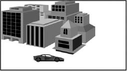
Figure 15.3. I-Frame
An I-frame is intracoded, using compression techniques only within its own borders. Thus an I-frame is a complete picture and can be decoded and displayed at a receiver by looking only at the data within itself.
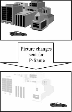
Figure 15.4. I-Frame Followed by P-Frame
A transmitted P-frame contains only the “change” information needed to re-create a video frame in conjunction with the previous I-frame that is already at the receiver. In further detail, at the decoder, the motion estimation information that accompanies a P-frame is first applied to the previous I-frame to generate a predicted frame, and then the P-frame is added to yield a complete video frame.
A transmitted B-frame contains the very small amount of “change” information needed to re-create a video frame when combined with information from two other frames, a previous I-frame or P-frame and a subsequent I-frame or P-frame. Like a P-frame, a B-frame cannot stand by itself.
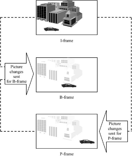
Figure 15.5. B-Frame Between an I-Frame and a P-Frame
The transmitted P- and B-frames always carry less new information than an I-frame, and therefore help reduce the data rate needed. The number and order of P- and B-frames between two I-frames is called a group of pictures (GOP) and may vary for different MPEG encoders. Long GOPs have many P- and B-frames and thus reduce the data rate best. The disadvantage of long GOPs, however, is that the extended time between I-frames slows down picture acquisition when channel surfing, and the GOP is also more susceptible to interference.
Buffering
It may seem counterintuitive that a particular frame in a video stream could be reconstructed, in part, from a future frame that has not even made it to the screen yet. How this happens is that the digital ATSC video stream does not arrive at a television set and immediately get displayed on the screen. During the decoding process, the video data is temporarily stored, processed, and then forwarded to the screen. The “store and forward” process is called buffering, a common practice in digital transmission. While the video data is temporarily stored in the receiver, the computer circuitry in the decoder has an opportunity to process or manipulate it. A similar buffer is used at the MPEG encoder so that the order in which the frames are transmitted can be changed for the particular GOP sequence being used.
As noted earlier, a B-frame is constructed with information from both previous and subsequent frames. For the receiver to be able to construct a B-frame, the two frames from which it is predicted must be transmitted before the B-frame. For example, if three frames of video have been encoded at the studio with an I-frame first, a B-frame second, and finally a P-frame, the order will be changed using the buffer in the encoder. The I-frame will then be transmitted first, followed by the P-frame and then the B-frame. The receiver can then receive and store the information for both the I-frame and the P-frame before it has to decode the B-frame.
This is a good place to point out that the buffering needed for this process is the primary reason a brief delay occurs between the instant the viewer selects a new DTV program and when the new program appears on the screen. Also contributing to this delay is the fact that, in order to begin decoding the new video stream, the decoder must wait for the next I-frame to be transmitted for that program. This is because the I-frame is the only one that can stand by itself without any previous frames to use for prediction, so in order to begin decoding a new stream of video, a receiver must start with an I-frame.
Finally, after removing the redundant information, the data that is left to send can be coded efficiently, taking advantage of the variations in the makeup of the video pixel information. An example of efficient coding is Morse code, which uses combinations of dots and dashes to transmit text messages letter by letter. The letter E typically occurs most often in the English language, so that is coded as a single dot symbol. However, an infrequently used letter, such as Q, is coded with four symbols (dash, dash, dot, dash). Thus, a typical message would be sent with more short codes and less long codes, reducing the amount of data required.
Although the type of compression used in ATSC video is much more sophisticated than described here, one can see how it is possible to code raw video data in a manner that requires less data overall to transmit but does not significantly degrade the picture. MPEG-2 is capable of reducing raw video bit rates by a factor of 60 or more.
Decoding
As described previously, during the compression process, portions of the original video stream are discarded, and the remaining portions are encoded in a manner that reduces the total amount of data to be transmitted. Although this signal that is transmitted over the air contains enough information to re-create a video image on the television screen, it does not directly carry all of the video data for each pixel of every picture. Instead, it effectively carries the instructions that enable the computer circuits inside a DTV receiver to re-create the image. The DTV receiver therefore decodes and decompresses the video data, and then reconstructs the frames of video before sending them to the display device.
Advanced Compression Systems
Recent developments in compression technology allow high-quality encoding with much greater efficiency than MPEG-2. In particular, the AVC/H.264 system (developed in conjunction with MPEG) and the VC-1 system (based on Microsoft Windows Media 9) provide equivalent picture quality at about half the bit rate or less. Such systems allow more programs to be transmitted in less bandwidth. However, because of the necessity not to make existing DTV receivers obsolete overnight, broadcasters must continue to use the MPEG-2 standard for many years to come. Various proposals are under consideration to allow the new, more efficient codecs to be used in some circumstances.
AC-3 Audio
The digital audio that accompanies ATSC video has a very different format from that used in NTSC television or traditional radio broadcasting. In particular, it has the capability for surround sound with 5.1 channels, and it is compressed to reduce its data rate for transmission.
As discussed earlier, in NTSC the video signal and the audio signal are transmitted on two separate carriers. ATSC transmission has a single signal that is a continuous stream of data packets. Each individual data packet can carry audio, video, and/or ancillary data. It is up to the ATSC receiver to sort them all out.
The packets of audio data in an ATSC signal conform to a system developed by Dolby Laboratories called AC-3 (for Audio Coding–3), which is also known as Dolby Digital. The specifications for this system are part of the ATSC standard. The system offers many improvements over NTSC audio. One of these is that noise and interference are virtually eliminated; another important feature is that it enables surround sound to be carried.
Surround Sound
AC-3 is designed to provide up to six channels of surround sound. One of these is a low frequency effects (LFE) channel that provides low-frequency audio to a subwoofer speaker that enhances audio effects, such as explosions or trains passing by. Because of the limited audio frequency range carried over the LFE channel, this channel requires much less data to convey its audio information than the other, “normal” audio channels. For this reason, the LFE channel is sometimes considered to be only one-tenth of a channel, and the overall ATSC audio system is known as a 5.1 (rather than 6) channel system.
The six channels of audio are intended to be heard through speakers that are generally positioned as shown in Figure 15.6. Because very low frequency sounds are nondirectional, the position of the low-frequency subwoofer is not critical, so this speaker can usually be positioned wherever it is most convenient.
When surround sound is not needed for a program, AC-3 can also carry regular two-channel stereo or single-channel mono signals.
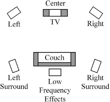
Figure 15.6. Layout of Surround Sound Speakers
In addition to the main program audio in the principal language, the ATSC system allows for one or more additional versions of the audio track to be carried with alternative languages that can be selected at the receiver.
AC-3 is also designed to allow other services to be carried simultaneously, to be selected by the viewer to supplement or replace the complete main service. These are as follows:
• Service for the visually impaired
• Service for the hearing impaired
• Associated service—dialogue
• Associated service—commentary
• Associated service—voice-over
• Main service—music and effects
• Emergency information
The Visually Impaired service is an audio channel used to describe the video scene that it accompanies. Its purpose is to allow visually impaired people to “watch” a television program by receiving periodic audio updates of the on-screen activity.
The Hearing Impaired service is an audio channel that contains dialogue that may be processed for improved intelligibility by hearing-impaired viewers. (Closed captioning information, which can also be provided for hearing-impaired viewers, is transmitted separately as video data.)
The Dialogue, Commentary, and Voice-over services were designed to be used when required with a Music and Effects service, which contains only the music and effects from the program and not any dialogue. This was intended as an alternative method to enable multiple language versions of the same program to be broadcast. Using this method, a viewer theoretically can receive the video and accompanying music and effects, and then select between the different languages available from the Dialogue, Commentary, or Voice-over services. Because of the complexity involved in creating several separate dialogue signals to accompany the same music and effects, this combination is not currently used. In any case, few, if any, DTV receivers have the two AC-3 decoders that are needed to implement this feature.
The Emergency (E) service permits the insertion of emergency messages into the audio stream. Whenever an emergency message is present, an ATSC receiver should stop playing other audio and play the emergency message. Once the emergency message has finished, the other audio will resume.
Audio Compression
If uncompressed digital 5.1 surround sound were transmitted, it would take up more than 4 Mbps of the 19.39 available bitstream data rate. The most important feature of the AC-3 system is that it allows high-quality compression of the audio signals, reducing its data rate by a factor of about 12.
AC-3, like most audio compression systems, is a perceptual coding system that relies on human psychoacoustic principles to allow certain parts of the audio signal to be discarded, or sent with less accuracy, without significantly changing the sound heard by the listener. Some of these principles include the following:
• Sounds are inaudible if they are below a certain level, which varies with frequency.
• Loud tones mask soft tones of a similar frequency occurring at the same time. In most cases, the human hearing system will not even recognize the existence of the quiet tone.
• Louder sounds mask softer sounds immediately after or before the occurrence of the louder sound. Again, they will not be heard.
Therefore, the digital bits used to represent the sounds that would not be heard anyway can be discarded without perceptibly altering the audio. After bits have been discarded, special digital coding techniques can be used to further reduce the bit rate. It is beyond the scope of this book to discuss how this is done, but one general example will give you the general idea.
Let’s say that the numerical values associated with individual digital sample points in a segment of audio are:
5, 12, 7, 9, 5, 12, 7, 9, 5, 12, 7, 9, 5, 12, 7, 9, 5, 12, 7, 9
This could be represented by simply transmitting each individual value. It is also possible, however, to transmit “5, 12, 7, 9” followed by the instruction “repeat four more times.” In this way, the amount of data necessary to transmit a long series of repetitious values can be reduced.
An AC-3 encoder uses these techniques, and other acoustical and mathematical attributes, in a sophisticated way to code raw audio data in order to reduce the data bit rate, while not significantly degrading the sound that is heard. The output of the encoder is a bitstream containing packets of compressed audio data.
Other Compression Systems
Although AC-3 is widely used for DTV, it is by no means the only compression system for audio encoding. Several other systems are widely used in radio and elsewhere. These include an earlier Dolby system called AC-2, also MPEG-1 layer 1, MPEG-1/2 layer 3 (usually known as MP3), and the more recent MPEG AAC (Advanced Audio Coding). The recent systems provide much higher audio quality at lower bit rates. There are continuing developments, and a technique called Spectral Band Replication (SBR) further improves high-frequency audio response in low-bit-rate applications.
Multiplexing
As previously mentioned, the compressed bitstream fed to the transmitter is known as a transport stream and contains video, audio, and ancillary data packets. The compressed video packets from the MPEG encoder and the compressed audio packets from the AC-3 encoder for a particular program are combined or multiplexed together to produce the transport stream. At the same time, other system information data such as PSIP (see later section) is added to the multiplex, together with ancillary data (if any) for datacasting (see later section). Figure 15.7 illustrates how the ATSC transport stream can be considered as a large data “pipe,” which is divided up into smaller “pipes” carrying multiple types of information. Don’t forget that in reality all of this information is being sent as serial data (i.e., as bits sent one after the other down a single channel).
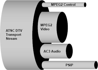
Figure 15.7. Data Pipe Concept of the ATSC Transport Stream
Quality and Bit Rates
Video Quality
There are various considerations for video quality, including the following:
• Spatial resolution (sharpness or crispness of the picture)
• Temporal resolution (how well motion is portrayed)
• Video noise (unwanted “grain” or “snow” or other interference on the screen)
• Brightness, contrast, and color accuracy
• Compression artifacts (various)
The spatial and temporal resolution of the picture is largely determined by the video format selected (number of lines, pixels, and frame rate). With DTV, there should be little, if any, degradation in these parameters caused by the transmission system. It’s the same for video noise, and distortions in brightness, contrast, and color—the picture is either perfect or not there at all.
Compression Artifacts
If insufficient bits are used to encode the video, the resulting picture exhibits degradations known as compression artifacts. The most noticeable are pixelation and blocking. When this happens, instead of natural-looking pictures, the picture breaks up instantaneously into small or larger rectangles with hard edges, either in particular areas or all over the screen. This may happen continuously or just at particular difficult events such as a dissolve, when every video pixel is changing.
No specific formula can be used to calculate exactly how many bits per second are needed to transmit a given program at a certain quality level. The data rate needed is not a constant number. It is partly dependent on the frame rate and the resolution, but it also depends very much on the subject matter of the picture. All else being equal, higher resolution, higher frame rates, and video with lots of detail and motion in it all require higher data rates.
Using MPEG-2 compression, HD video can be satisfactorily encoded at rates between about 12 and 19 Mbps, and SD video at rates from about 2 to 5 Mbps, depending on picture content. For material originally shot at 24 frames per second (film rate), the bit rate can be reduced by about 20 percent compared to 30-frame interlaced material, with similar quality.
There are various considerations for audio quality, including the following:
• Frequency response (how well high and low tones are reproduced)
• Distortion (harsh or rough-sounding audio)
• Audio Noise (unwanted “hiss” or “static”)
• Dynamic range (how well loud and soft sounds are reproduced)
• Compression artifacts (various)
The frequency response, distortion, noise levels, and dynamic range of the audio are largely determined by the audio coding system used and how well it is set up. With DTV, little, if any, degradation in these parameters should be caused by the transmission system. The audio is either perfect or not there at all.
Audio compression artifacts are not usually noticeable with a well-set-up system and are rarely objectionable. However, if too few bits are used, there may be a “swishy” or “watery” sound in the upper midrange and high-frequency areas. Another possibility is a “gritty” quality to the audio, which can sometimes be attributed to too much audio resolution being taken away in an effort to use fewer bits.
AC-3 bit rates needed for encoding audio are well established for each audio format. Typically, 5.1 audio is allocated 384 kbps, and stereo 192 kbps, although other rates can be used.
Multicasting
The total bit rate for a program service comprises the audio and video bit rates plus a small amount for system information. In many cases, a single DTV program may require less than the 19.39 Mbps available for transmission. When this occurs, it is possible to transmit multiple program services over the same DTV channel. This is done by adding additional video and audio compressed bitstreams to the multiplex and is known as multicasting.
Typically, broadcasters wanting to maintain the highest video quality do not exceed one HD program or four SD programs in the multiplex at one time. However, it is quite common to have one HD and one SD program together, or more SD channels if they include mainly static pictures, such as graphics or weather radar. Some stations may change their program mix at different times of the day, perhaps broadcasting four SD programs during the day, and switching to one HD and one SD program in the evening.
It is important that the total data rate for all of the program streams added together does not exceed the total data rate available in the DTV channel. For example, a single DTV channel might be capable of carrying four different programs most of the time. However, if these programs contain commercials that have a lot of motion and scene changes in them, the single DTV channel may not be able to handle a commercial on every single program at the same time.
Statistical Multiplexing
An important technique that can be used to help maintain the highest video quality while multicasting is called statistical multiplexing. This takes advantage of the fact that on average (i.e., statistically), different programs have different amounts of picture detail and motion at any one time. The multiplexer varies the bit rate allocated to each program on demand, to allow each one the bit rate it needs to maintain high quality. It will be rare for all programs to require maximum bits at the same time, which could result in bit starvation, causing compression artifacts.
Closed Captions
In NTSC, the information needed for carrying closed captions for the hearing impaired is carried as data on line 21 in the vertical blanking interval. The VBI lines are not encoded with MPEG compression, so in ATSC the captioning data is carried in another way. Within the video compression system, space is reserved in an area called the video user bits for carrying this additional data.
The DTV closed captioning system is specified in the Consumer Electronics Association (CEA) standard CEA-708. When this system was designed, the opportunity was taken to enhance the capabilities compared to NTSC captions. Thus, DTV captions can have a choice of fonts in different colors and sizes and at different locations on the screen, several caption services can be provided simultaneously (e.g., adding captions for different languages or for “easy reading”) and there are other enhancements.
Program and System Information Protocol (PSIP)
We have learned that ATSC DTV carries one or more program services using a digital bitstream carried in a single television RF channel. The FCC rules require broadcasters to carry Program and System Information Protocol information, usually known as PSIP, in accordance with ATSC standard A/65. This is transmitted in the multiplex with the DTV program bitstream. PSIP helps the viewer navigate to the correct program, provides an electronic program guide for current and future programs, and helps the DTV receiver tune to the correct channel and correctly decode the program.
PSIP is carried as a series of data tables that are regularly updated and carried in the DTV “pipe,” as shown conceptually in Figure 15.7 earlier in the chapter.
Major and Minor Channels
NTSC television stations in the United States have assigned call letters but typically brand themselves in a particular market using their broadcast channel number. The digital station is known by the same call letters, but with the suffix “DT” for digital television. It is, however, transmitted on a new TV channel with which viewers may not be familiar. PSIP allows the digital services to be identified with a number that relates to the well-known NTSC channel number.
PSIP includes a Virtual Channel Table (VCT) that, for terrestrial broadcasting, defines each DTV service with a two-part number consisting of a major channel followed by a minor channel. The major channel number is usually the same as the NTSC channel for the station, and the minor channels have numbers depending on how many DTV services are present in the DTV multiplex, usually starting at 1. Different arrangements, with one-part numbers, are used for ATSC services carried on cable channels. The VCT also includes the name given to each service. A station might label one service as their call letters with the suffix “HD” and, if they are multicasting, another might be labeled as SD, or some other name.
As an example, at the time of this writing, the analog channel 9 station, WUSA-TV, in Washington, D.C., identifies its two over-the-air digital services as follows:
| Channel 9-1 | WUSA-DT |
| Channel 9-2 | 9-Radar |
Minor channel number 0, if used, must indicate the NTSC program service for the station (the NTSC programs are not actually in the DTV bitstream, but they may be listed in the program guide). Services consisting only of data, with no video or audio, must use minor channel number 100 or greater.
Electronic Program Guide (EPG)
PSIP includes Event Information Tables (EITs) that provide a program schedule for each DTV program service, which allows the receiver to build and display an electronic program guide (EPG). The EITs should carry information for at least the next 9 to 12 hours of programs, and may include information up to a maximum of 16 days ahead. As well as the basic data for each program of title and start time, the information should include content advisory rating, audio format (e.g., stereo, 5.1), language, and closed caption details. Extended Text Tables (ETTs) may carry additional descriptive information about each program that may be displayed.
Directed Channel Change
Directed Channel Change (DCC) is an interesting feature that allows broadcasters to tailor programming or advertising based on viewer demographics. For example, viewers who enter location information, such as their zip code, into a DCC-equipped receiver could receive commercials that provide specific information about retail stores in their neighborhood. Segments of newscasts, such as weather alerts that are relevant to certain areas, could also be targeted based on this location information. A channel change may also be based on the program rating or the subject matter of the content of the program. Nearly 140 categories of subject matter have been defined that can be assigned to describe the content of a program. A broadcaster can use this category of DCC request switching to direct a viewer to a program based on the viewer’s desire to receive content of that subject matter.
DTV Data Broadcasting
As previously stated, the transmission system for digital television can be thought of conceptually as a large pipe for carrying the digital bitstream, which is divided up into smaller pipes for different program services. We have also learned that video and audio program material for DTV is carried as digital data—a series of bits of information. All computer systems and networks, including the Internet, use bits to process, store, and carry different types of information, whether it is a text document, a numerical spreadsheet, graphics, audio, or moving pictures. It is perhaps not surprising that, in addition to regular television programs, the DTV pipe can be used to carry these other types of digital information.
Several different standards exist for the different types of data broadcasting (also known as datacasting), both in the United States and elsewhere; details are beyond the scope of this book. It is worth noting that efforts have been made in the United States to achieve harmonization between the broadcast and cable industry in this area, and the resulting standard for broadcasting is known as the Advanced Common Application Platform (ACAP). Other data services may be carried, however, that do not comply with ACAP.
Bandwidth
The ATSC DTV pipe carries a total of about 19.39 Mbps of data, which is known as the bandwidth of the channel. As discussed previously, the amount of space needed for television video and audio depends on the number and type of programs carried. It is possible that there may be spare bandwidth, not needed for video and audio programs, and this may vary considerably at different times of day or even from instant to instant, depending on picture content.
A particular television station decides how much of its bandwidth to allocate to data broadcast services; this may be a fixed amount ranging from a few kilobits per second to several megabits per second, comparable to a high-speed broadband Internet connection.
Opportunistic Data
Even if no fixed bandwidth is allocated for datacasting, there will always be some spare bits available in the bitstream due to the variations in picture content in the television programs. These spare bits can be used for opportunistic data services that are delivered at an indeterminate data rate. This data is transmitted whenever an opportunity becomes available in the ATSC signal. For example, even if a high definition program is being transmitted, there will be times during the program when the data rate necessary to carry the video information will be reduced, such as when a still picture is on the screen. At that point, more capacity is available for data services.
Data Piping, Data Streaming, and Data Carousel
Depending on the type of datacasting service, the data required may be sent as a “package delivery” (e.g., downloading a file) or as “streaming” for continuous data delivery.
In some cases, the data may be sent repeatedly in a data carousel, which provides more opportunities for downloading the data to the receiver.
Types of Data Services
There are two basic types of datacasting service: those that are associated with a regular television program, known as program-related data, and those that stand-alone, nonprogram-related data. Examples of program-related services include the following:
• Supplementary information related to the program
• Sports statistics and additional game or player information
• Opinion polls or voting as part of a show
• Home shopping for products featured in a show
Some DTV receivers may be designed to display the additional program-related data services, inserted over the program pictures, with picture-in-picture techniques, or with separate screens, all selectable on the remote control.
Examples of nonprogram-related services include the following:
• News, weather, stock quotes
• Web pages
• Newspaper/magazine download
• Music/movies download
• Software download
Some DTV receivers may be designed to display the additional nonprogram-related data services in some manner, selectable on the remote control. However, in some cases, the data may be intended for use on a computer or some other device and will not run directly on a television.
Interactive Services
Interactive implies that the viewer interacts with the data service, sending messages to request more information or services, or to provide feedback. This may require the use of a back-channel (also known as a return-channel) that sends the viewer’s request back to the source of the service at the broadcast station or elsewhere. Digital cable television systems have the capability for a back-channel from the home built into the system, because the cable can transport information in both directions. However, since broadcasting is one-way only, over-the-air broadcasters have to provide an alternative path for the return signals. This typically uses a dial-up telephone line, although communication over the Internet is another possibility; other arrangements, using radio transmission, have been proposed.
Examples of true interactive services include quiz or game show participation, polling, or home shopping services, and any service that requires additional information to be sent from the source of the data service upon request from the viewer. However, some services that appear to be interactive do not actually require a back-channel. In that case, what happens is that all of the data that relates to a particular feature (e.g., supplementary program information) is downloaded automatically to the receiver and is already there when the viewer presses the button to display it or search for information, so the request does not need to be sent back to the source.
Conditional Access
Data services may be provided free of charge or for a fee. Conditional access systems allow broadcasters to charge for a particular service, either on a subscription basis or on a pay-per-use basis. Arrangements for this are similar to those used by cable and satellite companies for premium TV channels and pay-per-view and usually require a smart card to be used for access, with charges billed to a credit card account.
Data Broadcast Receivers
Some DTV receivers and set-top boxes are designed to display the additional program-related data services. Typically, these have additional buttons on the remote control to control and request the additional information, and the receiver has memory to store at least some of the data that is received. Other types of data services are intended to be used on a computer. Computers can have a DTV tuner added to receive such services or, in some cases, it may be possible to connect a computer to a DTV set-top box. With the convergence of technologies, the line between television and computer devices is becoming blurred, and we already have television receivers with hard disk storage. Increasingly, all such devices will have network capabilities, allowing the possibility of sharing digital media.