
MEMORY MANAGEMENT UNITS
14.1. MOVING FROM AN MPU TO AN MMU
14.2. HOW VIRTUAL MEMORY WORKS
14.4.1. Level 1 Page Table Entries
14.4.2. The L1 Translation Table Base Address
14.5. THE TRANSLATION LOOKASIDE BUFFER
14.6. DOMAINS AND MEMORY ACCESS PERMISSION
14.7. THE CACHES AND WRITE BUFFER
14.8. COPROCESSOR 15 AND MMU CONFIGURATION
14.9. THE FAST CONTEXT SWITCH EXTENSION
14.10. DEMONSTRATION: A SMALL VIRTUAL MEMORY SYSTEM
14.10.1. Step 1: Define the Fixed System Software Regions
14.10.2. Step 2: Define Virtual Memory Maps for Each Task
14.10.3. Step 3: Locate Regions in Physical Memory
14.10.4. Step 4: Define and Locate the Page Tables
14.10.5. Step 5: Define Page Table and Region Data Structures
14.10.6. Step 6: Initialize the MMU, Caches, and Write Buffer
When creating a multitasking embedded system, it makes sense to have an easy way to write, load, and run independent application tasks. Many of today’s embedded systems use an operating system instead of a custom proprietary control system to simplify this process. More advanced operating systems use a hardware-based memory management unit (MMU).
One of the key services provided by an MMU is the ability to manage tasks as independent programs running in their own private memory space. A task written to run under the control of an operating system with an MMU does not need to know the memory requirements of unrelated tasks. This simplifies the design requirements of individual tasks running under the control of an operating system.
In Chapter 13 we introduced processor cores with memory protection units. These cores have a single addressable physical memory space. The addresses generated by the processor core while running a task are used directly to access main memory, which makes it impossible for two programs to reside in main memory at the same time if they are compiled using addresses that overlap. This makes running several tasks in an embedded system difficult because each task must run in a distinct address block in main memory.
The MMU simplifies the programming of application tasks because it provides the resources needed to enable virtual memory—an additional memory space that is independent of the physical memory attached to the system. The MMU acts as a translator, which converts the addresses of programs and data that are compiled to run in virtual memory to the actual physical addresses where the programs are stored in physical main memory. This translation process allows programs to run with the same virtual addresses while being held in different locations in physical memory.
This dual view of memory results in two distinct address types: virtual addresses and physical addresses. Virtual addresses are assigned by the compiler and linker when locating a program in memory. Physical addresses are used to access the actual hardware components of main memory where the programs are physically located.
ARM provides several processor cores with integral MMU hardware that efficiently support multitasking environments using virtual memory. The goal of this chapter is to learn the basics of ARM memory management units and some basic concepts that underlie the use of virtual memory.
We begin with a review of the protection features of an MPU and then present the additional features provided by an MMU. We introduce relocation registers, which hold the conversion data to translate virtual memory addresses to physical memory addresses, and the Translation Lookaside Buffer (TLB), which is a cache of recent address relocations. We then explain the use of pages and page tables to configure the behavior of the relocation registers.
We then discuss how to create regions by configuring blocks of pages in virtual memory. We end the overview of the MMU and its support of virtual memory by showing how to manipulate the MMU and page tables to support multitasking.
Next we present the details of configuring the MMU hardware by presenting a section for each of the following components in an ARM MMU: page tables, the Translation Lookaside Buffer (TLB), access permission, caches and write buffer, the CP15:c1 control register, and the Fast Context Switch Extension (FCSE).
We end the chapter by providing demonstration software that shows how to set up an embedded system using virtual memory. The demonstration supports three tasks running in a multitasking environment and shows how to protect each task from the others running in the system by compiling the tasks to run at a common virtual memory execution address and placing them in different locations in physical memory. The key part of the demonstration is showing how to configure the MMU to translate the virtual address of a task to the physical address of a task, and how to switch between tasks.
The demonstration has been integrated into the SLOS operating system presented in Chapter 11 as a variant known as mmuSLOS.
14.1 MOVING FROM AN MPU TO AN MMU
In Chapter 13, we introduced the ARM cores with a memory protection unit (MPU). More importantly, we introduced regions as a convenient way to organize and protect memory. Regions are either active or dormant: An active region contains code or data in current use by the system; a dormant region contains code or data that is not in current use, but is likely to become active in a short time. A dormant region is protected and therefore inaccessible to the current running task.
The MPU has dedicated hardware that assigns attributes to regions. The attributes assigned to a region are shown in Table 14.1.
Table 14.1
Region attributes from the MPU example.
| Region attributes | Configuration options |
| Type | instruction, data |
| Start address | multiple of size |
| Size | 4 KB to 4 GB |
| Access permissions | read, write, execute |
| Cache | copyback, writethrough |
| Write buffer | enabled, disabled |
In this chapter, we assume the concepts introduced in Chapter 13 regarding memory protection are understood and simply show how to configure the protection hardware on an MMU.
The primary difference between an MPU and an MMU is the addition of hardware to support virtual memory. The MMU hardware also expands the number of available regions by moving the region attributes shown in Table 14.1 from CP15 registers to tables held in main memory.
14.2 HOW VIRTUAL MEMORY WORKS
In Chapter 13 we introduced the MPU and showed a multitasking embedded system that compiled and ran each task at distinctly different, fixed address areas in main memory. Each task ran in only one of the process regions, and none of the tasks could have overlapping addresses in main memory. To run a task, a protection region was placed over the fixed address program to enable access to an area of memory defined by the region. The placement of the protection region allowed the task to execute while the other tasks were protected.
In an MMU, tasks can run even if they are compiled and linked to run in regions with overlapping addresses in main memory. The support for virtual memory in the MMU enables the construction of an embedded system that has multiple virtual memory maps and a single physical memory map. Each task is provided its own virtual memory map for the purpose of compiling and linking the code and data, which make up the task. A kernel layer then manages the placement of the multiple tasks in physical memory so they have a distinct location in physical memory that is different from the virtual location it is designed to run in.
To permit tasks to have their own virtual memory map, the MMU hardware performs address relocation, translating the memory address output by the processor core before it reaches main memory. The easiest way to understand the translation process is to imagine a relocation register located in the MMU between the core and main memory.
When the processor core generates a virtual address, the MMU takes the upper bits of the virtual address and replaces them with the contents of the relocation register to create a physical address, shown in Figure 14.1
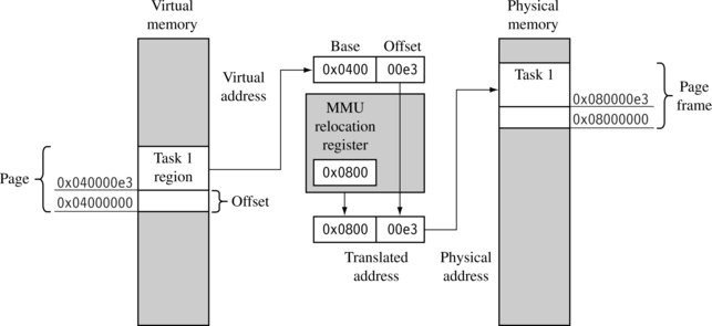
The lower portion of the virtual address is an offset that translates to a specific address in physical memory. The range of addresses that can be translated using this method is limited by the maximum size of this offset portion of the virtual address.
Figure 14.1 shows an example of a task compiled to run at a starting address of 0×4000000 in virtual memory. The relocation register translates the virtual addresses of Task 1 to physical addresses starting at 0×8000000.
A second task compiled to run at the same virtual address, in this case 0×400000, can be placed in physical memory at any other multiple of 0×10000 (64 KB) and mapped to 0×400000 simply by changing the value in the relocation register.
A single relocation register can only translate a single area of memory, which is set by the number of bits in the offset portion of the virtual address. This area of virtual memory is known as a page. The area of physical memory pointed to by the translation process is known as a page frame.
The relationship between pages, the MMU, and page frames is shown in Figure 14.2. The ARM MMU hardware has multiple relocation registers supporting the translation of virtual memory to physical memory. The MMU needs many relocation registers to effectively support virtual memory because the system must translate many pages to many page frames.
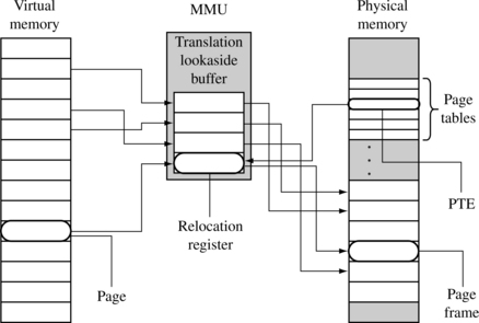
The set of relocation registers that temporarily store the translations in an ARM MMU are really a fully associative cache of 64 relocation registers. This cache is known as a Translation Lookaside Buffer (TLB). The TLB caches translations of recently accessed pages.
In addition to having relocation registers, the MMU uses tables in main memory to store the data describing the virtual memory maps used in the system. These tables of translation data are known as page tables. An entry in a page table represents all the information needed to translate a page in virtual memory to a page frame in physical memory.
A page table entry (PTE) in a page table contains the following information about a virtual page: the physical base address used to translate the virtual page to the physical page frame, the access permission assigned to the page, and the cache and write buffer configuration for the page. If you refer to Table 14.1, you can see that most of the region configuration data in an MPU is now held in a page table entry. This means access permission and cache and write buffer behavior are controlled at a granularity of the page size, which provides finer control over the use of memory. Regions in an MMU are created in software by grouping blocks of virtual pages in memory.
14.2.1 DEFINING REGIONS USING PAGES
In Chapter 13 we explained the use of regions to organize and control areas of memory used for specific functions such as task code and data, or memory input/output. In that explanation we showed regions as a hardware component of the MPU architecture. In an MMU, regions are defined as groups of page tables and are controlled completely in software as sequential pages in virtual memory.
Since a page in virtual memory has a corresponding entry in a page table, a block of virtual memory pages map to a set of sequential entries in a page table. Thus, a region can be defined as a sequential set of page table entries. The location and size of a region can be held in a software data structure while the actual translation data and attribute information is held in the page tables.
Figure 14.3 shows an example of a single task that has three regions: one for text, one for data, and a third to support the task stack. Each region in virtual memory is mapped to different areas in physical memory. In the figure, the executable code is located in flash memory, and the data and stack areas are located in RAM. This use of regions is typical of operating systems that support sharing code between tasks.
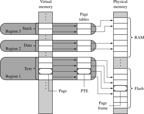
With the exception of the master level 1 (L1) page table, all page tables represent 1 MB areas of virtual memory. If a region’s size is greater than 1 MB or crosses over the 1 MB boundary addresses that separate page tables, then the description of a region must also include a list of page tables. The page tables for a region will always be derived from sequential page table entries in the master L1 page table. However, the locations of the L2 page tables in physical memory do not need to be located sequentially. Page table levels are explained more fully in Section 14.4.
14.2.2 MULTITASKING AND THE MMU
Page tables can reside in memory and not be mapped to MMU hardware. One way to build a multitasking system is to create separate sets of page tables, each mapping a unique virtual memory space for a task. To activate a task, the set of page tables for the specific task and its virtual memory space are mapped into use by the MMU. The other sets of inactive page tables represent dormant tasks. This approach allows all tasks to remain resident in physical memory and still be available immediately when a context switch occurs to activate it.
By activating different page tables during a context switch, it is possible to execute multiple tasks with overlapping virtual addresses. The MMU can relocate the execution address of a task without the need to move it in physical memory. The task’s physical memory is simply mapped into virtual memory by activating and deactivating page tables. Figure 14.4 shows three views of three tasks with their own sets of page tables running at a common execution virtual address of 0x0400000.
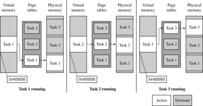
In the first view, Task 1 is running, and Task 2 and Task 3 are dormant. In the second view, Task 2 is running, and Task 1 and Task 3 are dormant. In the third view, Task 3 is running, and Task 1 and Task 2 are dormant. The virtual memory in each of the three views represents memory as seen by the running task. The view of physical memory is the same in all views because it represents the actual state of real physical memory.
The figure also shows active and dormant page tables where only the running task has an active set of page tables. The page tables for the dormant tasks remain resident in privileged physical memory and are simply not accessible to the running task. The result is that dormant tasks are fully protected from the active task because there is no mapping to the dormant tasks from virtual memory.
When the page tables are activated or deactivated, the virtual-to-physical address mappings change. Thus, accessing an address in virtual memory may suddenly translate to a different address in physical memory after the activation of a page table. As mentioned in Chapter 12, the ARM processor cores have a logical cache and store cached data in virtual memory. When this translation occurs, the caches will likely contain invalid virtual data from the old page table mapping. To ensure memory coherency, the caches may need cleaning and flushing. The TLB may also need flushing because it will have cached old translation data.
The effect of cleaning and flushing the caches and the TLB will slow system operation. However, cleaning and flushing stale code or data from cache and stale translated physical addresses from the TLB keep the system from using invalid data and breaking.
During a context switch, page table data is not moved in physical memory; only pointers to the locations of the page tables change.
To switch between tasks requires the following steps:
1. Save the active task context and place the task in a dormant state.
2. Flush the caches; possibly clean the D-cache if using a writeback policy.
3. Flush the TLB to remove translations for the retiring task.
4. Configure the MMU to use new page tables translating the virtual memory execution area to the awakening task’s location in physical memory.
Note: to reduce the time it takes to perform a context switch, a writethrough cache policy can be used in the ARM9 family. Cleaning the data cache can require hundreds of writes to CP15 registers. By configuring the data cache to use a writethrough policy, there is no need to clean the data cache during a context switch, which will provide better context switch performance. Using a writethrough policy distributes these writes over the life of the task. Although a writeback policy will provide better overall performance, it is simply easier to write code for small embedded systems using a writethrough policy.
This simplification applies because most systems use flash memory for nonvolatile storage, and copy programs to RAM during system operation. If your system has a file system and uses dynamic paging then it is time to switch to a write-back policy because the access time to file system storage are tens to hundreds of thousands of times slower than access to RAM memory.
If, after some performance analysis, the efficiency of a writethrough system is not adequate, then performance can be improved using a writeback cache. If you are using a disk drive or other very slow secondary storage, a writeback policy is almost mandatory.
This argument only applies to ARM cores that use logical caches. If a physical cache is present, as in the ARM11 family, the information in cache remains valid when the MMU changes its virtual memory map. Using a physical cache eliminates the need to perform cache management activities when changing virtual memory addresses. For further information on caches, refer to Chapter 12.
14.2.3 MEMORY ORGANIZATION IN A VIRTUAL MEMORY SYSTEM
Typically, page tables reside in an area of main memory where the virtual-to-physical address mapping is fixed. By “fixed,” we mean data in a page table doesn’t change during normal operation, as shown in Figure 14.5. This fixed area of memory also contains the operating system kernel and other processes. The MMU, which includes the TLB shown in Figure 14.5, is hardware that operates outside the virtual or physical memory space; its function is to translate addresses between the two memory spaces.
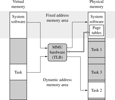
The advantage of this fixed mapping is seen during a context switch. Placing system software at a fixed virtual memory location eliminates some memory management tasks and the pipeline effects that result if a processor is executing in a region of virtual memory that is suddenly remapped to a different location in physical memory.
When a context switch occurs between two application tasks, the processor in reality makes many context switches. It changes from a user mode task to a kernel mode task to perform the actual movement of context data in preparation for running the next application task. It then changes from the kernel mode task to the new user mode task of the next context.
By sharing the system software in a fixed area of virtual memory that is seen across all user tasks, a system call can branch directly to the system area and not worry about needing to change page tables to map in a kernel process. Making the kernel code and data map to the same virtual address in all tasks eliminates the need to change the memory map and the need to have an independent kernel process that consumes a time slice.
Branching to a fixed kernel memory area also eliminates an artifact inherent in the pipeline architecture. If the processor core is executing code in a memory area that changes addresses, the core will have prefetched several instructions from the old physical memory space, which will be executed as the new instructions fill the pipeline from the newly mapped memory space. Unless special care is taken, executing the instructions still in the pipeline from the old memory map may corrupt program execution.
We recommend activating page tables while executing system code at a fixed address region where the virtual-to-physical memory mapping never changes. This approach ensures a safe switch between user tasks.
Many embedded systems do not use complex virtual memory but simply create a “fixed” virtual memory map to consolidate the use of physical memory. These systems usually collect blocks of physical memory spread over a large address space into a contiguous block of virtual memory. They commonly create a “fixed” map during the initialization process, and the map remains the same during system operation.
14.3 DETAILS OF THE ARM MMU
The ARM MMU performs several tasks: It translates virtual addresses into physical addresses, it controls memory access permission, and it determines the individual behavior of the cache and write buffer for each page in memory. When the MMU is disabled, all virtual addresses map one-to-one to the same physical address. If the MMU is unable to translate an address, it generates an abort exception. The MMU will only abort on translation, permission, and domain faults.
The main software configuration and control components in the MMU are
We provide the details of operation and how to configure these components in the following sections.
14.4 PAGE TABLES
The ARM MMU hardware has a multilevel page table architecture. There are two levels of page table: level 1 (L1) and level 2 (L2).
There is a single level 1 page table known as the L1 master page table that can contain two types of page table entry. It can hold pointers to the starting address of level 2 page tables, and page table entries for translating 1 MB pages. The L1 master table is also known as a section page table.
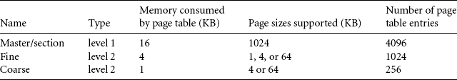
The master L1 page table divides the 4 GB address space into 1 MB sections; hence the L1 page table contains 4096 page table entries. The master table is a hybrid table that acts as both a page directory of L2 page tables and a page table translating 1 MB virtual pages called sections. If the L1 table is acting as a directory, then the PTE contains a pointer to either an L2 coarse or L2 fine page table that represents 1 MB of virtual memory. If the L1 master table is translating a 1 MB section, then the PTE contains the base address of the 1 MB page frame in physical memory. The directory entries and 1 MB section entries can coexist in the master page table.
A coarse L2 page table has 256 entries consuming 1 KB of main memory. Each PTE in a coarse page table translates a 4 KB block of virtual memory to a 4 KB block in physical memory. A coarse page table supports either 4 or 64 KB pages. The PTE in a coarse page contains the base address to either a 4 or 64 KB page frame; if the entry translates a 64 KB page, an identical PTE must be repeated in the page table 16 times for each 64 KB page.
A fine page table has 1024 entries consuming 4 KB of main memory. Each PTE in a fine page translates a 1 KB block of memory. A fine page table supports 1, 4, or 64 KB pages in virtual memory. These entries contain the base address of a 1, 4, or 64 KB page frame in physical memory. If the fine table translates a 4 KB page, then the same PTE must be repeated 4 consecutive times in the page table. If the table translates a 64 KB page, then the same PTE must be repeated 64 consecutive times in the page table.
Table 14.2 summarizes the characteristics of the three kinds of page table used in ARM memory management units.
14.4.1 LEVEL 1 PAGE TABLE ENTRIES
The level 1 page table accepts four types of entry:
![]() A 1 MB section translation entry
A 1 MB section translation entry
![]() A directory entry that points to a fine L2 page table
A directory entry that points to a fine L2 page table
The system identifies the type of entry by the lower two bits [1:0] in the entry field. The format of the PTE requires the address of an L2 page table to be aligned on a multiple of its page size. Figure 14.6 shows the format of each entry in the L1 page table.
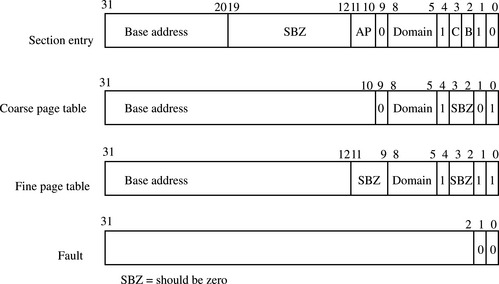
A section page table entry points to a 1 MB section of memory. The upper 12 bits of the page table entry replace the upper 12 bits of the virtual address to generate the physical address. A section entry also contains the domain, cached, buffered, and access permission attributes, which we discuss in Section 14.6.
A coarse page entry contains a pointer to the base address of a second-level coarse page table. The coarse page table entry also contains domain information for the 1 MB section of virtual memory represented by the L1 table entry. For coarse pages, the tables must be aligned on an address multiple of 1 KB.
A fine page table entry contains a pointer to the base address of a second-level fine page table. The fine page table entry also contains domain information for the 1 MB section of virtual memory represented by the L1 table entry. Fine page tables must be aligned on an address multiple of 4 KB.
A fault page table entry generates a memory page fault. The fault condition results in either a prefetch or data abort, depending on the type of memory access attempted.
The location of the L1 master page table in memory is set by writing to the CP15:c2 register.
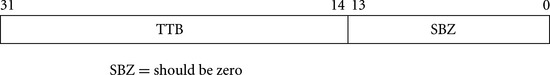
14.4.2 THE L1 TRANSLATION TABLE BASE ADDRESS
The CP15:c2 register holds the translation table base address (TTB)—an address pointing to the location of the master L1 table in virtual memory. Figure 14.7 shows the format of CP15:c2 register.
EXAMPLE 14.1
Here is a routine named ttbSet that sets the TTB of the master L1 page table. The ttbSet routine uses an MRC instruction to write to CP15:c2:c0:0. The routine is defined using the following function prototype:
![]()
The only argument passed to the procedure is the base address of the translation table. The TTB address must be aligned on a 16 KB boundary in memory.
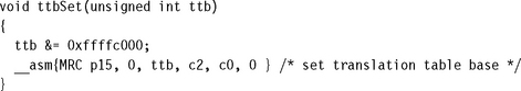
14.4.3 LEVEL 2 PAGE TABLE ENTRIES
There are four possible entries used in L2 page tables:
![]() A large page entry defines the attributes for a 64 KB page frame.
A large page entry defines the attributes for a 64 KB page frame.
![]() A small page entry defines a 4 KB page frame.
A small page entry defines a 4 KB page frame.
![]() A tiny page entry defines a 1 KB page frame.
A tiny page entry defines a 1 KB page frame.
![]() A fault page entry generates a page fault abort exception when accessed.
A fault page entry generates a page fault abort exception when accessed.
Figure 14.8 shows the format of the entries in an L2 page table. The MMU identifies the type of L2 page table entry by the value in the lower two bits of the entry field.
A large PTE includes the base address of a 64 KB block of physical memory. The entry also has four sets of permission bit fields, as well as the cache and write buffer attributes for the page. Each set of access permission bit fields represents one-fourth of the page in virtual memory. These entries maybe thought of as 16 KB subpages providing finer control of access permission within the 64 KB page.
A small PTE holds the base address of a 4 KB block of physical memory. The entry also includes four sets of permission bit fields and the cache and write buffer attributes for the page. Each set of permission bit fields represents one-fourth of the page in virtual memory. These entries maybe thought of as 1 KB subpages providing finer control of access permission within the 4 KB page.
A tiny PTE provides the base address of a 1 KB block of physical memory. The entry also includes a single access permission bit field and the cache and write buffer attributes for the page. The tiny page has not been incorporated in the ARMv6 architecture. If you are planning to create a system that is easily portable to future architectures, we recommend avoiding the use of tiny 1 KB pages in your system.
A fault PTE generates a memory page access fault. The fault condition results in either a prefetch or data abort, depending on the type of memory access.
14.4.4 SELECTING A PAGE SIZE FOR YOUR EMBEDDED SYSTEM
Here are some tips and suggestions for setting the page size in your system:
![]() The smaller the page size, the more page frames there will be in a given block of physical memory.
The smaller the page size, the more page frames there will be in a given block of physical memory.
![]() The smaller the page size, the less the internal fragmentation. Internal fragmentation is the unused memory area in a page. For example, a task 9 KB in size can fit in three 4 KB pages or one 64 KB page. In the first case, using 4 KB pages, there are 3 KB of unused space. In the case using 64 KB pages, there are 55 KB of unused page space.
The smaller the page size, the less the internal fragmentation. Internal fragmentation is the unused memory area in a page. For example, a task 9 KB in size can fit in three 4 KB pages or one 64 KB page. In the first case, using 4 KB pages, there are 3 KB of unused space. In the case using 64 KB pages, there are 55 KB of unused page space.
![]() The larger the page size, the more likely the system will load referenced code and data.
The larger the page size, the more likely the system will load referenced code and data.
![]() Large pages are more efficient as the access time to secondary storage increases.
Large pages are more efficient as the access time to secondary storage increases.
![]() As the page size increases, each TLB entry represents more area in memory. Thus, the system can cache more translation data, and the faster the TLB is loaded with all translation data for a task.
As the page size increases, each TLB entry represents more area in memory. Thus, the system can cache more translation data, and the faster the TLB is loaded with all translation data for a task.
![]() Each page table consumes 1 KB of memory if you use L2 coarse pages. Each L2 fine page table consumes 4 KB. Each L2 page table translates 1 MB of address space. Your maximum page table memory use, per task, is
Each page table consumes 1 KB of memory if you use L2 coarse pages. Each L2 fine page table consumes 4 KB. Each L2 page table translates 1 MB of address space. Your maximum page table memory use, per task, is
14.5 THE TRANSLATION LOOKASIDE BUFFER
The TLB is a special cache of recently used page translations. The TLB maps a virtual page to an active page frame and stores control data restricting access to the page. The TLB is a cache and therefore has a victim pointer and a TLB line replacement policy. In ARM processor cores the TLB uses a round-robin algorithm to select which relocation register to replace on a TLB miss.
The TLB in ARM processor cores does not have many software commands available to control its operation. The TLB supports two types of commands: you can flush the TLB, and you can lock translations in the TLB.
During a memory access, the MMU compares a portion of the virtual address to all the values cached in the TLB. If the requested translation is available, it is a TLB hit, and the TLB provides the translation of the physical address.
If the TLB does not contain a valid translation, it is a TLB miss. The MMU automatically handles TLB misses in hardware by searching the page tables in main memory for valid translations and loading them into one of the 64 lines in the TLB. The search for valid translations in the page tables is known as a page table walk. If there is a valid PTE, the hardware copies the translation address from the PTE to the TLB and generates the physical address to access main memory. If, at the end of the search, there is a fault entry in the page table, then the MMU hardware generates an abort exception.
During a TLB miss, the MMU may search up to two page tables before loading data to the TLB and generating the needed address translation. The cost of a miss is generally one or two main memory access cycles as the MMU translation table hardware searches the page tables. The number of cycles depends on which page table the translation data is found in. A single-stage page table walk occurs if the search ends with the L1 master page table; there is a two-stage page table walk if the search ends with an L2 page table.
A TLB miss may take many extra cycles if the MMU generates an abort exception. The extra cycles result as the abort handler maps in the requested virtual memory. The ARM720T has a single TLB because it has a unified bus architecture. The ARM920T, ARM922T, ARM926EJ-S, and ARM1026EJ-S have two Translation Lookaside Buffers because they use a Harvard bus architecture: one TLB for instruction translation and one TLB for data translation.
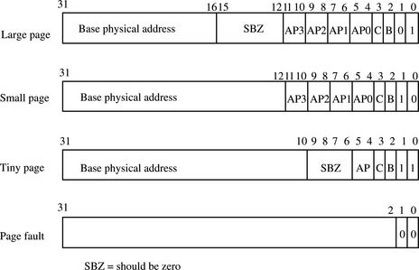
14.5.1 SINGLE-STEP PAGE TABLE WALK
If the MMU is searching for a 1 MB section page, then the hardware can find the entry in a single-step search because 1 MB page table entries are found in the master L1 page table.
Figure 14.9 shows the table walk of an L1 table for a 1 MB section page translation. The MMU uses the base portion of the virtual address, bits [31:20], to select one of the 4096 entries in the L1 master page table. If the value in bits [1:0] is binary 10, then the PTE has a valid 1 MB page available. The data in the PTE is transferred to the TLB, and the physical address is translated by combining it with the offset portion of the virtual address.
If the lower two bits are 00, then a fault is generated. If it is either of the other two values, the MMU performs a two-stage search.
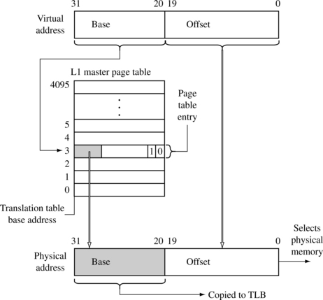
14.5.2 TWO-STEP PAGE TABLE WALK
If the MMU ends its search for a page that is 1, 4, 16, or 64 KB in size, then the page table walk will have taken two steps to find the address translation. Figure 14.10 details the two-stage process for a translation held in a coarse L2 page table. Note that the virtual address is divided into three parts.
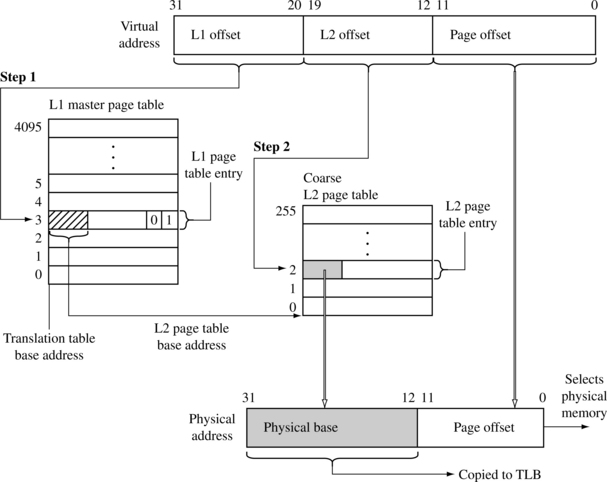
Figure 14.10 Two-level virtual-to-physical address translation using coarse page tables and 4 KB pages.
In the first step, the L1 offset portion is used to index into the master L1 page table and find the L1 PTE for the virtual address. If the lower two bits of the PTE contain the binary value 01, then the entry contains the L2 page table base address to a coarse page (see Figure 14.6).
In the second step, the L2 offset is combined with the L2 page table base address found in the first stage; the resulting address selects the PTE that contains the translation for the page. The MMU transfers the data in the L2 PTE to the TLB, and the base address is combined with the offset portion of the virtual address to generate the requested address in physical memory.
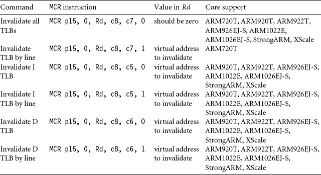
14.5.3 TLB OPERATIONS
If the operating system changes data in the page tables, translation data cached in the TLB may no longer be valid. To invalidate data in the TLB, the core has CP15 commands to flush the TLB. There are several commands available (see Table 14.3): one to flush all TLB data, one to flush the Instruction TLB, and another to flush the Data TLB. The TLB can also be flushed a line at a time.
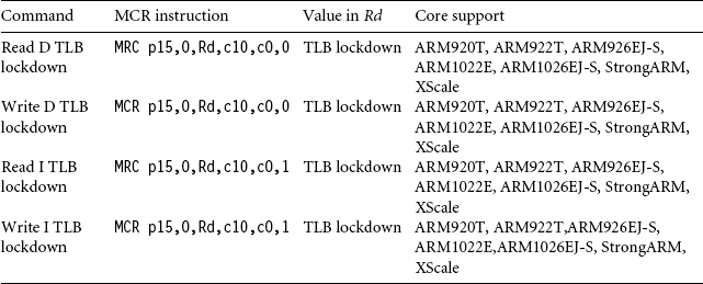
14.5.4 TLB LOCKDOWN
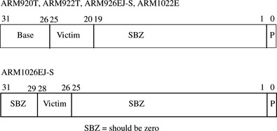
The ARM920T, ARM922T, ARM926EJ-S, ARM1022E, and ARM1026EJ-S support locking translations in the TLB. If a line is locked in the TLB, it remains in the TLB when a TLB flush command is issued. We list the available lockdown commands for the various ARM cores in Table 14.4. The format of the core register Rd used in the MCR instruction that locks data in the TLB in shown in Figure 14.11.
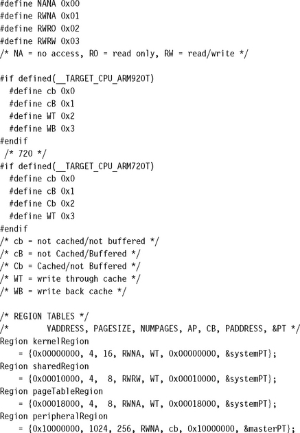
14.6 DOMAINS AND MEMORY ACCESS PERMISSION
There are two different controls to manage a task’s access permission to memory: The primary control is the domain, and a secondary control is the access permission set in the page tables.
Domains control basic access to virtual memory by isolating one area of memory from another when sharing a common virtual memory map. There are 16 different domains that can be assigned to 1 MB sections of virtual memory and are assigned to a section by setting the domain bit field in the master L1 PTE (see Figure 14.6).
When a domain is assigned to a section, it must obey the domain access rights assigned to the domain. Domain access rights are assigned in the CP15:c3 register and control the processor core’s ability to access sections of virtual memory.
The CP15:c3 register uses two bits for each domain to define the access permitted for each of the 16 available domains. Table 14.5 shows the value and meaning of a domain access bit field. Figure 14.12 gives the format of the CP15:c3:c0 register, which holds the domain access control information. The 16 available domains are labeled from D0 to D15 in the figure.
Table 14.5
Domain access bit assignments.
| Access | Bit field value | Comments |
| Manager | 11 | access is uncontrolled, no permission aborts generated |
| Reserved | 10 | unpredictable |
| Client | 01 | access controlled by permission values set in PTE |
| No access | 00 | generates a domain fault |
Even if you don’t use the virtual memory capabilities provided by the MMU, you can still use these cores as simple memory protection units: first, by mapping virtual memory directly to physical memory, assigning a different domain to each task, then using domains to protect dormant tasks by assigning their domain access to “no access.”
14.6.1 PAGE-TABLE-BASED ACCESS PERMISSIONS
The AP bits in a PTE determine the access permission for a page. The AP bits are shown in Figures 14.6 and 14.8. Table 14.6 shows how the MMU interprets the two bits in the AP bit field.
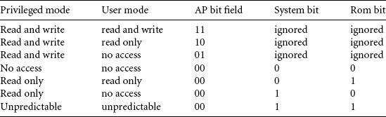
In addition to the AP bits located in the PTE, there are two bits in the CP15:c1 control register that act globally to modify access permission to memory: the system (S) bit and the rom (R) bit. These bits can be used to reveal large blocks of memory from the system at different times during operation.
Setting the S bit changes all pages with “no access” permission to allow read access for privileged mode tasks. Thus, by changing a single bit in CP15:c1, all areas marked as no access are instantly available without the cost of changing every AP bit field in every PTE.
Changing the R bit changes all pages with “no access” permission to allow read access for both privileged and user mode tasks. Again, this bit can speed access to large blocks of memory without needing to change lots of PTEs.
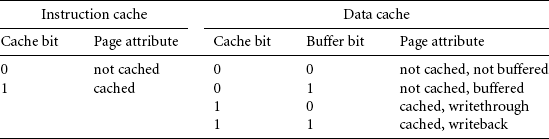
14.7 THE CACHES AND WRITE BUFFER
We presented the basic operation of caches and write buffers in Chapter 12. You configure the caches and write buffer for each page in memory using two bits in a PTE (see Figures 14.6 and 14.8). When configuring a page of instructions, the write buffer bit is ignored and the cache bit determines cache operation. When the bit is set, the page is cached, and when the bit is clear, the page is not cached.
When configuring data pages, the write buffer bit has two uses: it enables or disables the write buffer for a page, and it sets the page cache write policy. The page cache bit controls the meaning of the write buffer bit. When the cache bit is zero, the buffer bit enables the write buffer when the buffer bit value is one, and disables the write buffer when the buffer bit value is zero. When the cache bit is set to one, the write buffer is enabled, and the state of the buffer bit determines the cache write policy. The page uses a writethrough policy if the buffer bit is zero and a writeback policy if the buffer bit is set; refer to Table 14.7, which gives a tabular view of the various states of the cache and write buffer bits and their meaning.
14.8 COPROCESSOR 15 AND MMU CONFIGURATION
We first introduced the procedure changeControl in Chapter 12. Example 14.3 revisits the procedure changeControl, which we use to enable the MMU, caches, and write buffer.
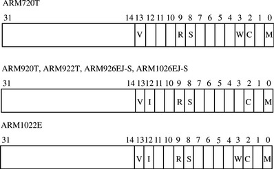
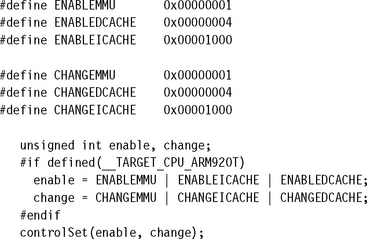
The control register values that control MMU operation are shown in Table 14.8 and Figure 14.13. The ARM720T, ARM920T, and the ARM926EJ-S all have the MMU enable bit[0] and cache enable bit[2] in the same location in the control register. The ARM720T and ARM1022E have a write buffer enable, bit[3]. The ARM920T, ARM922T, and ARM926EJS have split instruction and data caches, requiring an extra bit to enable the I-cache, bit[12]. All processor cores with an MMU support changing the vector table to high memory at address 0×ffff0000, bit[13].
Table 14.8
Description of the bit fields in the control register CP15:c1 that control MMU operation.
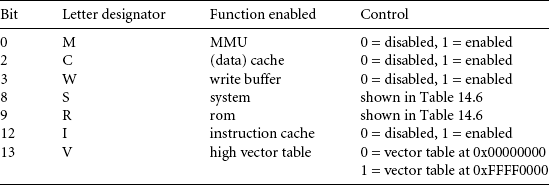
Enabling a configured MMU is very similar for the three cores. To enable the MMU, caches, and write buffer, you need to change bit[12], bit[3], bit[2], and bit[0] in the control register.
The procedure, changeControl, operates on register CP15:c1:c0:0 to change the values in the control register c1. Example 14.3 gives a small C routine that sets bits in the control register; it is called using the following function prototype:
![]()
The first parameter passed to the procedure is an unsigned integer containing the state of the control values you want to change. The second parameter, mask, is a bit pattern that selects the bits that need changing. A bit set to one in the mask variable changes the bit in the CP15:c1c0 register to the value of the same bit in the value input parameter. A zero leaves the bit in the control register unchanged, regardless of the bit state in the value parameter.
EXAMPLE 14.3
The routine controlSet sets the control bits register in CP15:c1. The routine first reads the CP15:r3 register and places it in the variable c1format. The routine then uses the input mask value to clear the bits in c1format that need updating. The update is done by ORing c1format with the value input parameter. The updated c1format is finally written back out to the CP15:c1 register to enable the MMU, caches, and write buffer.
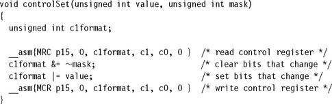
Here is a code sequence that calls the controlSet routine to enable the I-cache, D-cache, and the MMU in an ARM920T:
14.9 THE FAST CONTEXT SWITCH EXTENSION
The Fast Context Switch Extension (FCSE) is additional hardware in the MMU that is considered an enhancement feature, which can improve system performance in an ARM embedded system. The FCSE enables multiple independent tasks to run in a fixed overlapping area of memory without the need to clean or flush the cache, or flush the TLB during a context switch. The key feature of the FCSE is the elimination of the need to flush the cache and TLB.
Without the FCSE, switching from one task to the next requires a change in virtual memory maps. If the change involves two tasks with overlapping address ranges, the information stored in the caches and TLB become invalid, and the system must flush the caches and TLB. The process of flushing these components adds considerable time to the task switch because the core must not only clear the caches and TLB of invalid data, but it must also reload data to the caches and TLB from main memory.
With the FCSE there is an additional address translation when managing virtual memory. The FCSE modifies virtual addresses before it reaches the cache and TLB using a special relocation register that contains a value known as the process ID. ARM refers to the addresses in virtual memory before the first translation as a virtual address (VA), and those addresses after the first translation as a modified virtual address(MVA), shown in Figure 14.4. When using the FCSE, all modified virtual addresses are active. Tasks are protected by using the domain access facilities to block access to dormant tasks. We discuss this in more detail in the next section.
Switching between tasks does not involve changing page tables; it simply requires writing the new task’s process ID into the FCSE process ID register located in CP15. Because a task switch does not require changing the page tables, the caches and TLB remain valid after the switch and do not need flushing.
When using the FCSE, each task must execute in the fixed virtual address range from 0x00000000 to 0x1FFFFFFF and must be located in a different 32 MB area of modified virtual memory. The system shares all memory addresses above 0x2000000, and uses domains to protect tasks from each other. The running task is identified by its current process ID.
To utilize the FCSE, compile and link all tasks to run in the first 32 MB block of virtual memory (VA) and assign a unique process ID. Then place each task in a different 32 MB partition of modified virtual memory using the following relocation formula:
To calculate the starting address of a task partition in modified virtual memory, take a value of zero for the VA and the task’s process ID, and use these values in Equation (14.2).
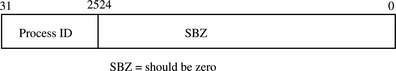
The value held in the CP15:c13:c0 register contains the current process ID. The process ID bit field in the register is seven bits wide and supports 128 process IDs. The format of the register is shown in Figure 14.15.
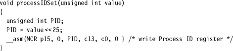
Example 14.4 shows a small routine processIDSet that sets the process ID in the FCSE. It can be called using the following function prototype:
![]()
EXAMPLE 14.4
This routine takes an unsigned integer as an input, clips it to seven bits, mod 128, by multiplying the value by 0×20000000 (32 MB), and then writing the result to the process ID register using an MCR instruction.
14.9.1 HOW THE FCSE USES PAGE TABLES AND DOMAINS
To use the FCSE efficiently, the system uses page tables to control region configuration and operation, and domains to isolate tasks from each other. Refer again to Figure 14.14, which shows the memory layout before and after a context switch from Task 1 to Task 2. Table 14.9 shows the numerical details used to create Figure 14.14.
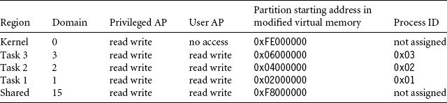

Figure 14.14 Fast Context Switch Extension example showing task 1 before a context switch and task 2 running after a context switch in a three-task multitasking environment.
Figure 14.16 shows how to change the value in the domain access register of CP15:c3:c0 to switch from Task 1 to Task 2. Switching between tasks requires a change in the process ID and a new entry in the domain access register.
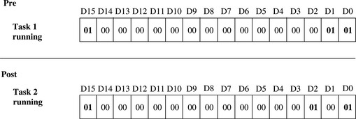
Figure 14.16 Pre- and post-view of CP15 register 3 changing from Task 1 to Task 2 in a three-task multiprogramming environment.
Table 14.9 shows that Task 1 is assigned Domain 1, and Task 2 is assigned Domain 2. When changing from Task 1 to Task 2, change the domain access register to allow client access to Domain 2, and no access to Domain 1. This prevents Task 2 from accessing the memory space of Task 1. Note that client access remains the same for the kernel, Domain 0. This allows the page tables to control access to the system area of memory.
Sharing memory between tasks can be accomplished by using a “sharing” domain, shown as Domain 15 in Figure 14.16 and Table 14.9. The sharing domain is not shown in Figure 14.15. Tasks can share a domain that allows client access to a partition in modified virtual memory. This shared memory can be seen by both tasks, and access is determined by the page table entries that map the memory space.
Here are the steps needed to perform a context switch when using the FCSE:
14.9.2 HINTS FOR USING THE FCSE
![]() A task has a fixed 32 MB maximum limit on size.
A task has a fixed 32 MB maximum limit on size.
![]() The memory manager must use fixed 32 MB partitions with a fixed starting address that is a multiple of 32 MB.
The memory manager must use fixed 32 MB partitions with a fixed starting address that is a multiple of 32 MB.
![]() Unless you want to manage an exception vector table for each task, place the exception vector table at virtual address 0xffff0000, using the V bit in CP15 register 1.
Unless you want to manage an exception vector table for each task, place the exception vector table at virtual address 0xffff0000, using the V bit in CP15 register 1.
![]() You must define and use an active domain control system.
You must define and use an active domain control system.
![]() The core fetches the two instructions following a change in process ID from the previous process space, if execution is taking place in the first 32 MB block. Therefore, it is wise to switch tasks from a “fixed” region in memory.
The core fetches the two instructions following a change in process ID from the previous process space, if execution is taking place in the first 32 MB block. Therefore, it is wise to switch tasks from a “fixed” region in memory.
![]() If you use domains to control task access, the running task also appears as an alias at VA + (0×2000000 * process ID) in virtual memory.
If you use domains to control task access, the running task also appears as an alias at VA + (0×2000000 * process ID) in virtual memory.
![]() If you use domains to protect tasks from each other, you are limited to a maximum of 16 concurrent tasks, unless you are willing to modify the domain fields in the level 1 page table and flush the TLB on a context switch.
If you use domains to protect tasks from each other, you are limited to a maximum of 16 concurrent tasks, unless you are willing to modify the domain fields in the level 1 page table and flush the TLB on a context switch.
14.10 DEMONSTRATION: A SMALL VIRTUAL MEMORY SYSTEM
Here is a little demonstration that shows the fundamentals of a small embedded system using virtual memory. It is designed to run on an ARM720T or ARM920T core. The demonstration provides a static multitasking system showing the infrastructure needed to run three concurrent tasks. We wrote the demonstration using the ARM ADS1.2 developer suite. There are many ways to improve the demonstration, but its primary purpose is as an aid in understanding the underlying ARM MMU hardware. Paging or swapping to secondary storage is not demonstrated.
The demonstration uses the same execution region for all user tasks, which simplifies the compiling and linking of those tasks. Each task is compiled as a standalone program containing text, data, and stack information in a single region.
The hardware requirements are an ARM-based evaluation board, which includes an ARM720T or ARM920T processor core. The example requires 256 KB of RAM starting at address 0×00000000 and a method of loading code and data into memory. In addition there are also several memory-mapped peripherals spread over 256 MB from address 0×10000000 to 0×20000000.
The software requirements are an operating system infrastructure such as SLOS, provided in earlier chapters. The system must support fixed partition multitasking.
The example uses only 1 MB and 4 KB pages. However, the coded examples support all page sizes. Tasks are limited to less than 1 MB and therefore fit in a single L2 page table. Thus, a task switch can be performed by changing a single L2 PTE in the master L1 page table.
This approach is much simpler than trying to create and maintain a full sets of page tables for each task, and changing the TTB address during each context switch. Changing the TTB to change between task memory maps would require creating a master table and all the L2 system tables in three different sets of page tables. This would also require additional memory to store these additional page tables. The purpose for swapping out a single L2 table is to eliminate the duplication of system information in the multiple sets of page tables. The reduction in the number of duplicated page tables reduces the required memory to run the system.
We use seven steps to set up the MMU for the demonstration:
1. Define the fixed system software regions; this fixed area is shown in Figure 14.5.
2. Define the three virtual memory maps for the three tasks; the general layout of these maps is shown in Figure 14.4.
3. Locate the regions listed in steps 1 and 2 into the physical memory map; this is an implementation of what is shown on the right side of Figure 14.5.
4. Define and locate the page tables within the page table region.
5. Define the data structures needed to create and manage the regions and page tables. These structures are implementation dependent and are defined specifically for the example. However, the general form of the structures is a good starting point for most simple systems.
6. Initialize the MMU, caches, and write buffer.
7. Set up a context switch routine to gracefully transition from one task to the next.
We present these steps in detail in the following sections.
14.10.1 STEP 1: DEFINE THE FIXED SYSTEM SOFTWARE REGIONS
There are four fixed system software regions used by the operating system: a dedicated 32 KB kernel region at 0×00000, a 32 KB shared memory region at 0×8000, a dedicated 32 KB page table region at 0×10000, and a 256 MB peripheral region at 0×10000000 (see Figure 14.17). We define these regions during the initialization process and never change their page tables again.
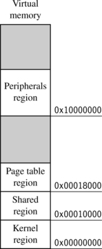
The privileged kernel region stores the system software; it contains the operating system kernel code and data. The region uses fixed addressing to avoid the complexity of remapping when changing to a system mode context. It also contains the vector table and the stacks for handling FIQ, IRQ, SWI, UND, and ABT exceptions.
The shared memory region is located at a fixed address in virtual memory. All tasks use this region to access shared system resources. The shared memory region contains shared libraries and the transition routines for switching from privileged mode to user mode during a context switch.
The page table region contains five page tables. Although the page table region is 32 KB in size, the system uses only 20 KB: 16 KB for the master table and 1 KB each for the four L2 tables.
The peripheral region controls the system device I/O space. The primary purpose of this region is to establish this area as a noncached, nonbuffered region. You don’t want to have input, output, or control registers subject to the stale data issues of caching or the time sequence delays involved in using the write buffer.
This region also prevents user mode access to peripheral devices; thus, access to the devices must be made through device drivers. This region permits privileged access only; no user access is allowed. In the demonstration, this is a single region, but in a more refined system, there would be more regions defined to provide finer control over individual devices.
14.10.2 STEP 2: DEFINE VIRTUAL MEMORY MAPS FOR EACH TASK
There are three user tasks that run during three time slice intervals. Each task has an identical virtual memory map.
Each task sees two regions in its memory map: a dedicated 32 KB task region at 0×400000, and a 32 KB shared memory region at 0×8000 (see Figure 14.18).
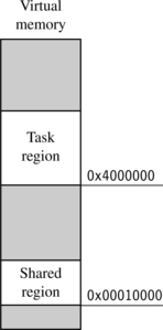
The task region contains the text, data, and stack of the running user task. When the scheduler transfers control from one task to another, it must remap the task region by changing the L1 page table entry to point to the upcoming task’s L2 page table. After the entry is made, the task region points to the physical location of the next running task.
The shared region is a fixed system software region. Its function is described in Section 14.10.1.
14.10.3 STEP 3: LOCATE REGIONS IN PHYSICAL MEMORY
The regions we defined for the demonstration must be located in physical memory at addresses that do not overlap or conflict. Table 14.10 shows where we located all the regions in physical memory as well as their virtual addresses and size. The table also lists our choice of page size for each region and the number of pages that need to be translated to support the size of each region.
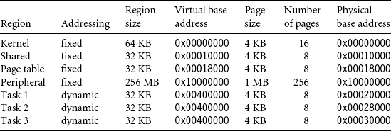
Table 14.10 lists the four regions that use fixed page tables during system operation: the kernel, shared memory, page table, and peripheral regions.
The task region dynamically changes page tables during system operation. The task region translates the same virtual address to a different physical address that depends on the running task.
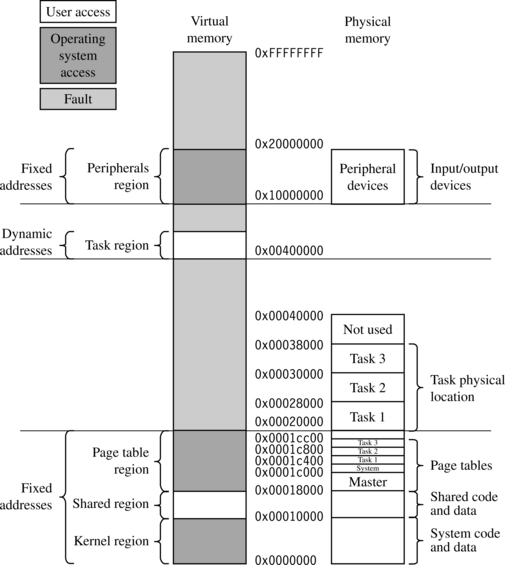
Figure 14.19 shows the placement of the regions in virtual and physical memory graphically. The kernel, shared and page table regions map directly to physical memory as blocks of sequential page frames. Above this area are the page frames dedicated to the three user tasks. The tasks in physical memory are 32 KB fixed partitions, also sequential page frames. Sparsely scattered over 256 MB of physical memory are the memory-mapped peripheral I/O devices.
14.10.4 STEP 4: DEFINE AND LOCATE THE PAGE TABLES
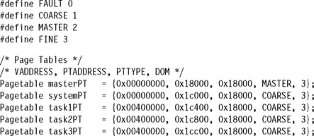
We previously dedicated a region to hold the page tables in the system. The next step is to locate the actual page table within the region to physical memory. Figure 14.20 shows a close-up detail of where the page table region maps to physical memory. It is a blow-up of the page tables shown in Figure 14.19. We spread the memory out a little to show the relationship between the L1 master page table and the four L2 page tables. We also show where the translation data is located in the page tables.
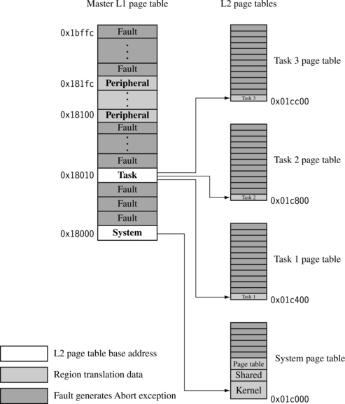
The one master L1 page table locates the L2 tables and translates the 1 MB sections of the peripheral region. The system L2 page table contains translation address data for three system regions: the kernel region, shared memory region, and page table region. There are three task L2 page tables that map to the physical addresses of the three concurrent tasks.
Only three of the five page tables are active simultaneously during run time: the L1 master table, the L2 system table, and one of the three L2 task page tables.
The scheduler controls which task is active and which tasks are dormant by remapping the task region during a context switch. Specifically, the master L1 page table entry at address 0x18010 is changed during the context switch to point to the L2 page table base address of the next active task.
14.10.5 STEP 5: DEFINE PAGE TABLE AND REGION DATA STRUCTURES
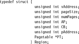
For the example, we define two data structures used to configure and control the system. These two data structures represent the actual code used to define and initialize the page tables and regions discussed in previous sections. We define two data types, a Pagetable type that contains the page table data, and a Region type that defines and controls each region in the system.
The type definition for the Pagetable structure, with a description of the members in the Pagetable structure, is:
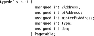
![]() vAddress identifies the starting address of a 1 MB section of virtual memory controlled by either a section entry or an L2 page table.
vAddress identifies the starting address of a 1 MB section of virtual memory controlled by either a section entry or an L2 page table.
![]() ptAddress is the address where the page table is located in virtual memory.
ptAddress is the address where the page table is located in virtual memory.
![]() masterPtAddress is the address of the parent master L1 page table. If the table is an L1 table, then the value is the same as ptAddress.
masterPtAddress is the address of the parent master L1 page table. If the table is an L1 table, then the value is the same as ptAddress.
![]() type identifies the type of the page table, it can be COARSE, FINE, or MASTER.
type identifies the type of the page table, it can be COARSE, FINE, or MASTER.
![]() dom sets the domain assigned to the 1 MB memory blocks of an L1 table entry.
dom sets the domain assigned to the 1 MB memory blocks of an L1 table entry.
We use the Pagetable type to define the five page tables used in the system. Together the Pagetable structures form a block of page table data that we use to manage, fill, locate, identify, and set the domain for all active and nonactive page tables. We refer to this block of Pagetables as the page table control block (PTCB) for the remainder of this demonstration.
The five Pagetables described in previous sections and shown in Figure 14.20 with their initialization values, are
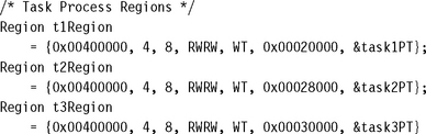
The type definition for the Region structure, with a description of the members in the Region structure, is
![]() vAddress is the starting address of the region in virtual memory.
vAddress is the starting address of the region in virtual memory.
![]() pageSize is the size of a virtual page.
pageSize is the size of a virtual page.
![]() numPages is the number of pages in the region.
numPages is the number of pages in the region.
![]() AP is the region access permissions.
AP is the region access permissions.
![]() CB is the cache and write buffer attributes for the region.
CB is the cache and write buffer attributes for the region.
![]() pAddress is the starting address of the region in virtual memory.
pAddress is the starting address of the region in virtual memory.
![]() *PT is a pointer to the Pagetable in which the region resides.
*PT is a pointer to the Pagetable in which the region resides.
All of the Region data structures together form a second block of data that we use to define the size, location, access permission, cache and write buffer operation, and page table location for the regions used in the system. We refer to this block of regions as the region control block (RCB) for the remainder of this demonstration.
There are the seven Region structures that define the regions described in previous sections and shown in Figure 14.19. Here are the initialization values for each of the four system software and three task Regions in the RCB:
14.10.6 STEP 6: INITIALIZE THE MMU, CACHES, AND WRITE BUFFER
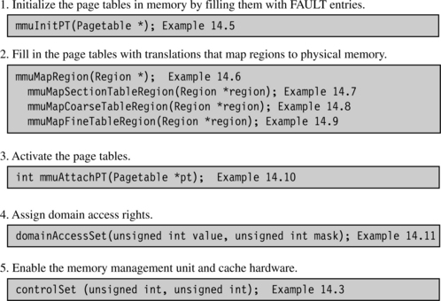
Before the MMU and the caches and write buffer are activated, they must be initialized. The PTCB and RCB hold the configuration data for the three components. There are five parts to initialize the MMU:
1. Initialize the page tables in main memory by filling them with FAULT entries.
2. Fill in the page tables with translations that map regions to physical memory.
The first four parts configure the system and the last part enables it. In the following sections we provide routines to perform the five parts to the initialization process; the routines are listed by function and example number in Figure 14.21.
14.10.6.1 Initializing the Page Tables in Memory
The first part in initializing the MMU is to set the page tables to a known state. The easiest way to do this is to fill the page tables with FAULT page table entries. Using a FAULT entry makes sure that no valid translations exist outside those defined by the PTCB. By setting all the page table entries in all the active page tables to a FAULT, the system will generate an abort exception for an entry not later filled in using the PTCB.
EXAMPLE 14.5
The routine mmuInitPT initializes a page table by taking the memory area allocated for a page table and setting it with FAULT values. It is called using the following function prototype:
![]()
The routine takes a single argument, which is a pointer to a Pagetable in the PTCB.
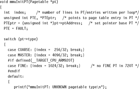
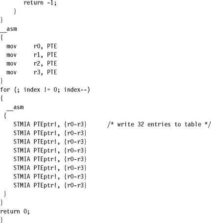
mmuInitPT starts with the base page table address PTEptr and fills the page table with FAULT entries. The size of the table is determined by reading the type of Pagetable defined in pt->type. The table type can be the master L1 page table with 4096 entries, a coarse L2 page table with 256 entries, or a fine L2 page table with 1024 entries.
The routine fills the table by writing small blocks to memory using a loop. The routine determines the number of blocks to write index from the number of entries in the page table divided by the number of entries written per loop. A switch statement selects the Pagetable type and branches to the case that sets the index size for the table. The procedure completes by executing the loop that fills the table. Note the __asm keyword to invoke the inline assembler; this reduces the execution time of the loop by using the stmia store multiple instruction.
14.10.6.2 Filling Page Tables with Translations
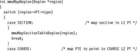
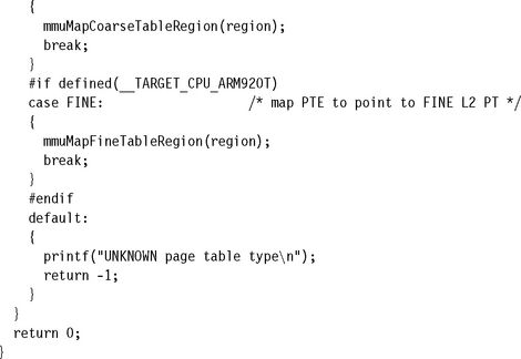
The second part in initializing the MMU is to convert the data held in the RCB into page table entries and to copy them into the page tables. We provide several routines to convert the data in the RCB to entries in a page table. The first high-level routine mmuMapRegion determines the type of page table and then calls one of three routines to create the page table entries: mmuMapSectionTableRegion, mmuMapCoarseTableRegion, or mmuMapFineTableRegion.
To ease future porting of code, we advise not using tiny pages and the mmuMapFineTableRegion routine because the ARMv6 architecture doesn’t use the tiny page. The fine page table type has also been removed in the ARMv6 architecture because the need for it disappears without tiny pages.
Here is a description of the four routines:
![]() The mmuMapRegion routine determines the page table type and branches to one of the routines listed below; it is presented in Example 14.6.
The mmuMapRegion routine determines the page table type and branches to one of the routines listed below; it is presented in Example 14.6.
![]() mmuMapSectionTableRegion fills an L1 master table with section entries; it is presented in Example 14.7.
mmuMapSectionTableRegion fills an L1 master table with section entries; it is presented in Example 14.7.
![]() mmuMapCoarseTableRegion fills an L2 coarse page table with region entries; it is presented in Example 14.8.
mmuMapCoarseTableRegion fills an L2 coarse page table with region entries; it is presented in Example 14.8.
![]() mmuMapFineTableRegion fills an L2 fine page table with region entries; it is presented in Example 14.9.
mmuMapFineTableRegion fills an L2 fine page table with region entries; it is presented in Example 14.9.
Here is a list of the C function prototypes for the four routines:
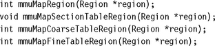
The four procedures all have a single input parameter, which is a pointer to a Region structure that contains the configuration data needed to generate page table entries.
EXAMPLE 14.6
Here is the high-level routine that selects the page table type:
Within the Region is a pointer to a Pagetable in which the region translation data resides. The routine determines the page table type region->PT->type and calls a routine that maps the Region into the page table in the format of the specified page table type.
There is a separate procedure for each of the three types of page table, section (L1 master), coarse, and fine (refer to Section 14.4).
EXAMPLE 14.7
Here is the first of the three routines that convert the region data to page table entries:
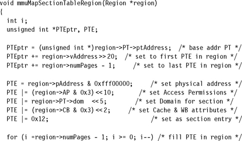
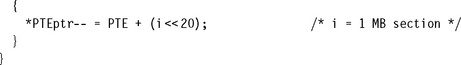
The mmuMapSectionTableRegion procedure begins by setting a local pointer variable PTEptr to the base address of the master L1 page table. It then uses the virtual starting address of the region to create an index into the page table where the region page table entries begin. This index is added to the variable PTEptr. The variable PTEptr now points to the start of the region entries in the page table. The next line calculates the size of the region and adds this value to PTEptr. The variable PTEptr now points to the last PTE for the region. The PTEptr variable is set to the end of the region so we can use a count-down counter in the loop that fills the page table with entries.
Next the routine constructs a section page table entry using the values in the Region structure; the entry is held in the local variable PTE. A series of ORs constructs this PTE from the starting physical address, the access permission, the domain, and cache and write buffer attributes. The format of the PTE is shown in Figure 14.6.
The PTE now contains a pointer to the first physical address of the region and its attributes. The counter variable i is used for two purposes: It is an offset into the page table, and it is added to the PTE variable to increment the physical address translation for the page frame. Remember, all regions in the demonstration map to sequential page frames in physical memory. The procedure concludes by writing all the PTEs for the region into the page table. It starts from the last translation entry and counts down to the first translation entry.
EXAMPLE 14.8
The next two routines, mmuMapCoarseTableRegion and mmuMapFineTableRegion, are very similar, which makes the descriptive text of the routines very similar; after reading the coarse page table example, you can skip the other example if you are not using tiny pages.
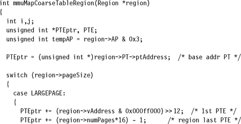
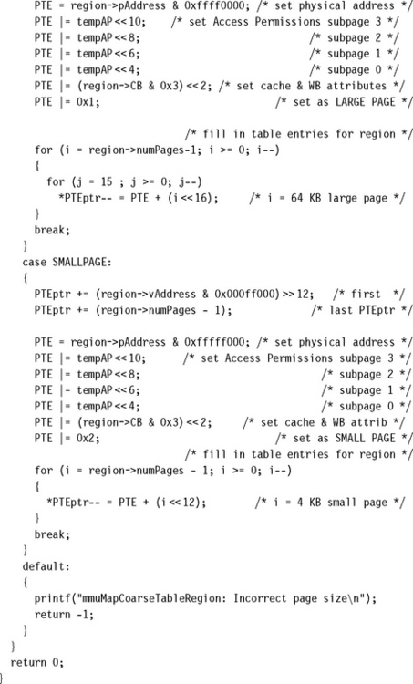
The routine begins by setting a local variable tempAP that holds the access permission for pages or subpages in the region. Next, it sets the variable PTEptr to point to the base address of the page table that will hold the mapped region.
The procedure then switches to handle either the case of a large or small page. The algorithms for the two cases are the same; only the format of the PTE and the way values are written into the page table are different.
At this point the variable PTEptr contains the starting address of the L2 page table. The routine then uses the starting address of the region region->vAddress to calculate an index to the first entry of the region in the page table. This index value is added to the PTEptr. The next line calculates the size of the region and adds this value to PTEptr. PTEptr now points to the last PTE for the region.
Next the routine constructs a page table entry variable PTE for either a large or a small entry from the values in the region passed into the routine. The routine uses a series of ORs to construct the PTE from the starting physical address, the access permission, and cache and write buffer attributes. See Figure 14.8 to review the formats of a large and small PTE.
The PTE now contains a pointer to the physical address of the first page frame for the region. The counter variable i is used for two purposes: First, it is an offset into the page table. Second it is added to the PTE variable to modify the address translation bit field to point to the next lower page frame in physical memory. The routine finishes by writing all the PTEs for the region into the page table. Note that there is a nested loop in the LARGEPAGE case: the j loop writes the required identical PTE to map a large page in a coarse page table (refer to Section 14.4 for details).
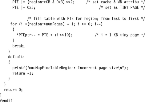
EXAMPLE 14.9
This example fills a fine page table with region translation information. Fine page tables are not available in the ARM720T and have been discontinued in the v6 architecture. For compatibility with these changes we would advise avoiding their use in new projects.

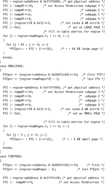
The routine begins by setting a local variable tempAP that holds the access permission for pages or subpages in the region. This routine does not support subpages with different access permissions. Next, the routine sets the variable PTEptr to point to the base of the page table that will hold the mapped fine-paged region.
The routine then switches to handle the three cases of a large, small, or tiny page. The algorithm for each of the three cases is the same; only the format of the PTE and the way values are written into the page table differ.
At this point the variable PTEptr contains the starting address of the L2 page table. The routine then takes the starting address of the region region->vAddress and calculates an index to the first region entry in the page table. This index value is added to the PTEptr. The next line determines the size of the region and adds this value to PTEptr. PTEptr now points to the last PTE for the region.
Next the routine constructs the PTE for a either a large, small, or tiny entry from the values in the region. A series of ORs constructs the PTE from the starting physical address, the access permission, and cache and write buffer attributes. Figure 14.8 shows the formats for large, small, and tiny page table entries.
The PTE now contains a pointer to the physical address of the first page frame and attributes for the region. A counter variable i is used for two purposes: It is an offset into the page table, and it is added to the PTE variable to change the address translation so it points to the next lower page frame in physical memory. The procedure concludes by looping until all the PTEs for the region are mapped in the page table. Note the nested loop in the LARGEPAGE and SMALLPAGE cases: the j loop writes the required identical PTE to properly map the given page in a fine page table.
14.10.6.3 Activating a Page Table
A page table can reside in memory and not be used by the MMU hardware. This happens when a task is dormant and its page tables are mapped out of active virtual memory. However, the task remains resident in physical memory, so it is immediately available for use when a context switch occurs to activate it.
The third part in initializing the MMU is to activate the page tables needed to execute code located in the fixed regions.
EXAMPLE 14.10
The routine mmuAttachPT either activates an L1 master page table by placing its address into the TTB in the CP15:c2:c0 register, or activates an L2 page table by placing its base address into an L1 master page table entry.
It can be called using the following function prototype:
![]()
The procedure takes a single argument, a pointer to the Pagetable to activate and add new translations from virtual to physical virtual memory.
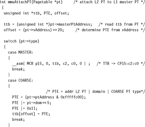
The first thing the routine does is prepare two variables, the base address of the master L1 page table, ttb, and an offset into the L1 page table, offset. The offset variable is created from the virtual address of the page table. To calculate the offset, it takes the virtual address and divides it by 1 MB by shifting the virtual address right by 20 bits. Adding this offset to the master L1 base address generates a pointer to the address within the L1 master table that represents the translation for the 1 MB section.
The procedure attaches the page table to the MMU hardware using the Pagetable type pt->type variable to switch to the case that attaches the page table. The three possible cases are described below.
The Master case attaches the master L1 page table. The routine attaches this special table using an assembly language MCR instruction to set the CP15:c2:c0 register.
The Coarse case attaches a coarse page table to the master L1 page table. This case takes the address of the L2 page table stored in the Pagetable structure and combines it with the Domain and the coarse table type, to build a PTE. The PTE is then written into the L1 page table using the previously calculated offset. The format of the coarse PTE is shown in Figure 14.6.
The Fine case attaches a fine L2 page table to the master L1 page table. This routine takes the address of the L2 page table stored in the Pagetable structure and combines it with the Domain and fine table type to build a PTE. The PTE is then written into the L1 page table using the previously calculated offset.
The previous sections presented the routines that condition, load, and activate the page tables while initializing the MMU. The last two parts set the domain access rights and enable the MMU.
14.10.6.4 Assigning Domain Access and Enabling the MMU
The fourth part in initializing the MMU is to configure the domain access for the system. The demonstration does not use the FCSE, nor does it need to quickly expose and hide large blocks of memory, which eliminates the need to use the S and R access control bits in the CP:c1:c0 register. This means that the access permissions defined in the page tables are enough to protect the system, and there is reason to use Domains.
However, the hardware requires all active memory areas to have a domain assignment and be granted domain access privileges. The minimum domain configuration places all regions in the same domain and sets the domain access to client access. This domain configuration makes the access permission entries in the page tables the only permission system active.
In this demo, all regions are assigned Domain 3 and have client domain access. The other domains are unused and masked by the fault entry in the unused page table entries of the L1 master page table. Domains are assigned in the master L1 page table, and domain access is defined in the CP15:c3:c0 register.
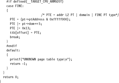
EXAMPLE 14.11
domainAccessSet is a routine that sets the access rights for the 16 domains in the domain access control register CP15:c3:c0:0. It can be called from C using the following function prototype:
![]()
The first argument passed to the procedure is an unsigned integer containing bit fields that set the Domain access for the 16 domains. The second parameter defines which domains need their access rights changed. The routine first reads the CP15:r3 register and places it in the variable c3format. The routine then uses the input mask value to clear the bits in c3format that need updating. The update is done by ORing c3format with value input parameter. The updated c3format is finally written back out to the CP15:c3 register to set the domain access.
Enabling the MMU is the fifth and final last part in the MMU initialization process. The routine controlSet, shown as Example 14.3, enables the MMU. It is advisable to call the controlSet procedure from a “fixed” address area.
14.10.6.5 Putting It All Together: Initializing the MMU for the Demonstration.
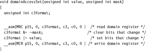
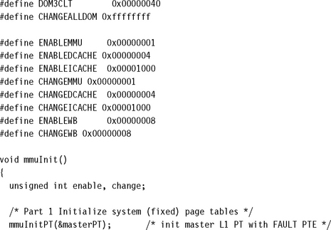
The routine mmuInit calls the routines described in previous sections to initialize the MMU for the demonstration. While reading this section of code it will be helpful to review the control blocks shown in Section 14.10.5.
The routine can be called using the following C function prototype:
![]()
EXAMPLE 14.12
This example calls the routines previously described as the five parts in the process of initializing the MMU. The five parts are labeled as comments in the example code.
The mmuInit begins by initializing the page tables and mapping regions in the privileged system area. The first part initalizes the fixed system area with calls to the routine mmuInitPT. These calls fill the L1 master and the L2 page tables with FAULT values. The routine calls mmuInitPT five times: once to initialize the L1 master page table, once to initialize the system L2 page table, and then calls mmuInitPT three more time to initialize the three task page tables:
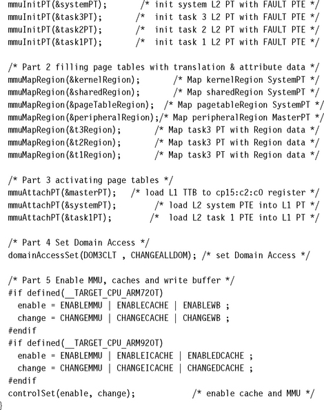
The second part then maps the seven Regions in the system into their page tables by calling mmuMapRegion seven times: four times to map the kernel, shared, page table, and peripheral regions, and three times to map the three task regions. mmuMapRegion converts the data from the control blocks into page table entries that are then written to a page table.
The third part in initalizing the MMU is to activate the page tables necessary to start the system. This is done by calling mmuAttachPT three times. First, it activates the master L1 page table by loading its base address into the TTB entry in CP15:c2:c0. The routine then activates the L2 system page table. The peripheral region is comprised of 1 MB pages residing in the L1 master page table and is activated when the master L1 table is actived. The third part is completed by activating the first task that runs after the system is enabled with a call to mmuAttachPT. In the demo, the first task to run is Task 1.
The fourth part in initializing the MMU is to set domain access by calling domainAccessSet. All regions are assigned to Domain 3 and the domain access for Domain 3 set to client access.
The mmuInit completes part five by calling controlSet to enable the MMU and caches.
When the routine mmuInit completes, the MMU is initialized and enabled. The final task in setting up the multitasking demonstration system is to define the procedural steps needed to perform a context switch between two tasks.
14.10.7 STEP 7: ESTABLISH A CONTEXT SWITCH PROCEDURE
A context switch in the demonstration system is relatively simple. There are six parts to performing a context switch:
1. Save the active task context and place the task in a dormant state.
2. Flush the caches; possibly clean the D-cache if using a writeback policy.
3. Flush the TLB to remove translations for the retiring task.
4. Configure the MMU to use new page tables translating the common virtual memory execution area to the awakening task’s location in physical memory.
The routines to perform all the parts just listed have been presented in previous sections. We list the procedure here. Parts 1, 5, and 6 were provided in Chapter 11; refer to that chapter for more details. Parts 2, 3, and 4 are the additions needed to support a context switch using an MMU and are shown here with the arguments needed to switch from task 1 to task 2 in the demonstration.
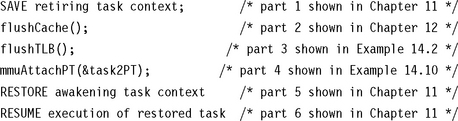
14.11 THE DEMONSTRATION AS MMUSLOS
Many of the concepts and the examples from the MMU demonstration code have been incorporated into a functional control system we call mmuSLOS. It is an extension of the control system called SLOS presented in Chapter 11.
mpuSLOS is the memory protection unit extension to SLOS, and was described in Chapter 13. We use the mpuSLOS variant as the base source code for mmuSLOS. All three variants can be found on the publisher’s Web site. We changed three major parts of the mpuSLOS code:
![]() The MMU tables are created during the mmuSLOS initialization stage.
The MMU tables are created during the mmuSLOS initialization stage.
![]() The application tasks are built to execute at 0x400000, but are loaded at a different physical addresses. Each application task executes in a virtual memory starting at the execution address. The top of the stack is located as an 32 KB offset from the execution address.
The application tasks are built to execute at 0x400000, but are loaded at a different physical addresses. Each application task executes in a virtual memory starting at the execution address. The top of the stack is located as an 32 KB offset from the execution address.
![]() Each time the scheduler is called, the active 32 KB page in the MMU table is changed to reflect the new active application/task.
Each time the scheduler is called, the active 32 KB page in the MMU table is changed to reflect the new active application/task.
14.12 SUMMARY
The chapter presented the basics of memory management and virtual memory systems. A key service of an MMU is the ability to manage tasks as independent programs running in their own private virtual memory space.
An important feature of a virtual memory system is address relocation. Address relocation is the translation of the address issued by the processor core to a different address in main memory. The translation is done by the MMU hardware.
In a virtual memory system, virtual memory is commonly divided into parts as fixed areas and dynamic areas. In fixed areas the translation data mapped in a page table does not change during normal operation; in dynamic areas the memory mapping between virtual and physical memory frequently changes.
Page tables contain descriptions of virtual page information. A page table entry (PTE) translates a page in virtual memory to a page frame in physical memory. Page table entries are organized by virtual address and contain the translation data to map a page to a page frame.
The functions of an ARM MMU are to:
![]() read level 1 and level 2 page tables and load them into the TLB
read level 1 and level 2 page tables and load them into the TLB
![]() store recent virtual-to-physical memory address translations in the TLB
store recent virtual-to-physical memory address translations in the TLB
![]() perform virtual-to-physical address translation
perform virtual-to-physical address translation
![]() enforce access permission and configure the cache and write buffer
enforce access permission and configure the cache and write buffer
An additional special feature in an ARM MMU is the Fast Context Switch Extension. The Fast Context Switch Extension improves performance in a multitasking environment because it does not require flushing the caches or TLB during a context switch.
A working example of a small virtual memory system provided in-depth details to set up the MMU to support multitasking. The steps in setting up the demonstration are to define the regions used in the fixed system software of virtual memory, define the virtual memory maps for each task, locate the fixed and task regions into the physical memory map, define and locate the page tables within the page table region, define the data structures needed to create and manage the regions and page tables, initialize the MMU by using the defined region data to create page table entries and write them to the page tables, and establish a context switch procedure to transition from one task to the next.