
Motor Control Projects
Abstract
Brushed DC (BDC) motors are low-cost, easy-to-drive electric motors that are used in many movement-based applications. These motors have two terminals and the voltage is applied across these terminals. The speed of the motor is directly proportional to the amount of the applied voltage. The direction of rotation can be changed easily by changing the polarity of the voltage across the terminals. The torque produced by the motor shaft is directly proportional to the current flowing through the motor windings. Stepper motors are used in applications where it is required to control the motor shaft position accurately. In this chapter projects are given to show how Mbed-based programs can be developed to control BDC motors and stepper motors.
Keywords
Motor control; Brushed motor; MOSFET; Servo motor; Stepper motor; Unipolar motor; Bipolar motor
9.1 Overview
In this chapter we shall be developing projects using electric motors with the Nucleo-F411RE development board. The projects will cover the following types of electric motors: brushed DC (BDC) motors, servo motors, and stepper motors.
9.2 Project 1—Simple Brushed DC Motor Control
9.2.1 Description
In this project a small BDC motor operating with 3–12 V is connected to one of the output ports of the nucleo-F411RE development board. The motor is turned ON for 10 s, then stopped for 5 s, and turned ON again for 10 s. This process is repeated continuously until stopped by the user. The motor speed is fixed in this project.
9.2.2 Aim
The aim of this project is to show how a small BDC motor can be connected and controlled from the Nucleo-F411RE development board.
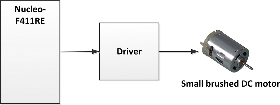
9.2.3 Block Diagram
The BDC motors are low-cost, easy-to-drive electric motors that are used in many movement-based applications. These motors have two terminals and the voltage is applied across these terminals. The speed of the motor is directly proportional to the amount of the applied voltage. The direction of rotation can be changed easily by changing the polarity of the voltage across the terminals. The torque produced by the motor shaft is directly proportional to the current flowing through the motor windings. Fig. 9.1 shows the block diagram of the project. A driver circuit is used to power the motor as the current required by the motor is beyond the maximum capacity of a GPIO (general-purpose input/output) port.
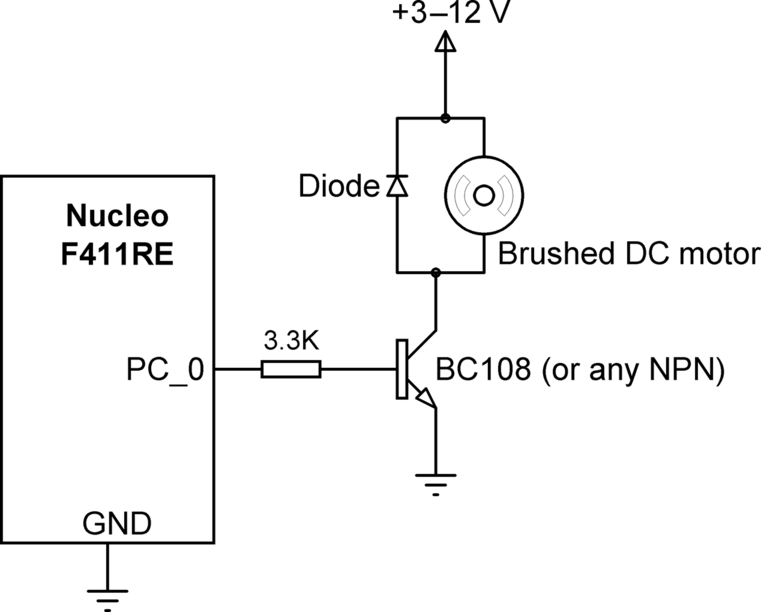
9.2.4 Circuit Diagram
Fig. 9.2 shows the circuit diagram. The GPIO port PC_0 is connected to the motor through a switching transistor and a base resistor. The motor starts rotating when logic 1 is applied to the base of the transistor. Although a BC108-type transistor is used in this design, in general any NPN (negative-positive-negative)-type transistor can be used as long as the maximum current required by the motor is below the maximum allowable collector current of the transistor. Notice that a diode is connected across the motor terminals to protect the transistor from back emf generated by the motor windings.
9.2.5 The PDL
The algorithm of this project is very simple. Fig. 9.3 shows the operation of the program as a PDL.
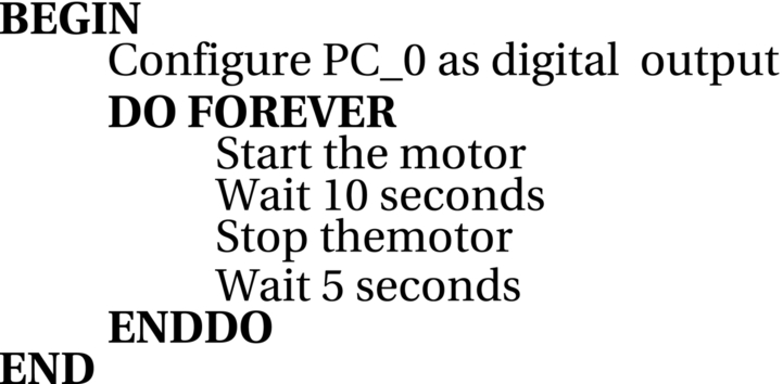
9.2.6 Program Listing
The program listing (program: SimpleMotor) is shown in Fig. 9.4. At the beginning of the program GPIO port PC_0 is defined as an output and is assigned to variable Motor, ON and OFF are defined as 1 and 0, respectively. The program runs in an endless loop formed using a while statement. Inside this loop the motor is activated for 10 s, then stopped for 5 s, and then again activated for 10 s. This process continues until stopped manually by the user.

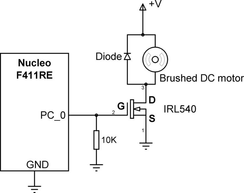
9.2.7 Using a Metal-Oxide-Semiconductor Field-Effect Transistor (MOSFET)
A MOSFET transistor can be used for motors requiring larger currents instead of a bipolar transistor. Fig. 9.5 shows the circuit diagram with an IRL540-type MOSFET transistor. This MOSFET has logic level gate drive and is therefore compatible with microcontroller output circuits. It is also possible to use a relay instead of transistor for even larger voltages and currents. This is shown in Fig. 9.6.

9.2.8 Suggestions for Additional Work
In this project the motor speed is the same when the motor is activated. Modify the program given in Fig. 9.4 by sending PWM waveform to the motor and change the speed of the motor by changing the Duty Cycle of this waveform. Try setting the Duty Cycle to 25%, 50%, and 100%.
9.3 Project 2—Changing the Motor Rotation Direction
9.3.1 Description
In this project the User button on the Nucleo-F411RE development board is used such that when the button is pressed the motor rotates in one direction, and when the button is released the motor rotates in the opposite direction. The motor speed is fixed in this project.
9.3.2 Aim
The aim of this project is to show how the rotation direction of the motor can easily be changed.
9.3.3 Block Diagram
The block diagram of the project is shown in Fig. 9.7. A direction control circuit (also known as H-bridge) is used to change the rotation direction of the motor when the button is pressed.

9.3.4 Circuit Diagram
Fig. 9.8 shows the circuit diagram of the project. In this project four MOSFET transistors are used to control the rotation direction of the motor. It is also possible to design this circuit using bipolar transistors. This circuit is also called the H-Bridge. The operation of the circuit is as follows:

The A, B, C, D terminals of the H-Bridge are connected to GPIO port pins PC_0, PC_1, PC_2, and PC_3 of the development board, respectively.
9.3.5 The PDL
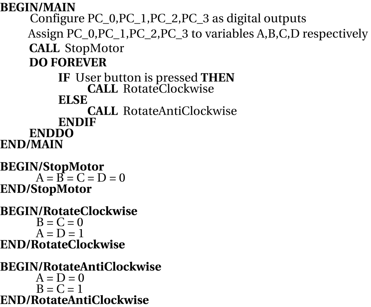
The algorithm of this project is very simple. Fig. 9.9 shows the operation of the program as a PDL.
9.3.6 Program Listing
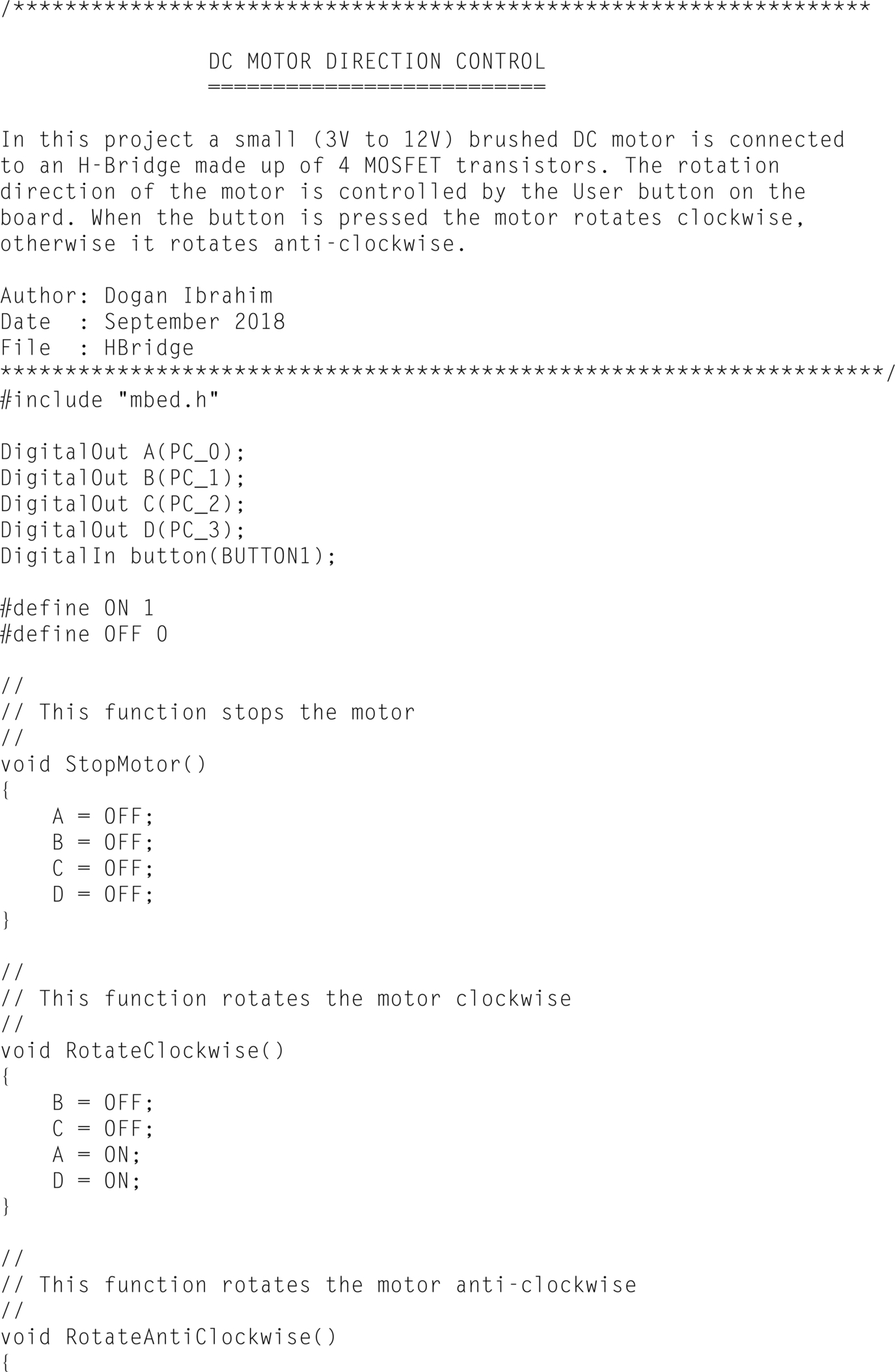
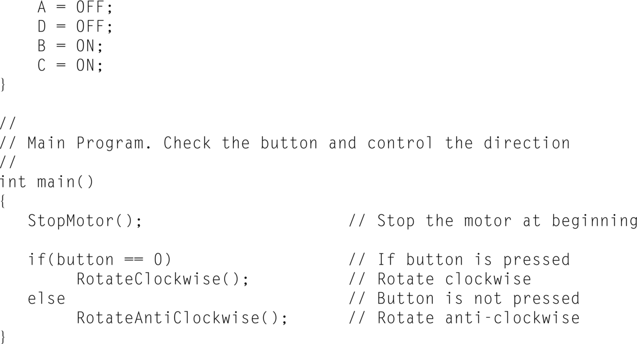
The program listing (program: HBridge) is shown in Fig. 9.10. At the beginning of the program, A, B, C, D terminals of the H-Bridge are configured as outputs and User button is configured as input. Three functions are developed: StopMotor, RotateClockwise, and RotateAntiClockwise. At the beginning of the program the motor is stopped. Inside the main program the state of the User button is checked and if the button is pressed then the motor is rotated clockwise, otherwise it is rotated anticlockwise.
9.3.7 Suggestions for Additional Work
In this project the motor speed is the same when the motor is activated. Modify the program given in Fig. 9.10 by sending PWM waveform to the motor and change the speed of the motor by changing the Duty Cycle of this waveform. Try setting the Duty Cycle to 25%, 50%, and 100%.
9.4 Project 3—Simple Servo Motor Control
9.4.1 Description
In this project a small servo motor is connected to one of the GPIO ports of the Nucleo-F411RE development board. The servo motor is controlled as follows:
- • position the servo moor all the way to the right (0 degrees)
- • wait for 3 s
- • position the servo motor all the way to the left (180 degrees)
- • wait for 3 s
- • position the servo motor in the middle (90 degrees)
9.4.2 Aim
The aim of this project is to show how a servo motor can be controlled.
9.4.3 Block Diagram
Servo motors are DC motors with built-in feedback circuits so that the positions of their shaft can be controlled accurately. These motors have three terminals: power, ground, and control. The control terminal is driven with PWM waveform usually with a period of 20 ms (50 Hz). In this project the small SG90 servo motor is used. Fig. 9.11 shows the shaft positions of this motor. When the PWM pulse duration is 1.5 ms then the shaft is in the middle position. This is also known as the 90 degrees position. When the PWM pulse duration is 2 ms then the shaft is all the way to the left, or 180 degrees. When the PWM pulse duration is 1 ms then the shaft is all the way to the right, or 0 degrees.

The SG90 has the following pin configuration:
The block diagram of the project is shown in Fig. 9.12. The SG90 servo motor has the following characteristics:
- • Operating voltage: 3.3–6 V
- • Running current: 220 ± 50 mA
- • Weight: 9 g
- • Speed: 01 s/60 degrees

9.4.4 Circuit Diagram
Fig. 9.13 shows the circuit diagram of the project. Notice that the servo motor is driven from the + 5 V pin of the Nucle-F411RE development board (Pin 18, connector CN7). This pin has enough current capacity to drive the SG90 servo motor. In this project the servo motor control pin is connected to GPIO pin PA_8 which is a PWM channel pin.

9.4.5 The PDL
The algorithm of this project is very simple. Fig. 9.14 shows the operation of the program as a PDL.

9.4.6 Program Listing
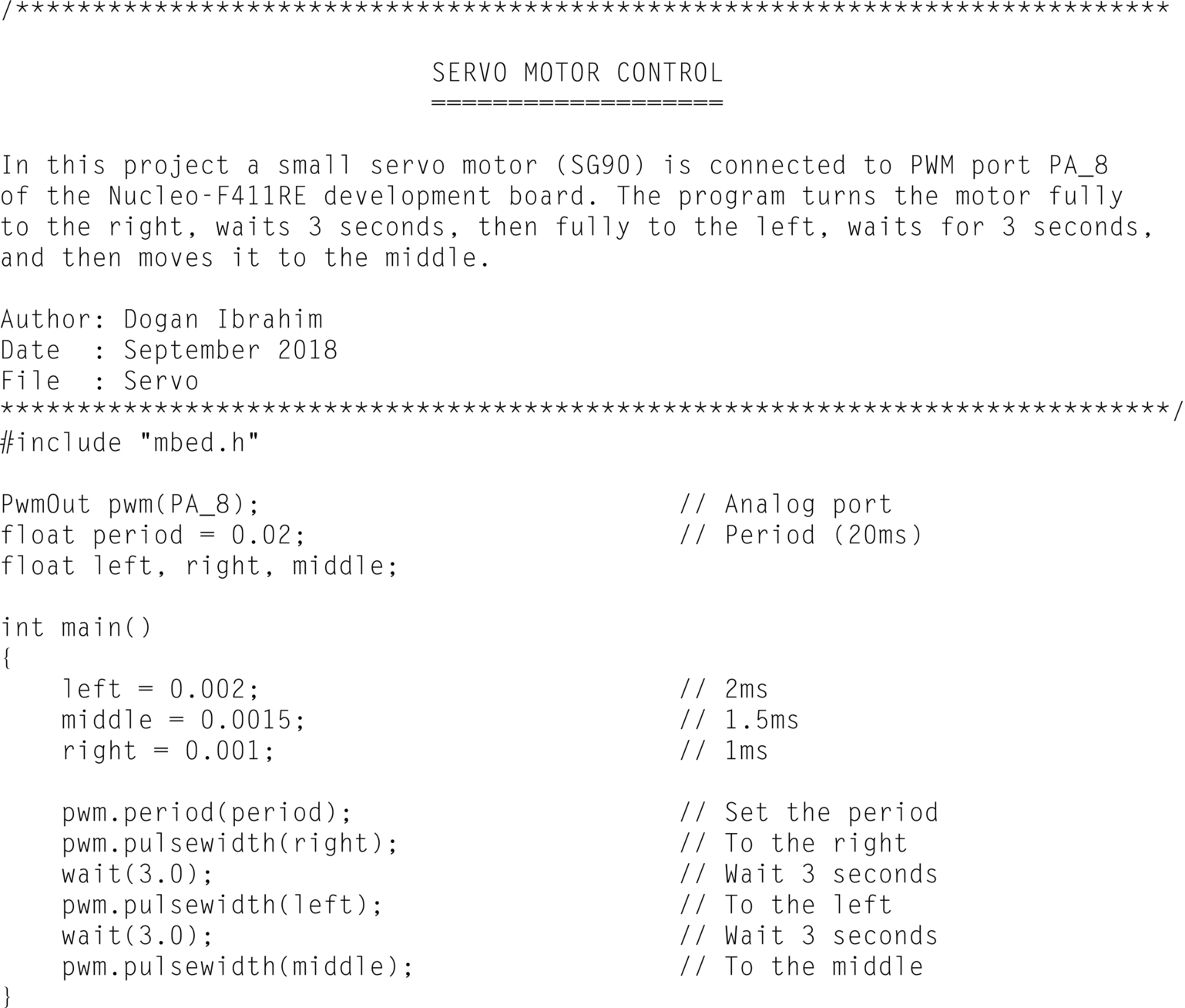
The program listing (program: Servo) is shown in Fig. 9.15. At the beginning of the program variable pwm is assigned to PWM port PA_8. Inside the main program the period of the PWM waveform is set to 20 ms. The servo motor shaft is then turned fully right by setting the pulse width to 1 ms. After 3 s of delay the pulse width is set to 2 ms which then turns the motor shaft fully left. Finally, the motor shaft is moved to the middle position.
9.4.7 Suggestions for Additional Work
Modify this project by connecting a potentiometer to one of the analog input ports of the development board. Then, write a program to turn the servo motor shaft as the potentiometer arm is rotated left and right.
9.5 Project 4—Simple Stepper Motor Control
9.5.1 Description
In this project a small stepper motor is connected to the Nucleo-F411RE development board through a driver module. The motor shaft is rotated as follows:
- • three complete revolutions in one direction
- • stop for 3 s
- • three complete revolutions in the reverse direction
9.5.2 Aim
The aim of this project is to show how a stepper motor can be controlled.
9.5.3 Block Diagram
Stepper motors rotate by small steps in response to applied voltage pulses. The motors have several windings and the voltage steps must be applied in the correct sequences to turn the motor shaft. Basically, there are two types of stepper motors: unipolar and bipolar.
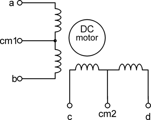
Unipolar Stepper Motors
As shown in Fig. 9.16, these motors have four windings and five or six leads depending on the whether or not the common leads are joined together. Unipolar motors can be operated in full-step or half-step modes. Half-step mode requires more steps for rotation but provides higher precision. Full-step modes can be either one phase or two phase. In one-phase mode only one winding is excited at any time, while in two-phase mode two windings are excited at the same time. Two-phase mode gives higher torque. Table 9.1 illustrates the two-phase full-step mode of operation which is the mode used in this project.

Bipolar Stepper Motors
Bipolar stepper motors have two windings as shown in Fig. 9.17. The drive sequence of these motors is presented in Table 9.2.


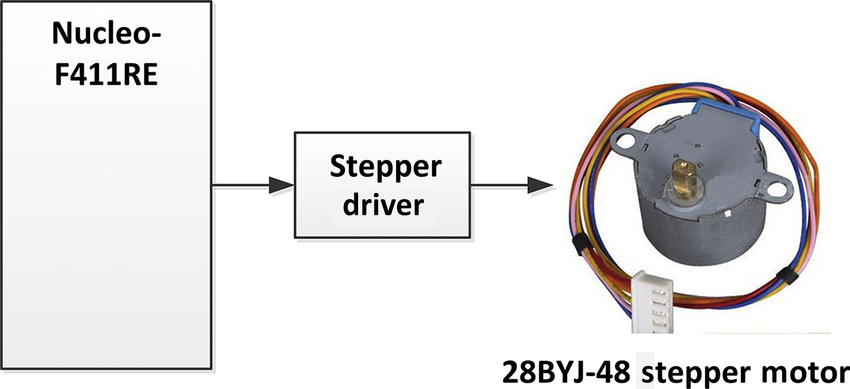
The block diagram of this project is shown in Fig. 9.18. A small 28BYJ-48-type unipolar geared stepper motor is used in this project. This motor has the following features:
- • Operating voltage: 5 V
- • Number of phases: 4
- • Gear ratio: 64
The common pins of the windings are joined together and as a result the motor has only five terminals. The terminals are identified as follows:
9.5.4 Circuit Diagram
In this project a ULN2003-type stepper motor driver module is used. This module (see Fig. 9.19) has four inputs IN1, IN2, IN3, and IN4. Additionally four LEDs are provided named as A, B, C, and D. The LEDs indicate the state of the four inputs. These LEDs can be enabled or disabled by a short jumper provided at the bottom part of the module. External power (+ 5 to + 12 V) for the motor is applied through the connectors provided at the bottom part of the module (next to the LED enable/disable jumper). The motor is connected to the four connectors located at the top part of the module next to the LEDs.

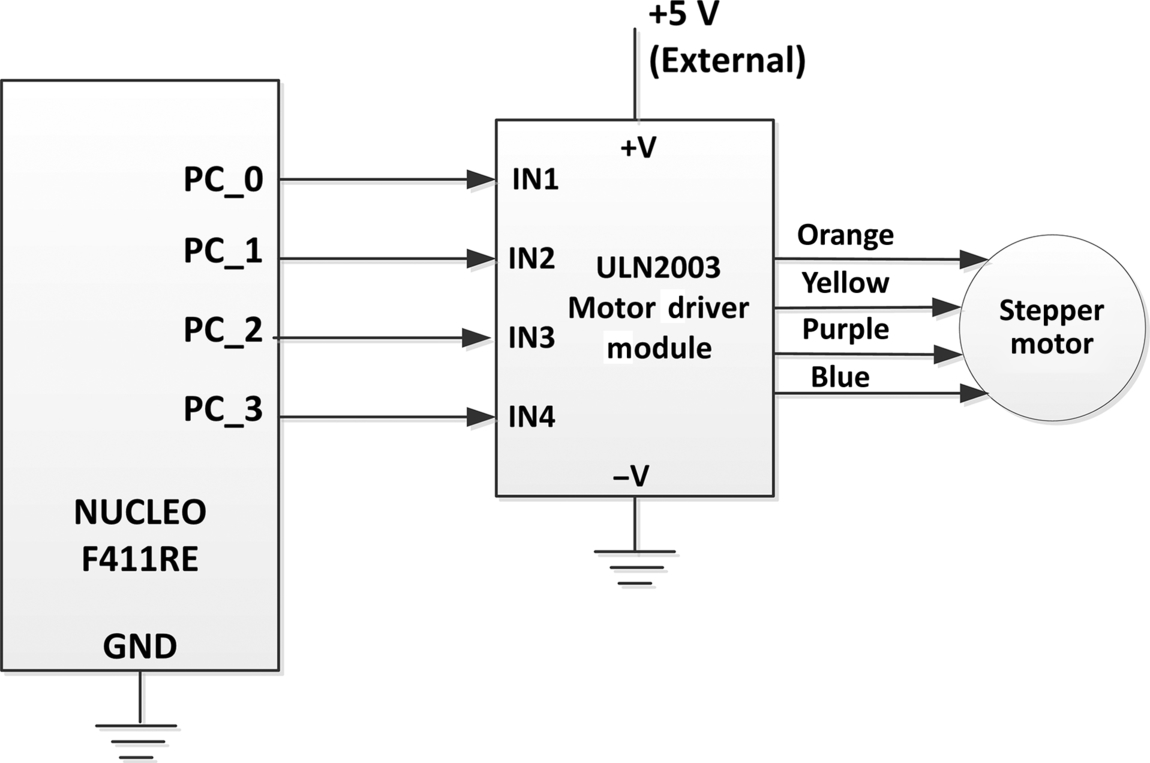
The circuit diagram of the project is shown in Fig. 9.20. GPOI pins PC_0, PC_1, PC_2, and PC_3 of the Nucleo-F411RE development board are connected to pins IN1, IN2, IN3, and IN4 of the ULN2003 module, respectively. A 5 V supply is applied from the development board pin 18 of connector CN7. The stepper motor is connected to the ULN2003 module as shown in the figure.
9.5.5 The PDL
The PDL of the program is shown in Fig. 9.21.
9.5.6 Program Listing
In this project the stepper moor is operated in two-phase full-step mode. The 28BYJ-48 stepper motor has four steps per cycle and 11.25 degrees/step (4 × 11.25 = 45 degrees/cycle). This corresponds to 360/11.25 = 32 steps for one complete revolution of the internal motor shaft. The motor is geared with a gear ratio of 64 (it is exactly 63.68395), the number of steps for one complete revolution of the external motor shaft is 32 × 64 = 2048 steps/revolution, which corresponds to 2048/4 = 512 cycles with 4 steps/cycle. Therefore, we have to send 512 cycles × 4 pulses/cycle = 2048 steps to the motor for one complete revolution of its external shaft. Table 9.3 illustrates the step sequence for one cycle.
Table 9.3
| Step | 4 (Orange) IN1 | 3 (Yellow) IN2 | 2 (Pink) IN3 | 1 (Blue) IN4 |
|---|---|---|---|---|
| 1 | 1 | 1 | 0 | 0 |
| 2 | 0 | 1 | 1 | 0 |
| 3 | 0 | 0 | 1 | 1 |
| 4 | 1 | 0 | 0 | 1 |

The speed of a stepper motor depends on the delay inserted between each step. In full-step mode there are 2048 steps in a complete external revolution and therefore the speed of the motor in RPM (revolutions per minute) is given by
or
where RPM is the motor speed, and T is the delay between each step in milliseconds. The above equation can be written as
where T is in seconds. In this program we will choose the motor speed as 12 RPM, which gives the delay between each step as T = 0.0293/12 = 0.00244 s.
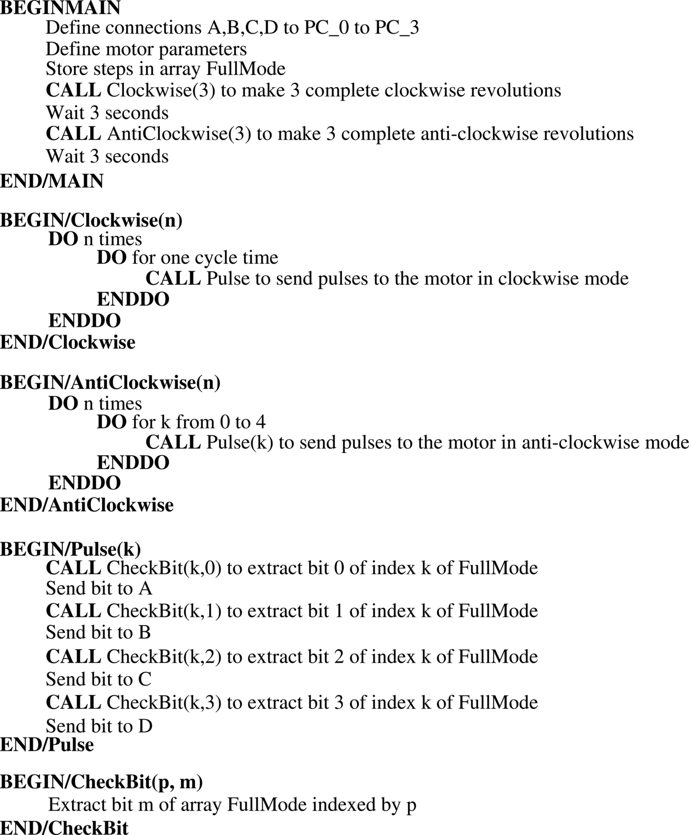
The program listing (program: Stepper) is shown in Fig. 9.22. At the beginning of the program the connection between the development board and the driver module are defined and various motor parameters such as the RPM, CyclesPerRev, and StepsPerCycle are defined. Notice that the speed of the motor is set to 12 RPM. The pulses to be sent in a cycle in full-step mode are stored in array FullMode. The program consists of a number of functions. Function Clockwise receives the argument RevCount and sends pulses to the motor to make complete RevCount clockwise rotations. Similarly, function AntiClockwise makes complete RevCount anticlockwise rotations. Function Pulse sends a cycle of pulses (four pulses) to the motor by calling function CheckBit which extracts the bits of array FullMode for a given step and sends the extracted bits to the motor windings. The main program calculates the delay between each step in seconds, calls function Clockwise with argument set to 3 to make three complete revolutions. After 3 s of delay function AntiClockwise is called with argument 3 so that three complete anticlockwise revolutions are made.


9.6 Summary
In this chapter we have learned about the following:
- • Types of electric motors
- • Controlling BDC motors
- • Controlling servo motors
- • Types of stepper motors
- • Controlling unipolar stepper motors
9.7 Exercises
- 1. Explain how the direction of rotation of a BDC motor can be changed.
- 2. Explain the differences between a BDC motor and a stepper motor.
- 3. Draw the circuit diagram to show how a bipolar stepper motor can be connected to a Nucleo-F411RE development board.
- 4. A unipolar stepper motor with a stepping angle of 10 degrees is connected to a Nucleo-F411RE development board. Write a program to rotate the motor by 90 degrees.
- 5. Explain the differences between a unipolar and a bipolar stepper motor.