
STM32 Nucleo Expansion Boards
Abstract
The STM32 Nucleo expansion boards plug on top of the Nucleo development boards and provide additional peripheral components and modules such as sensors, actuators, displays, and so on. These are professional quality boards that can be used during project development. The expansion boards are equipped with Arduino or Morpho compatible connectors so that they can be plugged on top of the Nucleo development boards. The combination of the STM32 Nucleo board and expansion boards is a scalable approach for application development, prototyping, or for product evaluation. This chapter gives the basic features of some of the commonly used expansion boards. Additionally, projects are given using some of the expansion boards with the Mbed integrated development environment and the Nucleo-F411Re development board.
Keywords
STM332 Nucleo expansion board; Using an STM32 Nucleo expansion board; STM32 Nucleo expansion board and Nucleo-F411RE; Mbed and STM32 Nucleo expansion board
17.1 Overview
The expansion boards plug on top of the Nucleo development boards and provide additional peripheral components and modules such as sensors, actuators, displays, and so on. These are professional quality boards that can be used during project development.
The expansion boards are equipped with Arduino or Morpho compatible connectors so that they can be plugged on top of the Nucleo development boards. The expansion boards are supported by STM32-based software modules (e.g., TrueSTUDIO, Keil MDK-ARM, System Workbench, STM32CubeMX) as well as by Mbed, thus making it very easy to develop complex projects in relatively short times. The combination of the STM32 Nucleo board and expansion boards is a scalable approach for application development, prototyping, or for product evaluation.
In this chapter we shall be looking at the features of some of the commonly used expansion boards and also develop some projects using some of the popular expansion boards. Further information on the expansion boards can be obtained from the following ST website:http://www.st.com/en/evaluation-tools/stm32-nucleo-expansion-boards.html?querycriteria=productId=SC1971
The pictures of the expansion boards in this chapter and the information contained in the chapter are a Copyright of STMicroelectronics and have been used here with their written permission: ©STMicroelectronics. Used with permission.
17.2 High-Power Stepper Motor Board (X-NUCLEO-IHM03A1)
This is a stepper motor driver expansion board (Fig. 17.1) designed for driving high-power bipolar stepper motors, and is based on powerSTEP01. The board is compatible with the Arduino UNO R3 connector. The basic features of this expansion board are as follows:
- • voltage range from 10.5 to 85 V
- • phase current up to 10 A rms
- • power OK and fault LEDs
- • up to 1/128 microstepping
- • programmable speed profile and overcurrent protection
- • sensorless stall detection
- • adjustable output slew rate
- • overtemperature protection

17.3 Two-Axis Stepper Motor Board (X-NUCLEO-IHM02A1)
This is a two-axis stepper motor driver expansion board (Fig. 17.2) based on two L6470 motor driver chips. The board is equipped with Arduino UNO R3 connectors. The board can drive one or two stepper motors through USART interface. The basic features of this expansion board are as follows:
- • 8–45 V operating voltage
- • 7 A peak (3 A rms) output current for each motor driver
- • USART communication with a PC
- • SPI interface that may be connected in a daisy chain configuration
- • five LEDs to indicate power, busy, and fault conditions

17.4 Low-Voltage Three-Phase Brushless DC Motor Board (X-NUCLEO-IHM11M1)
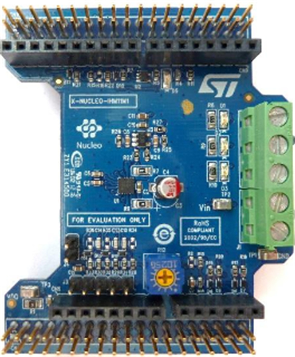
This is a low-voltage three-phase brushless DC motor driver expansion board (Fig. 17.3) based on the STSPIN230. The board is compatible with the Arduino UNO R3 connector. The board is designed for six-step and FOC algorithms. The basic features of this expansion board are as follows:
- • 1.8–10 V operation
- • up to 1.3 A rms current
- • overcurrent and short-circuit protection
- • thermal shutdown
- • current control with adjustable off time
- • hall/encoder sensor connector and circuit
- • potentiometer for speed regulation
17.5 Motion MEMS and Environmental Sensor Expansion Board (X-NUCLEO-IKS01A2)
This is a motion MEMS and environmental sensor expansion board (Fig. 17.4), equipped with three-dimensional (3D) accelerometer, 3D gyroscope, 3D magnetometer, humidity and temperature sensor, and ambient atmospheric pressure sensor. The board is interfaced via the I2C pin and is compatible with the Arduino UNO R3 connector. The basic features of this expansion board are as follows:
- • LSM6DSL MEMS 3D accelerometer (± 2/±4/±8/±16 g) and 3D gyroscope
- • LSM303AGR MEMS 3D accelerometer (± 2/±4/±8/±16 g) and MEMS 3D magnetometer (± 50 G)
- • LPS22HB MEMS pressure sensor (260–1260 hPa)
- • HTS221 capacitive relative humidity and temperature sensor
- • DIL24 socket for additional MEMS sensors (e.g., UV index)
- • I2C interface
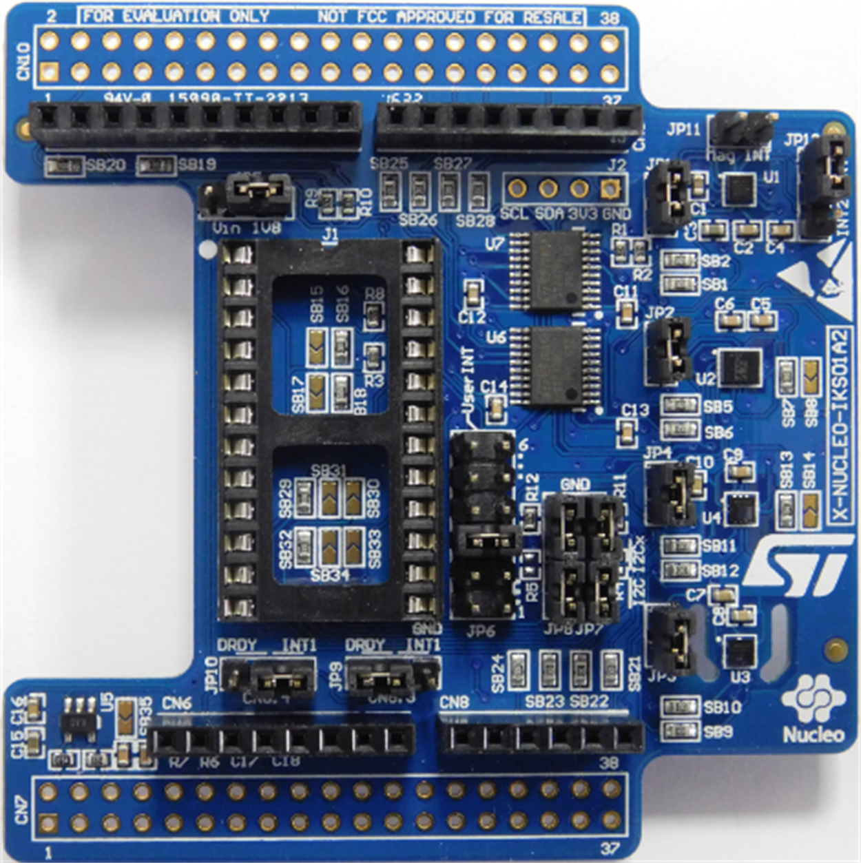
This board is described in more detail since a project is given in this section which displays the current humidity, temperature, and atmospheric pressure. The X-NUCLEO-IKS01A2 expansion board is equipped with jumpers which allow separate current consumption measurement of each sensor. An additional sensor can be connected as an adapter board to J1 DIL24 socket.
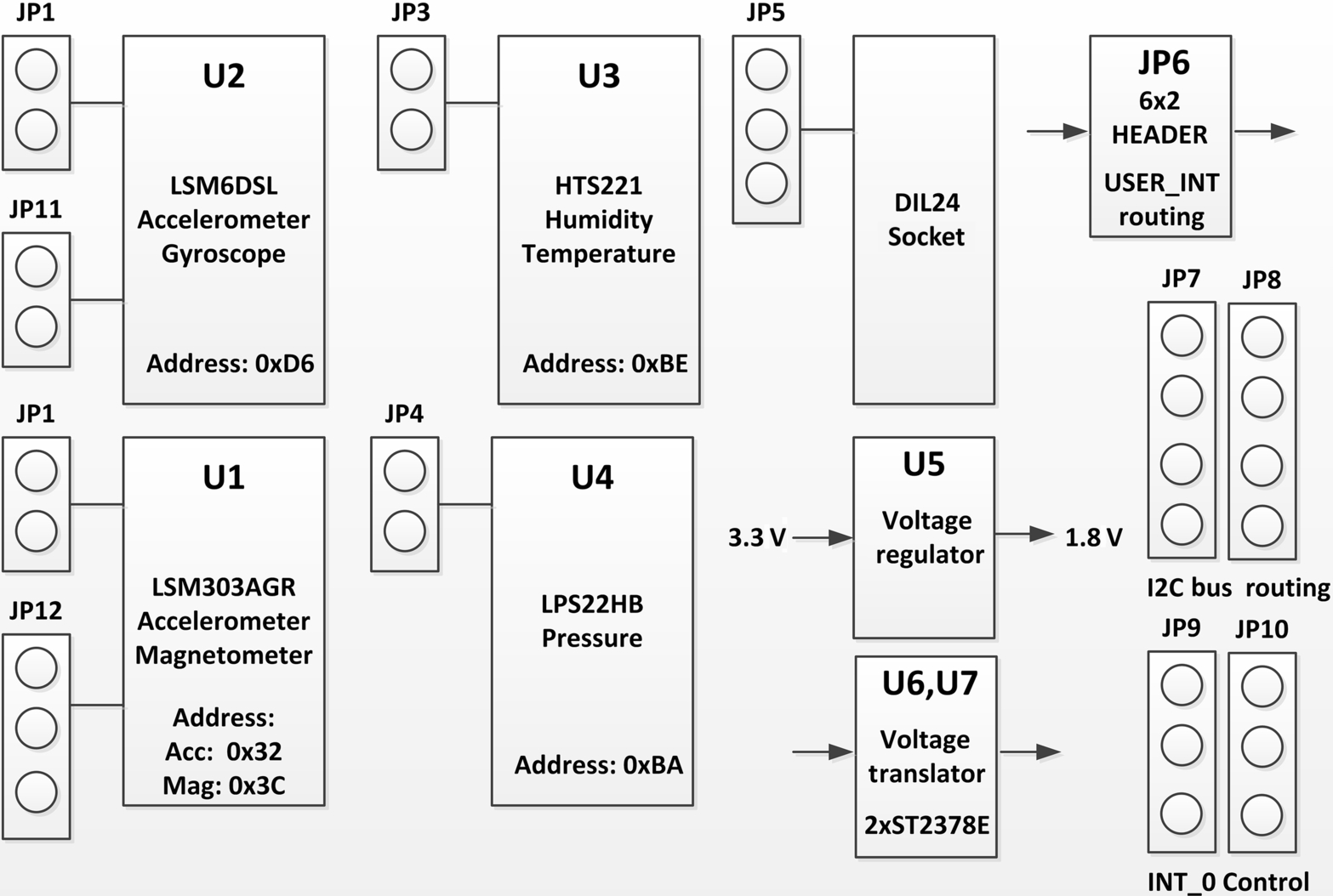
The board functional block diagram is shown in Fig. 17.5. There are a number of jumpers that can be used to configure the various modules on the board. All the modules on the board are configured to operate as I2C slaves by default (JP7: 1, 2, 3, 4 connected, also JP8: 1, 2, 3, 4 connected) and they all share the same bus. The module I2C default addresses are shown in Fig. 17.5 and are repeated below for convenience:
17.6 Project 1—Measuring and Displaying the Humidity, Temperature, Atmospheric Pressure, and Dew Point Using the X-NUCLEO-IKS01A2 Expansion Board
17.6.1 Description
In this project an X-NUCLEO-IKS01A2 expansion board is plugged on the Nucleo-F411RE development board. The project measures the ambient humidity, temperature, and the atmospheric pressure. The dew point is calculated from knowledge of the humidity and temperature. All the four parameters are displayed on the PC screen every 15 s.
17.6.2 Aim
The aim of this project is to show how the X-NUCLEO-IKS01A2 expansion board can be used in a project.
17.6.3 Pin Configuration
X-NUCLEO-IKS01A2 expansion board pin configuration is shown in Fig. 17.6.

17.6.4 Program Listing
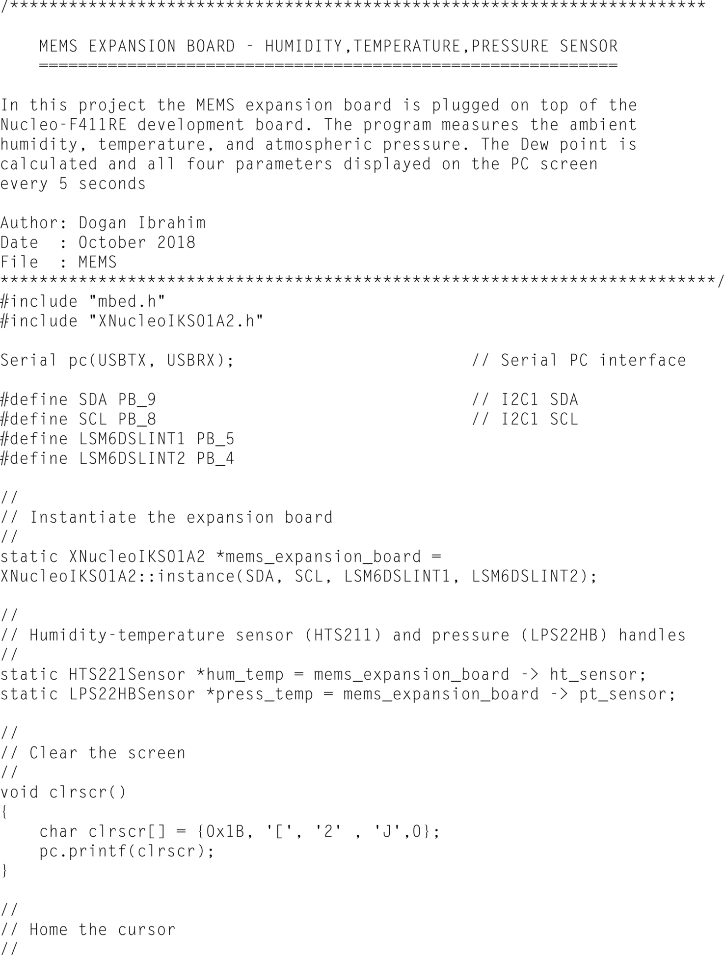
The program listing (program: MEMS) is shown in Fig. 17.7. The Mbed library XNucleoIKS01A2 must be included in the program before the MEMS library functions can be used. Open a new Mbed session with program name MEMS, and click on Import Library and Click Select Path then select MEMS as the program name to include the library folder in the program space. The library is available at the following website:

https://os.mbed.com/components/X-NUCLEO-IKS01A2/
At the beginning of the program header files mbed.h and XNucleoIKS01A2.h are included in the program. The PC serial interface and the interface between the expansion board and the development board are then defined. The handles for the humidity-temperature and pressure sensors are defined. Inside the main program the humidity-temperature sensor and pressure sensor modules are enabled. The program then enters an endless loop created using a while statement. Inside this loop the humidity, temperature, and pressure are read from the expansion board and stored in floating point variables humidity, temperature, and pressure, respectively. The dew point is calculated using the following formula by Magnus:
where Ln is the logarithm to base 2, RH is the relative humidity as a percentage, T is the ambient temperature in degree Centigrade, Dew Point is in degree Centigrade, and b and c are the following constants:
For example, if RH = 10%, T = 25°C then the dew point is
or
which gives, Dew Point = − 8.72°C
A heading is displayed followed by all the four parameters. The display is repeated every 15 s. Fig. 17.8 shows a typical display from the program.

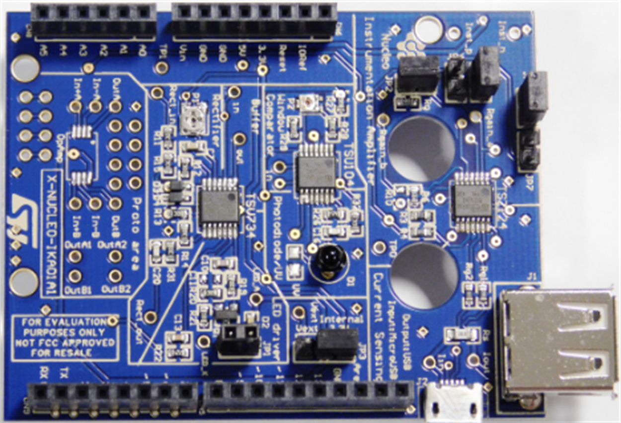
17.7 Multifunctional Expansion Board (X-NUCLEO-IKA01A1)
This expansion board (Fig. 17.9) is based on operational amplifiers which can be used as an analog front end. The board contains a micropower and nanopower operational amplifiers. The basic features of this expansion board are as follows:
- • seven predefined configurations: instrumentation amplifier, current sensing photodiode, ultraviolet current sensing, buffer, full wave rectifier, constant current LED driver, window comparator
- • prototyping area on board
- • Arduino UNO R3 connector compatible
17.8 Bluetooth Low-Energy Expansion Board (X-NUCLEO-IDB04A1)
This is a Bluetooth low-energy expansion board (Fig. 17.10) which interfaces with the Nucleo development boards via SPI bus. The board enables Bluetooth communication with other Bluetooth compatible devices. The basic features of this board are as follows:
- • Bluetooth low-energy 4.0 master and slave compliant
- • equipped with Arduino Uno R3 connector
- • low-power consumption (7.3 mA RX and 8.2 mA TX)
- • + 8 dBm maximum transmission power
- • − 88 dBm receiver sensitivity

17.9 Three-Phase Brushless DC Motor Board (X-NUCLEO-IHM07M1)
This is a three-phase brushless DC motor expansion board (Fig. 17.11) based on the DMOS fully integrated driver L6230. The board enables three-phase brushless DC motor to be controlled from the Nucleo development boards. Overcurrent and thermal protection are provided and the driver is optimized for six-step and FOC algorithms. The basic features of this expansion board are as follows:
- • 8–48 V operating voltage
- • three-phase BLDC/PMSM motor driver
- • 100 kHz operating frequency
- • overcurrent and thermal protection
- • motor current sensing
- • Hall/encoder sensor connector and circuit
- • potentiometer for speed regulation
- • user LED

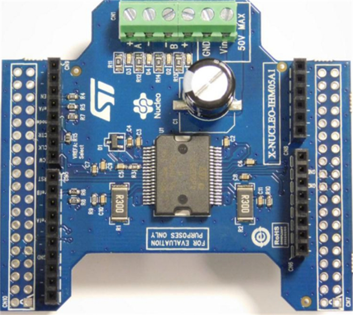
17.10 Bipolar Stepper Motor Driver Board (X-NUCLEO-IHM05A1)
This is a bipolar stepper motor driver expansion board (Fig. 17.12) based on the L6208 driver. The board is compatible with the Arduino UNO R3 connector. Its basic features are as follows:
- • 8–50 V operation
- • up to 2.8 A rms phase current
- • dual independent PWM current controllers
- • full and half step drive
- • fast and slow decay mode selection
- • overcurrent and thermal protection
17.11 Low-Voltage Stepper Motor Driver Expansion Board (X-NUCLEO-IHM06A1)
This is a low-voltage stepper motor driver expansion board (Fig. 17.13) based on the STSPIN220. The board can be operated with battery and is suitable for applications such as robotics, toys, and thermal printers. The board offers a maximum 1/256 microstep resolution and is Arduino UNO R3 connector compatible. The basic features of this board are as follows:
- • 1.8–10 V operation
- • up to 1.3 A rms phase current
- • up to 256 step microstep adjustments
- • overcurrent, short-circuit, and thermal shutdown protection
- • current control with adjustable off-time

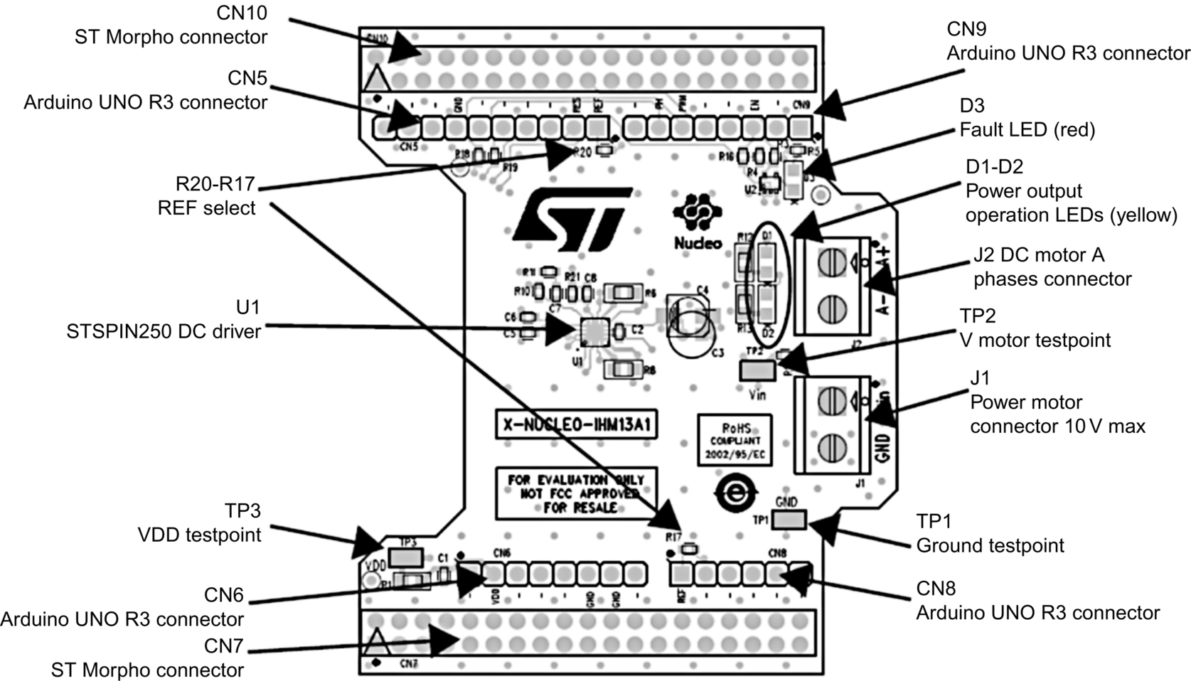
17.12 Brushed DC Motor Driver Expansion Board (X-NUCLEO-IHM13A1)
This is a low-voltage brushed DC motor driver expansion board (Fig. 17.14) based on the STSPIN250 driver. The board is compatible with the Arduino UNO R3 connector. The basic features of this board are as follows:
- • 1.8–10 V operation
- • up to 2.6 A rms current
- • overcurrent, short-circuit, and thermal shutdown protection
- • current control with adjustable off-time

This board is described in more detail since two projects are given in this section using this board. The board component layout is shown in Fig. 17.15. Motor voltage (10 V maximum) is applied to connector J1, while the motor pins are connected to connector J2. An external power supply should be used to provide power to the motor. When power is applied through jumper J1 the red LED turns ON.
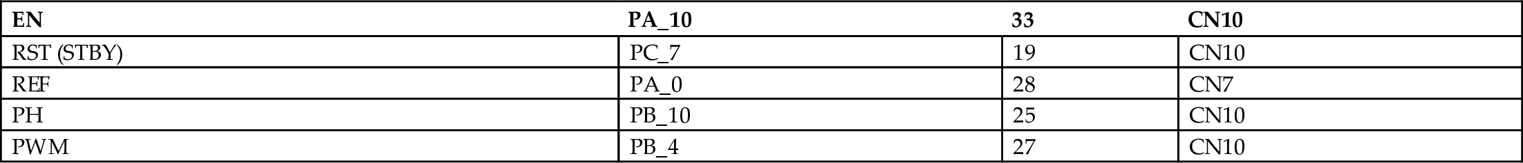
The following pins are used to control the board:
- EN: Power enable input (logic HIGH to enable)
- RESET: Reset
- REF: Reference voltage for the current limiter circuit
- PH: Logic input that determines the direction of rotation
- PWM: Pulse Width Modulated input (logic HIGH to operate)
These pins are connected to the following Nucleo development board pins on the ST Morpho connector:
17.13 Project 2—Brushed DC Motor Speed Control Using the X-NUCLEO-IHM13A1 Expansion Board
17.13.1 Description
In this project an X-NUCLEO-IHM13A1 expansion board is used with a small brushed DC motor. This is a simple project where the motor initially starts rotating for 10 s with 50% of its full speed. Then, full speed is applied for 10 s. The motor is then stopped for 10 s, and full speed is applied for 10 s in the reverse direction. After this time the motor is stopped. The above process continues forever until stopped manually by the user.
17.13.2 Aim
The aim of this project is to show how the X-NUCLEO-IHM13A1 expansion board can be used in a project to control the speed of a small brushed DC motor.
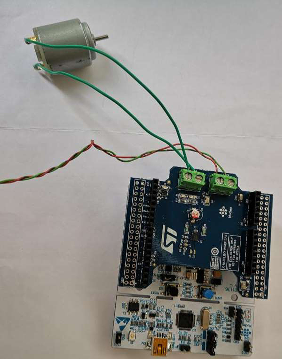
17.13.3 The Construction
The expansion board was plugged on top of the development board, a small DC motor was connected to screw terminal J2, and external + 5 V power supply was connected to screw terminal J1. Fig. 17.16 shows the project components.
17.13.4 Program Listing
The X-NUCLEO-IHM13A1 expansion board is not supported by the Nucleo-F411RE development board. Therefore, in this project a board similar to Nucleo-L476RG development board is used which is fully supported by this expansion board. The pin configurations of the two development boards are identical. It is important that board Nucleo-L476RG must be selected before compiling and downloading the program.
The program listing (program: BMotor) of the project is shown in Fig. 17.17. The Mbed library X-NUCLEO-IHM12A1 must be included in the program from the following website:
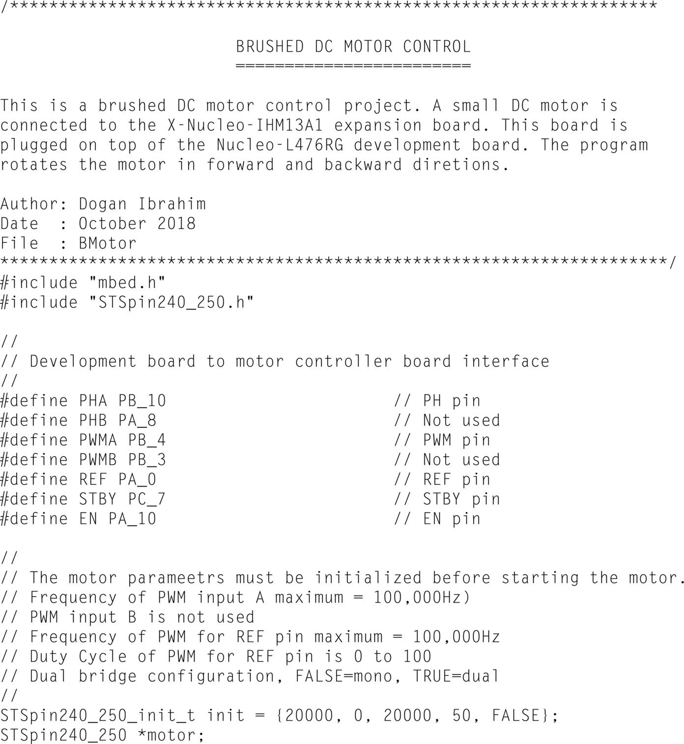
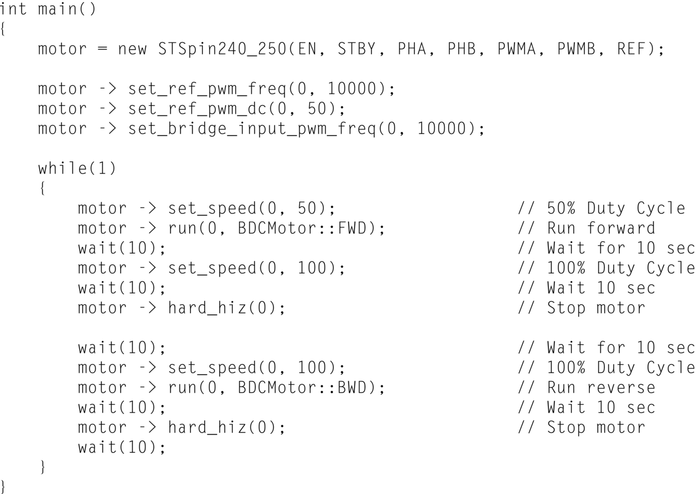
Click Import Library as described in the previous project to download the library. Although this library is for the X-NUCLEO-IHM12A1 dual motor controller expansion board, it can also be used for the X-NUCLEO-IHM13A1 board when it is configured for single motor application.
At the beginning of the program header files mbed.h and STSpin240_250.h are included in the program. Then, the interface between the expansion board and the development board are defined. Notice that although the library supports dual DC motors, in this project only a single motor is used and parameters for the second motor (PHB and PWMB are not used). Inside the main program the actual connections to the expansion board are defined with motor being declared a new class. Initially the PWM frequency is set to 10,000 Hz and the Duty Cycle to 50%. The remainder of the program runs in an endless loop created using a while statement. Inside this loop, the Duty Cycle is set to 50%, motor is configured to run in forward direction (BDCMotor::FWD) for 10 s. The Duty Cycle is then set to 100% and the motor runs a further 10 s. At this point the motor stops for 10 s. Then, the motor is configured to run for 10 s in backward direction (BDCMotor::BWD) with 100% Duty Cycle. The above process is repeated forever until stopped by the user.
17.14 Project 3—Brushed DC Motor Speed Control Using a Potentiometer With the X-NUCLEO-IHM13A1 Expansion Board
17.14.1 Description
In this project an X-NUCLEO-IHM13A1 expansion board is used with a small brushed DC motor. A potentiometer is connected to the Nucleo-L476RG development board. The speed of the motor is varied from 0% to 100% by moving the potentiometer arm.
17.14.2 Aim
The aim of this project is to show how the X-NUCLEO-IHM13A1 expansion board can be used in a project to control the speed of a small brushed DC motor.
17.14.3 Block Diagram
The block diagram of the project is shown in Fig. 17.18. The expansion board is plugged on top of the development board via the Arduino UNO R3 connectors.

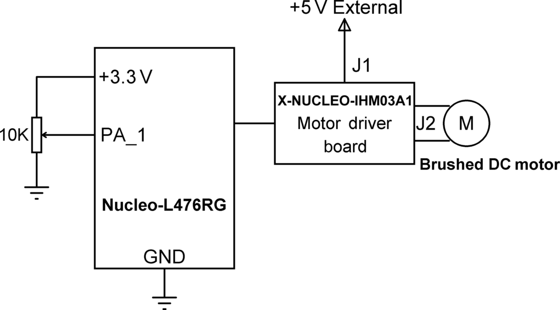
17.14.4 Circuit Diagram
Fig. 17.19 shows the project circuit diagram. The arm of A10K linear potentiometer is connected to analog input PA_1 of the Nucleo-L476RG development board. The other two terminals of the potentiometer are connected to + 3.3 V and GND pins of the development board.
17.14.5 Program Listing
The program listing (program: PotMotor) is shown in Fig. 17.20. Analog voltage of the potentiometer is read into variable pot. The value read is a floating point variable between 0 and 1.0, where 0 corresponds to 0 V and 1.0 corresponds to the ADC reference voltage of + 3.3 V. Variable pot is multiplied with 100 to convert it into Duty Cycle between 0% and 100%. This value is then used to control the speed of the motor such that as the potentiometer arm is rotated the motor speed changes from 0% to 100%. Make sure that you compile for the Nucleo-L476RG development board.


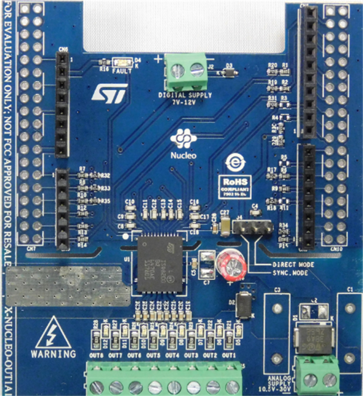
17.15 Industrial Digital Output Expansion Board (X-NUCLEO-OUT01A1)
This is an industrial output expansion board (Fig. 17.21) based on the galvanic octal power solid-state relay ISO8200BQ. The board provides eight relay-based outputs with LED indicators. The maximum output current per output channel is 700 mA.
The basic features of this expansion board are as follows:
- • operating voltage 10.5–33 V
- • galvanic isolated outputs
- • 700 mA output current per channel
- • thermal protection
- • Arduino UNO R3 compatible connector
This board is described in more detail since a project is given in this section using this board. As shown in Fig. 17.21, an eight-way screw-type connector is provided at the bottom part of the board for making the output connections. Just above these connectors are the eight LEDs. At the top middle part of the LED a two-way screw connector (J2) is provided for applying external voltage (7–12 V) if the board is to be operated, for example, with a battery. An external 10.5–33 V DC voltage must be connected to the two-way screw terminal J1, located at the bottom right-hand corner of the board.
The X-NUCLEO-OUT01A1 expansion board has eight inputs, labeled IN1 to IN8 that correspond to the eight outputs. Jumper J4 selects the mode of operation as SYNC or DIRECT. For DIRECT mode this jumper must be connected to GND, and for SYNC mode the jumper must be connected to + 3.3 V. In DIRECT mode each input INi drives its corresponding output OUTi. The ISO8200BQ has an input buffer and a transmission buffer. The board is controlled by three signals named as LOAD, SYNC, and OUT_EN. OUT_EN must be set to logic HIGH to enable the channel outputs. LOAD input, when LOW, loads the input data into the input buffer. SYNC input, when LOW, copies contents of the input buffer to the transmission buffer and it can be used to synchronize the low-voltage side and the channel outputs on the isolated high-voltage side. In normal operation (DIRECT mode), LOAD and SYNC inputs are set to logic LOW, and the OUT_EN input is set to logic HIGH.
Fig. 17.22 shows the connections between the expansion board and the Nucleo development board. The pins of interest are as follows:

| Expansion Board Signal | Nucleo Board Pin |
|---|---|
| IN1 | PA_0 |
| IN2 | PA_1 |
| IN3 | PA_3 |
| IN4 | PA_4 |
| IN5 | PB_4 |
| IN6 | PB_5 |
| IN7 | PB_9 |
| IN8 | PB_8 |
| LOAD | PC_0 |
| SYNC | PC_1 |
| OUT_EN | PB_0 |
A simplified block diagram of the X-NUCLEO-OUT01A1 expansion board is shown in Fig. 17.23.

17.16 Project 4—Controlling LEDs With the X-NUCLEO-OUT01A1 Expansion Board
17.16.1 Description
In this project an X-NUCLEO-OUT01A1 expansion board is plugged on top of the Nucleo-F411RE development board. The LEDs on the expansion board are turned ON or OFF by entering commands in the form of hexadecimal numbers on the PC screen. For example, command 03 turns ON the two LEDs at the right-hand side of the LEDs, command 0F turns ON all four lower LEDs, command FF turns ON all the LEDs, and so on.
17.16.2 Aim
This is a very simple project. The aim of this project is to show how the X-NUCLEO-OUT01A1 expansion board can be used in a project with a Nucleo development board.
17.16.3 Circuit Diagram
The X-NUCLEO-OUT01A1 expansion board uses GPIO pin PA_3 for its channel 3 (IN3) input. But unfortunately PA_3 and PA_2 on the Nucleo development board are used as the USB serial port RX and TX signals of USART2, respectively (i.e., USBTX is same as PA_2 and USBRX is same as PA_3). If the boards are used as they are then channel 3 (OUT3) will not respond since its corresponding input pin IN3 cannot be controlled by the software. It is therefore necessary to redirect the USB serial port to another UART on the Nucleo board so that pin PA_3 becomes available as a general purpose digital pin.
The steps given below describe how the USB serial port can be changed to use USART 1 with pins PA_9 as the TX and PA_10 as the RX, respectively. Notice that these changes require two jumpers (also called solder bridges) to be disconnected and two other jumpers to be connected at the bottom part of the Nucleo PCB board. These jumpers are tiny and require very careful de-soldering and soldering. You should not attempt to make these changes if you are not confident of soldering very small parts as you may easily damage the board:
- • Fig. 17.24 shows the jumpers at the bottom part of the Nucleo PCB board.
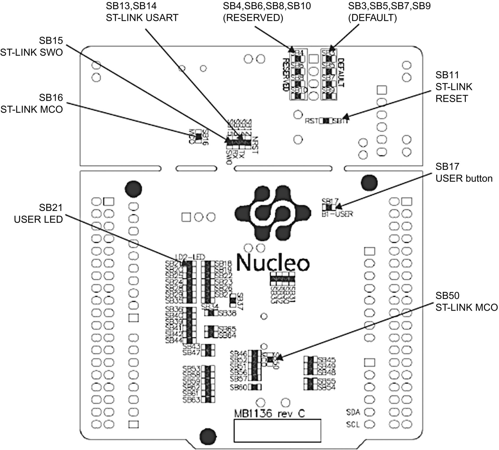
Fig. 17.24 Jumpers at the bottom part of the PCB. - • The function of these jumpers are listed in Table 10 of the following STM User Manual:
- • USART2 pins PA_3 and PA_2 of the processor are by default the USB serial RX and TX pins, respectively, for connecting to a PC. As shown in Fig. 17.25, these pins are connected to the Arduino Uno R3 pins D0 and D1 (or to the PA_3 and PA_2 on ST Morpho connector CN10), respectively, on connector CN9, through jumpers SB62 and SB63. But, these jumpers are by default OFF and as a result there are no connections from the processor PA_3 and PA_2 pins to the connectors. What we need to do is solder wires to jumpers SB62 and SB63 so that there is connection from the processor to the connectors.

Fig. 17.25 Jumpers SB62 and SB63. - • Jumpers SB13 and SB14 (Fig. 17.26) are by default ON and provide the ST-LINK USB serial link from the processor PA_3 and PA_2 pins to the ST-LINK processor. We have to make both these jumpers OFF so that there is no link between the processor PA_3 and PA_2 pins.

Fig. 17.26 Jumpers SB13 and SB14. - • We now have to connect jumper wires from the USART1 pins PA_9 and PA_10 to pins RX and TX of connector CN3 (see Fig. 17.26), respectively. These connections make USART1 to be the USB serial port. CN3 is located at the top left-hand side of the Nucleo board. Notice that PA_9 and PA_10 can be accessed from pin 1 of Arduino connector CN5 and pin 3 of Arduino connector CN9, respectively.
- • The Nucleo board is now ready so that USART1 is the USB serial interface to a PC.
Remember to undo the above jumper changes if you wish to use USART2 (i.e., USBTX and USBRX) for USB serial interface.
An external 12 V DC voltage must also be connected to jumper J1 which is a two-way screw terminal located at the bottom right-hand side of the board.
17.16.4 The Construction
Fig. 17.27 shows the jumper wires for the USART1 connection.

17.16.5 Program Listing
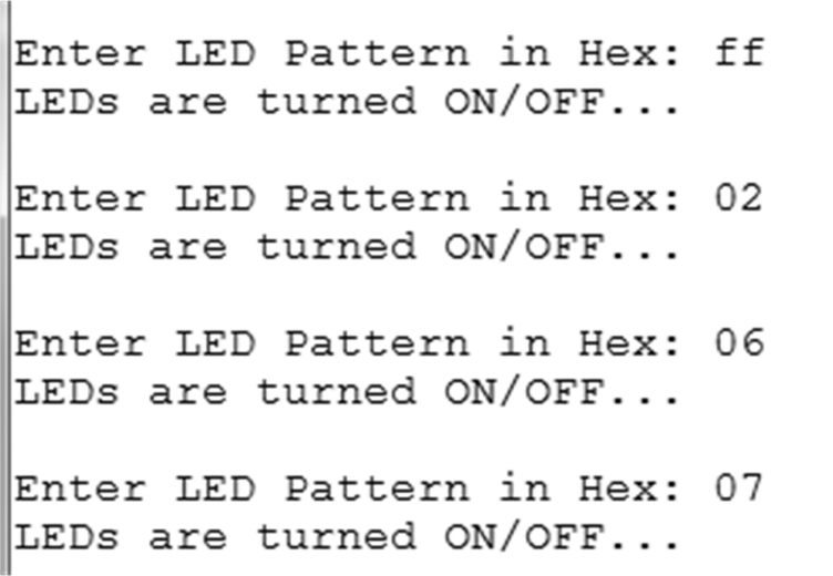
The program listing (program: OUT01A1) is shown in Fig. 17.28. At the beginning of the program the BusOut statement is used to group the eight channels into a variable called LEDS. The USB serial PC interface is then defined where PA_9 is the TX and PA_10 is the RX pin, respectively. Inside the main program LOAD and SYNC are set LOW and OUT_EN is set HIGH so that the expansion board is ready. The remainder of the program runs in an endless loop where the user is prompted to enter the required LED pattern as a hexadecimal number. The required LEDs are then turned ON or OFF. Fig. 17.29 shows a typical output from the program. Here, for example, entering ff (binary: 1111 1111) turns all the LEDs ON, 02 (binary: 0000 0010) turns the second LED from the right-hand side ON, 06 (binary: 0000 0110) turns ON the second and third LEDs from the right-hand side, and so on. Notice that when an LED is turned ON the relay at the corresponding output channel is activated.

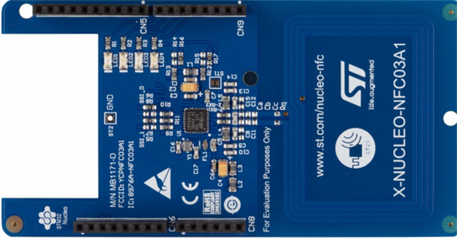
17.17 CR95HF NFC Card Reader Expansion Board (X-NUCLEO-NFC03A1)
This is an NFC card reader expansion board based on the CR95HF integrated circuit. The board can be used with a Nucleo board in security-based contactless tag applications, such as secure door entry, user identification, etc. The board provides 13.56 MHz interface to compatible NFC cards and communicates with the Nucleo boards through UART or SPI interface. The basic features of this expansion board are as follows (Fig. 17.30):
- • Onboard 13.56 MHz inductive antenna supports ISO/IEC 14443 Type A and B, 15693, and 18092 communication protocols
- • Detection, reading, and writing of NFC Type 1, 2, 3 and 4 tags
- • Four general purpose LEDs
- • Arduino UNO R3 compatible connectors
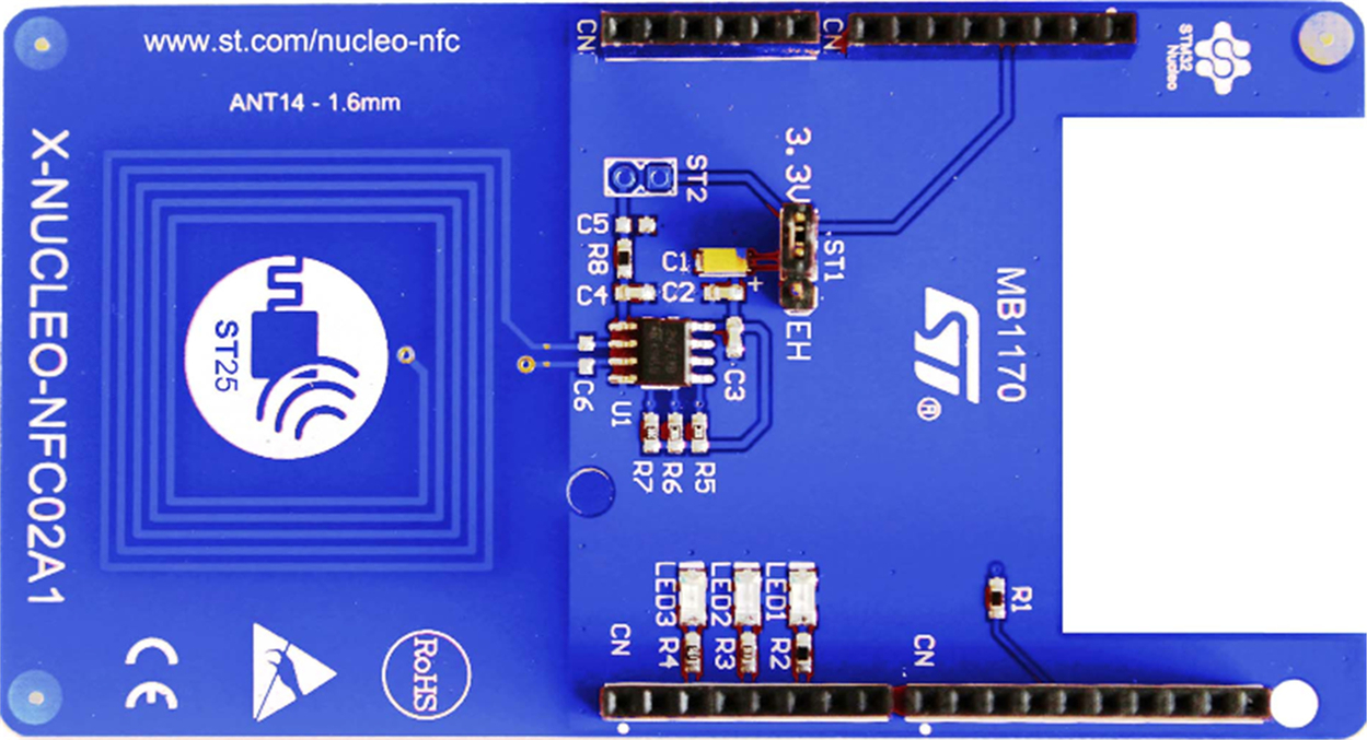
17.18 M24LR Dynamic Tag Expansion Board (X-NUCLEO-NFC02A1)
This is a dynamic NFC/RFID tag expansion board (Fig. 17.31) based on M24LR. It contains a 512 8 bit EEPROM in I2C mode and 128 × 32 bit in RF mode. The board interfaces with the Nucleo boards via the I2C interface and is Arduino UNO R3 connector compatible. The basic features of this expansion board are as follows:
- • Up to 4 kbit memory
- • Onboard 13.56 MHz inductive antenna
- • Three general purpose LEDs
- • Multiple boards can be cascaded for larger systems
- • Self-powered or powered from the Nucleo boards
17.19 Ranging and Gesture Detection Sensor Expansion Board (X-NUCLEO-53L0A1)
This is a ranging and gesture detection sensor expansion board (Fig. 17.32) based on ST’s Flight Sense (time-of-flight technology). This board provides an introduction to the ranging and gesture detection capabilities of the VL53L0X module. The board is compatible with the Arduino UNO R3 connectors. To allow the user to validate the VL53L0X in an environment as close as possible to its final application, the X-NUCLEO-53L0A1 expansion board is delivered with a cover glass holder in which three different spacers of 0.25, 0.5, and 1 mm height can be fitted below the cover glass in order to simulate various air gaps. Two VL53L0X satellites can be connected using the two 10-pin connectors. The basic features of this expansion board are as follows:
- • VL53L0X ranging and gesture detection sensor module.
- • Accurate absolute ranging distance, independent of the reflectance of the target.
- • Four-digit display, displaying the distance of a target from the ranging sensor.
- • Basic gesture recognition application can be developed with a VL53L0X module.
- • Cover glass.
- • Two VL53L0X satellite boards.
- • Two 10-pin connectors for VL53L0X satellite boards.
- • Four-digit onboard seven-segment LED display.

This board is described in more detail since a project is given in this section using this board. The pin layout of this expansion board is shown in Fig. 17.33. The interface between the expansion board and the Nucleo development board is via I2C.

17.20 Project 5—Measuring Distance to an Object Using the X-NUCLEO-53L0A1 Expansion Board
17.20.1 Description
In this project an X-NUCLEO-OUT01A1 expansion board is plugged on top of the Nucleo-F411RE development board. The project measures the distance in millimeters to an object in-front of the expansion board and displays the result on the PC screen.
17.20.2 Aim
This is a very simple project. The aim of this project is to show how the X-NUCLEO-53L01A1 expansion board can be used in a project with a Nucleo development board.
17.20.3 Program Listing
Library Xnucleo53L01A1 must be downloaded to the program space before the board can be used. This is available at the following website:https://os.mbed.com/components/X-NUCLEO-53L0A1/
Create a new Mbed program, for example, called Sonar. Open the above website and click Import Library. Then select Sonar by clicking on Target Path to download the library to your program space. Fig. 17.34 shows the program listing. At the beginning of the program header files mbed.h and XNucleo53L01A1.h are included in the program and the I2C interface between the expansion board and the development board are defined. The program initializes the expansion board and then enters an endless loop. Inside this loop the distance in-front of the expansion board is measured and is displayed in millimeters on the PC screen. The loop repeats after 1 s delay.


A typical display from the program is shown in Fig. 17.35.

17.20.4 Suggestions for Additional Work
Modify the program in Fig. 17.34 to display the distance on the onboard LEDs (see the example program in the X-NUCLEO-53L01A1 Mbed website).
17.21 Summary
In this chapter we have learned about the following:
- • Information on commonly used Nucleo expansion boards
- • Measuring humidity, temperature, and atmospheric pressure using an expansion board
- • Controlling the speed of a small brushed DC motor using an expansion board
- • Using the industrial I/O expansion board in a project
- • Using the ranging and gesture detection sensor expansion board in a project
17.22 Exercises
- 1. Describe the advantages of using an expansion board in a project.
- 2. A motion MEMS expansion board is plugged on top of a Nucleo-F411RE development board. Write a program to read and display the acceleration on the PC screen as the board moves.
- 3. A motion MEMS expansion board and an LCD are connected to a Nucleo-F411RE development board. Write a program to read and display the relative humidity on the LCD every 5 s.
- 4. A brushed DC motor is connected to the expansion board X-NUCLEO-IHM13A1 which is plugged on top of a Nucleo-F411RE development board. Write a program to run the motor at 25% of its full speed.
- 5. An industrial digital output expansion board is plugged on top of a Nucleo-F411RE development board. Write a program to count up in binary on the LEDs every second.