
Internet of Things (IoT)
Abstract
The Internet of Things (IoT) is a new concept in intelligent automation, monitoring, and control. It is the network of home appliances, vehicles, and any other physical devices connected together with sensors, actuators, and displays, which enables these devices to connect and exchange data. It is estimated that in 2017 there were around 9 billion IoT devices in the world and this number is estimated to grow over 30 billion by 2020. The word “things” in IoT usually refers to devices that have unique identifiers, connected to the Internet to exchange information with each other in real time. Such devices have sensors and/or actuators that can be used to collect data about their environments and to monitor and control these environments as required. This chapter presents the basic features of the IoT and describes the commonly used IoT architectures. Additionally, an IoT home project is given in the chapter.
Keywords
Internet of Things (IoT); IoT architecture; Distributed processors; Shared processor; Common processor; Nucleo-F411RE IoT project
16.1 Overview
Internet of Things (IoT) is currently one of the rapidly expanding uses of embedded processors in smart monitoring and control applications. In this chapter we shall be briefly looking at the principles of the IoT and give the complete design of a simple home IoT system.
16.2 Internet of Things (IoT)
The IoT is a new concept in intelligent automation, monitoring, and control. It is the network of home appliances, vehicles, and any other physical devices connected together with sensors, actuators, and displays, which enables these devices to connect and exchange data. It is estimated that in 2017 there were around 9 billion IoT devices in the world and this number is estimated to grow over 30 billion by 2020.
The word “things” in IoT usually refers to devices that have unique identifiers, connected to the Internet to exchange information with each other in real time. Such devices have sensors and/or actuators that can be used to collect data about their environments and to monitor and control these environments as required. The collected data can be processed locally, or alternatively, it can be sent to centralized servers or the cloud for remote storage and processing.
Some IoT home applications include wireless or Internet connected smart appliances that can be turned on and off remotely using, say, a mobile phone or a tablet. For example, a small device can be used to collect data about temperature, humidity, and atmospheric pressure inside the house. This data can then be accessed at any time and from anywhere, provided there is Internet connectivity. Smart refrigerators can keep track of items stored and place orders automatically through the Internet with little or no interaction from their owners. Smart televisions can learn their owners’ watching habits and inform them when a new show is available. Smart home lighting systems can turn on and off automatically and can change light intensities to adapt to the environment. For example, the light intensity can be reduced automatically in the day to save energy. Tea or coffee makers can turn on automatically when the owner wakes up. Smart smoke detectors can raise alarms in a friendly human voice, describing where the fire is and what actions to take. Smart car parks can inform drivers looking for a space to park and inform them the availability of the closest space. Smart roads can send messages to drivers to inform them about the road and weather conditions. Emergency services can use IoT technology to save lives and improve the environment. For example, gas leakage details can be sent automatically to emergency gas service departments to prevent any explosions or deaths. Forest fires can be detected by early warning IoT systems. There are also many applications of the IoT in the retail industry. For example, purchasing habits of customers can be stored by IoT systems which then inform them of special offers and discounts. IoT systems can be used in airports to inform passengers of flight delays before they leave their homes. Flight tickets and hotels can be booked automatically with simple voice commands. Wearable IoT devices can be used to monitor the health of the users, such as the blood pressure, temperature, heart beats, etc. Health centers can automatically be informed of patients’ locations if a serious condition such as a heart attack is detected. There are many more examples of the use of IoT in present day.
16.2.1 IoT Architecture
There is no standard IoT architecture. An IoT system can make use of any technology to read sensors and send data to users. We can basically define two possible IoT architectures as far as the processor architecture is concerned: distributed processors and common processor.
Fig. 16.1 shows a typical distributed processor based IoT architecture. Here, each IoT device sends its data to local processors using a communication technology, such as Wi-Fi, Bluetooth, or simple RF. The actuators of the IoT devices are also connected to the same processors. These local processors then communicate with a central processor which can, for example, be a PC. The PC can send the data to a cloud so that the IoT devices can be monitored and controlled remotely from anywhere in the world and at any time of the day. Users can access the IoT devices through the Internet using their mobile phones, laptops, or tablets.

There can be several variations of the basic distributed processors architecture. In shared distributed processors architecture shown in Fig. 16.2, a group of IoT devices can share a local processor. This architecture has the advantages that it is simpler and also the cost is less since the local processor count is reduced. The disadvantage of this architecture is that some IoT devices may be located far away from the shared processors and it may not be possible to make direct connections. In this architecture the IoT devices can be connected directly to the local processors with wires and only one wireless communication device can be used.

Fig. 16.3 shows the IoT common processor architecture. Here, all the sensors as well as the actuators are connected to a local common processor using wires. The common processor can then send the collected data to a cloud so that users can access the system from anywhere on Earth and at any time. The users can also access the system locally through the common processor.

16.3 Project 1—Home IoT Project
16.3.1 Description
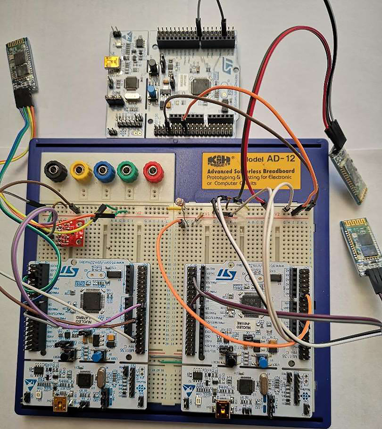
This is a simple home IoT project. In this project three Nucleo-F411RE-type development boards are connected to three Bluetooth modules. One of the development boards (node: IoTTemperature) measures the ambient temperature in the living room through a temperature sensor chip. The second development board (node: IoTLight) measures the light level in children’s room and sends messages ON or OFF to informs the user about the light state. The third development board (called node: IoTWindow) is connected to a switch in the kitchen window and it checks whether or not the window is open and it sends messages OPEN or CLOSED to inform the user about the window state. A PC receives information from all three development boards through Bluetooth and displays this information on the screen every 5 s.
16.3.2 Aim
The aim of this project is to show how a simple IoT project can be developed using Nucleo-F411RE development boards and Bluetooth modules.
16.3.3 Block Diagram
The block diagram of the project is shown Fig. 16.4. The project consists of three development boards, three Bluetooth modules, a temperature sensor chip, a light dependent resistor (LDR), and a switch.

16.3.4 Circuit Diagram
The circuit diagram of the project is shown in Fig. 16.5. Temperature sensor chip TMP102 is connected to I2C port of node IoTTemperature. A LDR is connected to analog input PA_0 of node IoTLight. The LDR resistance is low at daylight and it becomes very high at dark. By measuring the voltage across the LDR we can tell whether the lights are ON or OFF in childrens’ room. A switch mounted on the kitchen window is connected to digital port pin PC_0 of node IoTWindow. Normally the state of this switch is at logic HIGH to indicate that the window is open, and it goes to logic LOW when the window is closed. Bluetooth modules are connected to UART ports of all three development boards so that they can communicate with the PC.

16.3.5 The Construction
Fig. 16.6 shows the project built using three Nucleo-F411RE development boards.
16.3.6 The PDL
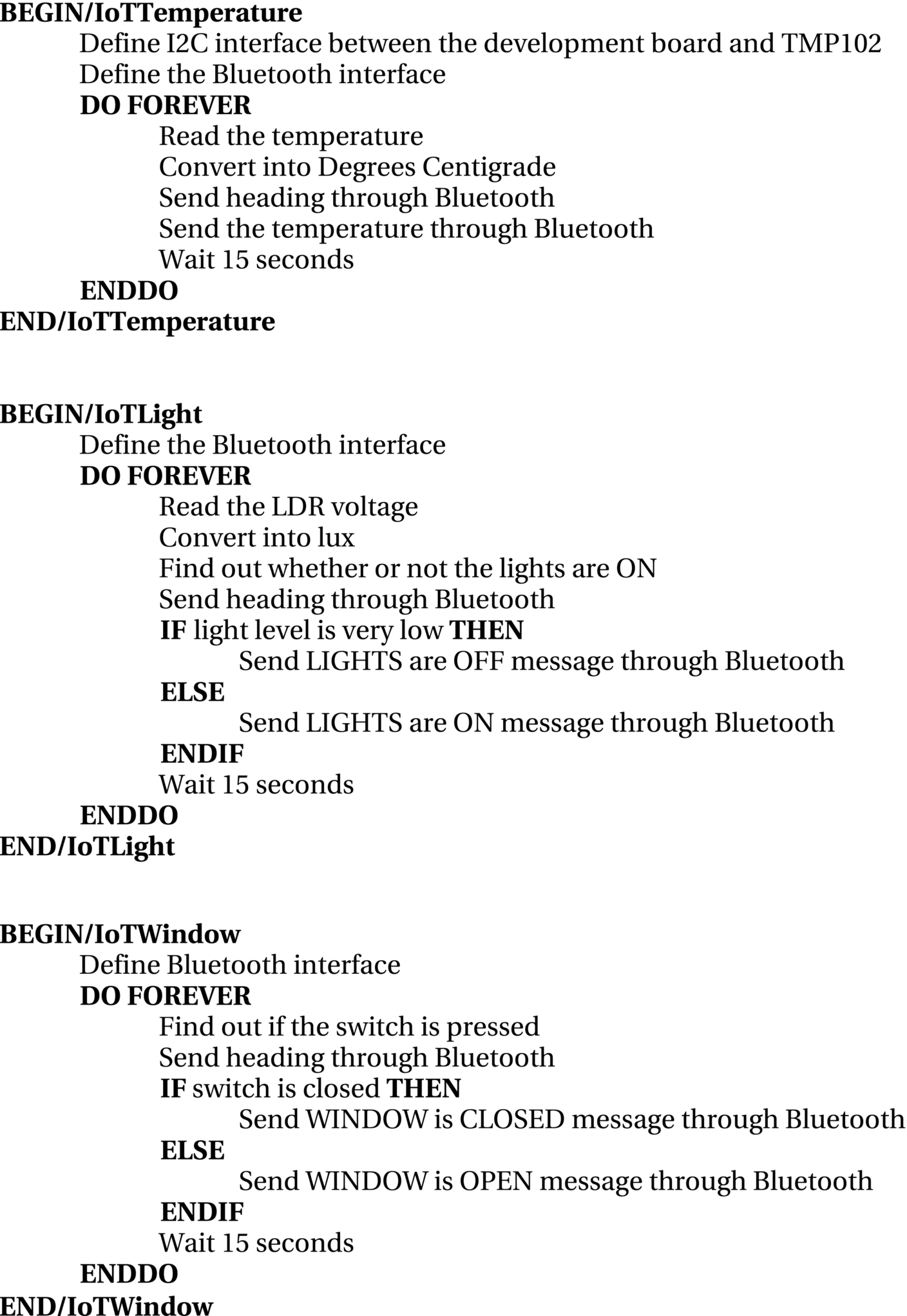
Fig. 16.7 shows the program PDL of each node.
16.3.7 Program Listing
There are three programs in this project, one for each node. Fig. 16.8 shows the program (program: IoTTemperature) for node IoTTemperature. At the beginning of this program the Bluetooth port is defined where TX is PA_9 and RX is PA_10 respectively. The I2C interface between the development board and the TMP102 temperature sensor chip is defined. As explained in Chapter 11, the program reads the ambient temperature. The temperature is converted into degrees Centigrade and is sent through the Bluetooth module every 15 s using statement bluetooth.printf as a floating point data in the format %5.2f, that is, in the form nn.nn.

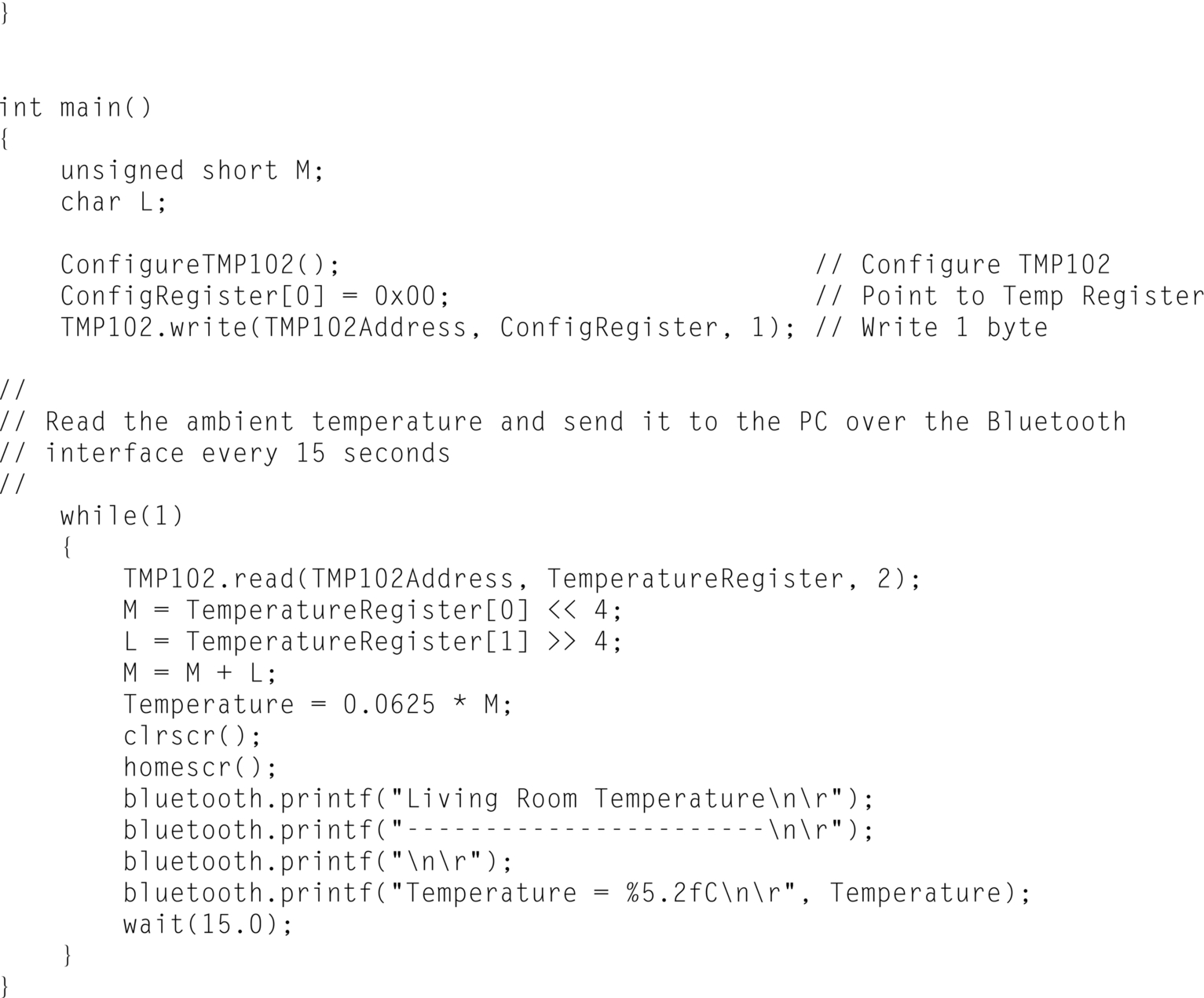
Fig. 16.9 shows the program (program: IoTLight) for node IoTLight. At the beginning of this program the Bluetooth port is defined where TX is PA_9 and RX is PA_10, respectively. PA_0 is used as the analog port to read voltage across the LDR. The light level is converted into lux. It is found by experiment that when the room is dark the light level is below 50. Therefore, the message Lights are OFF is displayed if the room is dark, otherwise message Lights are ON is displayed through the Bluetooth module every 15 s.

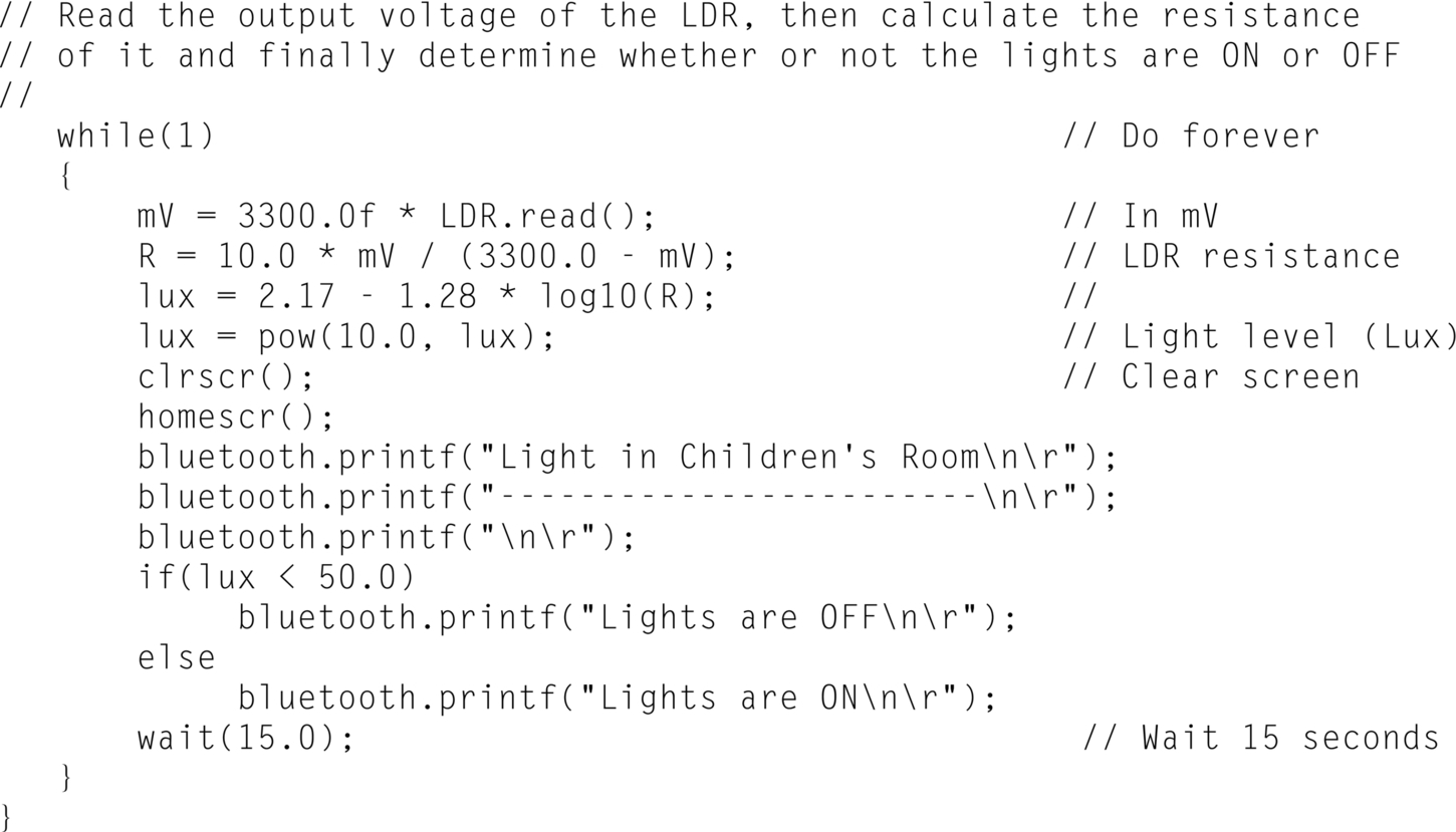
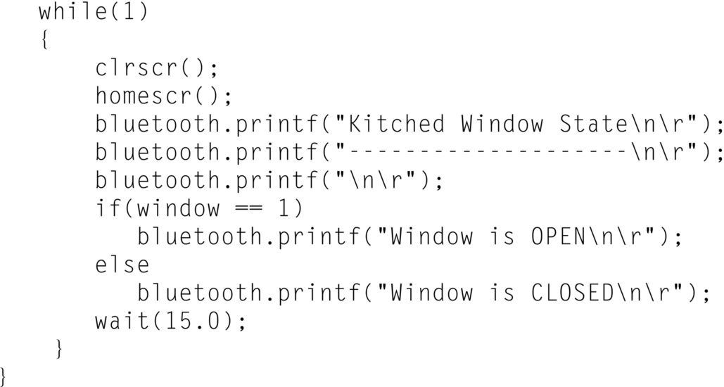
Fig. 16.10 shows the program (program: IoTWindow) for node IoTWindow. At the beginning of this program the Bluetooth port is defined where TX is PA_9 and RX is PA_10, respectively. PC_0 is used as digital input port to read the state of the window switch. If the switch is at logic HIGH then the message Window is OPEN is displayed, otherwise message Window is CLOSED is displayed through the Bluetooth module every 15 s.

16.3.8 Pairing the Bluetooth Modules With the PC
It is necessary to pair the Bluetooth modules with the PC before they can exchange data with the PC. The steps for this are given in the following (these steps are for Window 7.0 operating system, but similar steps should work for other versions of Windows). It is assumed in the following that the Bluetooth modules are attached to all the development boards:
- • Un-plug all development boards from the power supply
- • Enable Bluetooth on your laptop or desktop
- • Plug-in one of the development boards to the power supply
- • Click the Bluetooth icon on your laptop and select Show Bluetooth Devices
- • Click Add a device. You should see HC-06 listed as shown in Fig. 16.11

Fig. 16.11 HC-06 listed. - • Click on HC-06 and then click Next
- • Click on Pair Without Using Code. You should see a message that the device has been added successfully as shown in Fig. 16.12.

Fig. 16.12 Device added successfully. - • Click Close
- • Repeat the above process for the other two development boards. At the end, you should see three HC-06 devices in the Show Bluetooth Devices list.
16.3.9 The PC Program
The TeraTerm terminal emulation program is used in this project for the PC. This emulation program has the option that it can connect to the PC Bluetooth ports and receive or send data through these ports. TeraTerm can be downloaded free of charge from several sources on the Internet.
Before using the TeraTerm we have to know the port addresses of the connected Bluetooth devices. These can be found as follows:
- • Click to open Show Bluetooth Devices
- • Double click on the first listed HC-06 device
- • Click on Hardware and make a note of the COM address. In Fig. 16.13 the COM address is COM53.

Fig. 16.13 Find the COM address. - • Find the COM addresses of the other HC-06 devices as well. In this project they were COM55 and COM57
Now we can display the data received from the development boards on TeraTerm terminals. The steps are as follows:
- • Activate TeraTerm
- • Click Serial
- • Click Port and select COM53: Standard Serial Over Bluetooth as shown in Fig. 16.14

Fig. 16.14 Select port COM53. - • You should see the message A Bluetooth device is trying to connect at the bottom right-hand side of the screen. Click on this message and then enter the default pairing password as 1234 and click Next
- • Click Close
- • Activate two other TeraTerm sessions and enter the other two COM addresses
- • You should now have three TeraTerm windows open
You can see all the TeraTerm windows by clicking on Window and then for example clicking Side by Side in any of the TeraTerm windows. Fig. 16.15 shows the three windows displaying the living room temperature, children’s room lighting, and state of the kitchen window.

16.4 Summary
IoT has become one of the most important topics in the computer industry with an estimated usage of over 9 billion devices by 2017. In this chapter we have learned the following:
- • The IoT concept
- • IoT architectures
- • Example of home IoT system
16.5 Exercises
- 1. What do you understand with the term IoT?
- 2. Name three possible applications of the IoT.
- 3. Describe two applications of the IoT in home automation.
- 4. Draw the block diagram of an IoT system with three sensors and a common processor. Explain how the users can access the data using their mobile devices.
- 5. Explain the advantages of using Wi-Fi in IoT systems.
- 6. What are the disadvantages of using Bluetooth in IoT systems?