
Joint Design
Joints for adhesive bonding must be designed specially for adhesives usage. Starting with a design for another method of fastening and modifying it slightly for adhesive bonding is risky, often leading to undesirable results. The aim of joint design is to obtain maximum strength for a given area of a bond. In designing joints specifically for adhesive bonding, the basic characteristics of adhesives must dictate the design of joints. Adhesive bonds act over surface areas and not a single point. Consequently, the joint should be designed with the objective of minimizing concentration of stress.
Keywords
Stress; joint efficiency; joint design criteria; adhesive joints
7.1 Basic Principles
Joints for adhesive bonding must be designed specially for adhesives. Starting with a design for another method of fastening and modifying it slightly for adhesive bonding is risky, often leading to undesirable results. The aim of joint design is to obtain maximum strength for a given area of a bond. In designing joints specifically for adhesive bonding, the basic characteristics of adhesives must dictate the design of joints. Adhesive bonds act over surface areas and not a single point. Consequently, the joint should be designed with the objective of minimizing concentration of stress.
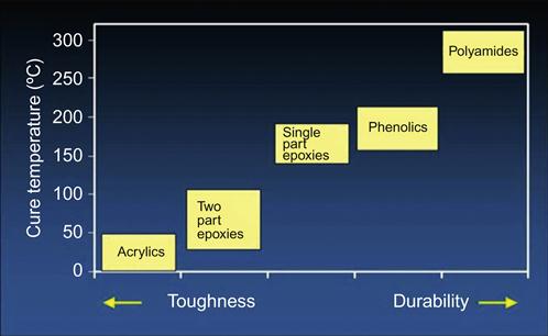
Selection of joint design is influenced by limitations in production facilities, production costs, and the desired final appearance of the part. The strength of an adhesive joint is determined primarily by (1) the mechanical properties of the adherend and the adhesive, (2) the residual internal stresses, (3) the degree of true interfacial contact, and (4) the joint geometry. Each of these factors has a strong influence on joint performance. Figure 7.1 shows the impact of structural adhesive types and cure temperature on the toughness and durability of the bond.
The design engineer must focus on the elimination of stress concentrations, which reduce the strength and useful life of the joint. Localized stresses are not always apparent and may occur as a result of differential thermal expansion of the adhesive and adherends. Another cause is shrinkage of adhesive during cure when volatiles are given off. These volatiles may be entrapped. Internal stresses decrease as adhesive thickness decreases thus reducing the tendency to trap volatiles. Air can also become entrapped at the interface if the adhesive viscosity is too high, does not flow easily as it undergoes curing, or does not wet the substrate [2]. A thorough discussion of metal adhesive joints can be found in Ref. [3].
7.2 Types of Stress
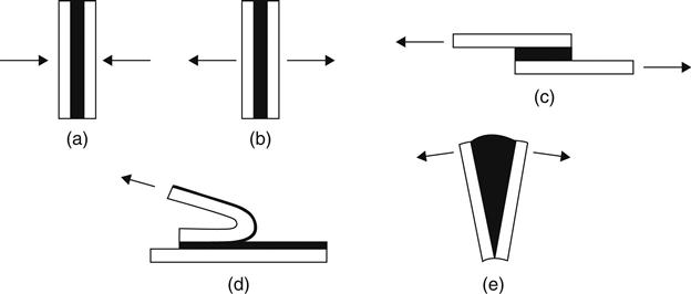
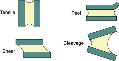
Figure 7.2 shows five types of stress found in adhesive joints. Any combination of these stresses may be encountered in an adhesive application. These stresses are described in the following sections [5].
7.2.1 Compression
When loaded in pure compression, a joint is less likely to fail than when loaded in any other manner, but compression-loaded joints are limited in application.
7.2.2 Shear
This type of loading imposes an even stress across the whole bonded area, utilizing the joint area to the best advantage and providing an economical joint that is most resistant to joint failure. Whenever possible, most of the load should be transmitted through the joint as a shear load [4].
7.2.3 Tension
The strengths of joints loaded in tension or shear are comparable. As in shear, the stress is evenly distributed over the joint area, but it is not always possible to be sure that other stresses are not present. If the applied load is offset to any degree, the advantage of an evenly distributed stress is lost and the joint is more likely to undergo failure. The adherends should be thick with this type of joint and not likely to be deflected to any appreciable degree under the applied load. Such a situation will result in nonuniform stress [4]. Tensile stress develops when forces acting perpendicularly to the plane of the joint are distributed uniformly over the entire area of the bond. The types of stress likely to result when other than completely axial loads are applied are cleavage and peel. As adhesives generally have poor resistance to cleavage and peel, joints designed to load the adhesive in tension should have physical restraints to ensure axial loading [6].
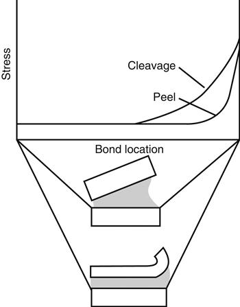
7.2.4 Peel
One or both of the adherends must be flexible in this type of loading. A very high stress is applied to the boundary line of the joint, and unless the joint is wide or the load is small, failure of the bond will occur. This type of loading is to be avoided if possible [4].
7.2.5 Cleavage
Cleavage is somewhat similar to peel and occurs when forces at one end of a rigid bonded assembly act to split the adherends apart [4]. It may be considered as a situation in which an offset tensile force or a moment has been applied. The stress is not evenly distributed (as is the case with tension) but is concentrated on one side of the joint. A sufficiently large area is needed to accommodate this stress, resulting in a more costly joint [4].
7.3 Methods of Improving Joint Efficiency
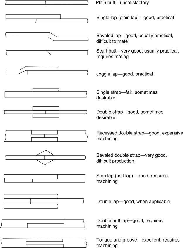
As mentioned earlier, joints should be specifically designed for adhesive bonding. Figure 7.3 illustrates various types of adhesive joints used for flat adherends. Adhesive bonds designed to adopt the following general principles will result in maximum effectiveness [7,8]:
• The bonded area should be as large as possible within the allowable geometry and weight constraints.
• A maximum percentage of the bonded area should contribute to the strength of the joint.
• The adhesive should be stressed in the direction of its maximum strength.
• Stress should be minimized in the direction in which the adhesive is weakest.
Thermosetting adhesives, such as epoxies, are relatively rigid and exhibit high tensile and shear strength under both dynamic loading and static loading. Such adhesives also have good fatigue resistance. However, rigid brittle adhesives are not recommended for bonds stressed in peel or cleavage. Elastomeric adhesives, on the other hand, have low tensile or shear strength, but these adhesives develop high peel or cleavage strength. Adhesives that possess high tensile and shear strength over short periods of static stress give poor results over longer periods or under vibrating stresses [9].
The types of loads and joints that concentrate stresses in small areas or on edges should be avoided. Joints that stress the adhesive in shear are preferable because adhesives generally show considerable strength under this type of stress. Sudden applications of load, such as during impact, require the use of elastic or resilient adhesives to absorb the shock. Brittle adhesives will ordinarily fail under such conditions [9].
7.4 Joint Design Criteria
The bonded area should be large enough to resist the greatest force that the joint will be subjected to in service. The calculation of stress in the adhesive joint is not a reliable way of determining the exact dimensions required. It is relatively difficult to decide on an allowable stress. The strength of the bond is affected by environmental conditions, age, temperature of cure, composition and size of adherends, and the thickness of the adhesive layer [4].
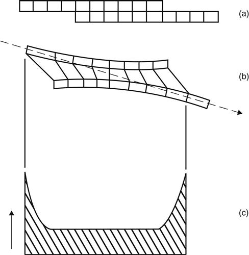
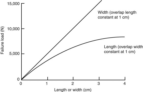
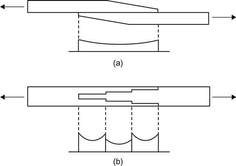
The stress in the adhesive is ordinarily a combination of various stresses. The relative flexibility of the adhesive relative to that of the adherends has a pronounced effect on the stress distribution. Figure 7.4 shows a typical example of a simple lap joint under tensile loading. Figure 7.4(c) shows that most of the stress is concentrated at the ends of the lap. The greater part of the lap (adjacent to the center) carries a comparatively low stress. Therefore, if the overlap length is doubled, the load-carrying capability of the joint is increased by a relatively low percentage. The greatest gain in strength is obtained by increasing the joint width [4].
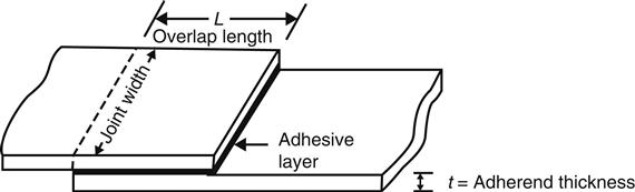
The single lap joint shown in Figure 7.5 is typical of most adhesive joints. Increasing the width of the joint results in a proportionate increase in strength, while increasing the overlap length (L) beyond a certain limit has very little effect, as seen in Figure 7.6 [4].
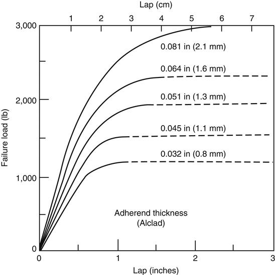
In addition to overlap length and width, the strength of the lap joint is dependent on the yield strength of the adherend. The modulus and thickness of the adherend determine its yield strength, which should not exceed the joint strength. The yield strength of thin metal adherends can be exceeded where an adhesive with a high tensile strength is employed with a relatively small joint overlap. Figures 7.6 and 7.7 show the relationship between shear strength, adherend thickness, and overlap length [4].
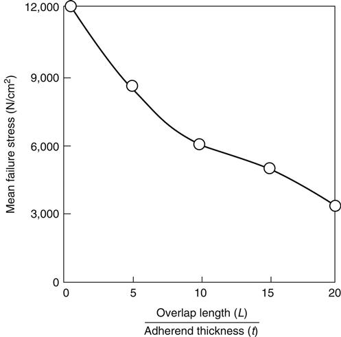
The fall-off in the effective load-bearing capacity of the overlap joint is usually expressed as a correlation between shear strength and the L/t ratio, as seen in Figure 7.7, but sometimes the ratios t/L or t1/2/L are used. The t/L ratio is often called the “joint factor” [4]. Many variables that have significant effects on the strength of an adhesive are related by the L/t curve. Some of these are adherend modulus, adhesive, test temperature, bond line thickness, and joint configuration. The L/t curve is generally used for each variable that may enter the design, and data are presented to the designer as families of L/t curves [9]. One variable commonly plotted is load or stress against L/t.
7.5 Typical Joint Designs
The ideal adhesive-bonded joint is one in which, under all practical loading conditions, the adhesive is stressed in the direction in which it most resists failure. Figure 7.3 shows several types of joints used in bonding flat adherends. These will be discussed briefly [6].
Butt joints. These joints are not able to withstand bending forces because under such forces the adhesive would undergo cleavage stress. If the adherends are too thick to design simple overlap joints, modified butt joints can be designed. Such joints reduce the cleavage effect caused by side loading. Tongue-and-groove joints are self-aligning and provide a reservoir for the adhesive. Scarf butt joints keep the axis of loading in line with the joint and require no extensive machining [6].
Lap joints. These are the most commonly used adhesive joints. They are simple to make, can be used with thin adherends, and stress the adhesive in its strongest direction. The simple lap joint, however, is offset and the shear forces are not in line, as seen in Figure 7.4 [6]. It can be seen in this stress distribution curve that most of the stress (cleavage stress) is concentrated at the ends of the lap. The greater part of the overlap (adjacent to the center) carries a comparatively low stress. If the overlap length is increased by 100%, the load-carrying capability is increased by a much lower percentage. The most effective way to increase the bond strength is to increase the joint width [4]. Modifications of lap joint designs that improve efficiency include [6]:
• Redesigning the joint to bring the load on the adherends in line.
• Making the adherends more rigid (thicker) near the bond area (Figure 7.8).
• Making the edges of the bonded area more flexible for better conformance, thereby minimizing peel.
Modifications of lap joints are shown in Figure 7.3.
Joggle lap joints: This is the easiest design for aligning loads. This type of joint can be made by simply bending the adherends. It also provides a surface to which it is easy to apply pressure [6].
Double lap joints: These joints have a balanced construction that is subjected to bending only if loads in the double side are not balanced [6].
Beveled lap joints: These joints are also more efficient than plain lap joints. The beveled edges allow conformance of the adherends during loading, with a resultant reduction of cleavage stress at the ends of the joint [6].
Strap joints: These joints keep the operating loads aligned and are generally used where overlap joints are impractical because of adherend thickness. As in the case of the lap joint, the single strap is subject to cleavage stress under bending forces. The double strap joint is superior when bending stresses are involved. The beveled double strap and recessed double strap are the best joint designs to resist bending forces. However, both of these types of joints require expensive machining [6].
7.6 Peeling of Adhesive Joints
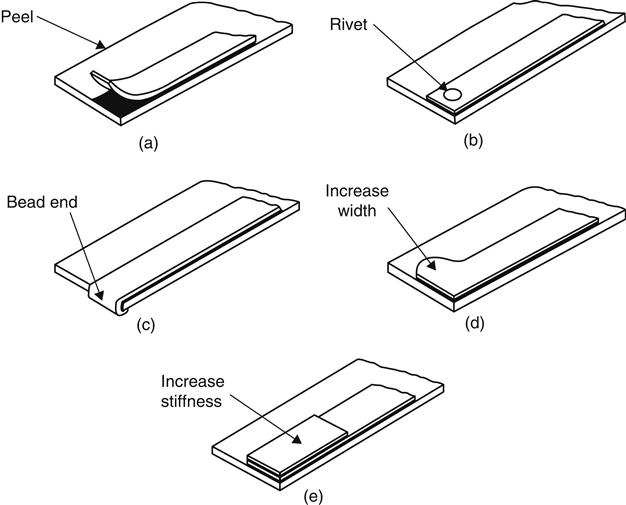
When thin members are bonded to thicker sheets, operating loads generally tend to peel the thin member from its base, as shown in Figure 7.9 [6]. Riveting may provide extra strength at the ends of the bond, but the use of rivets may result in stress concentrations. Beading the end of the joint is helpful, but not always feasible. An increase in peel strength will result from increasing the width of the end of the joint. Finally, increasing the stiffness of the adherends is often quite effective. The stiffer the adherends, the smaller the deflection of the joint for a given force, and the smaller the peel stresses [11].
7.7 Stiffening Joints
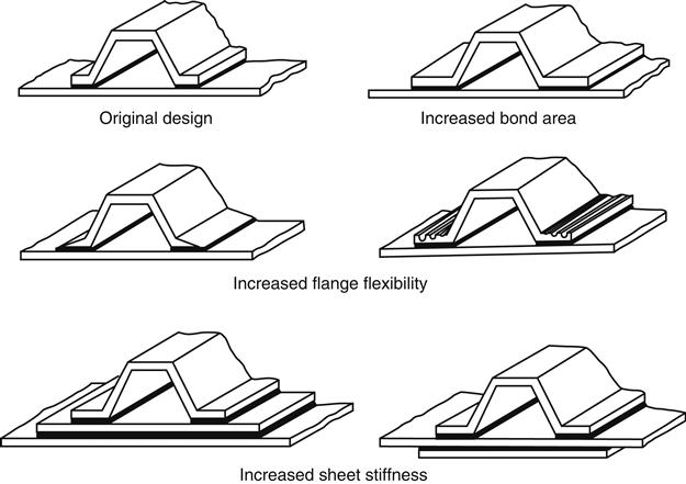
In many cases, thin sheets of adherend are rigidized by bonding stiffening members to the sheet. When such sheets are flexed, the bonded joints are subjected to cleavage stress. Figure 7.10 illustrates design methods used for reducing cleavage stress on stiffening joints.
7.8 Cylindrical Joints
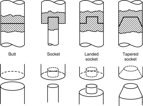
Several recommended designs for rod and tube joints are respectively shown in Figures 7.11 and 7.12. These designs are preferable to simple butt joints because of (1) their resistance to bending forces and subsequent cleavage and (2) their increase in bonding area. In the case of tubular forms (Figure 7.12), the bonding area is small unless the tube walls are very heavy. Most of these joints require a machining operation [6].

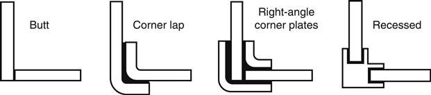
7.9 Angle and Corner Joints
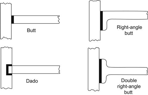
Angle and corner joints for flat adherends are illustrated in Figures 7.13 and 7.14. In both cases, the butt joints are susceptible to cleavage under bending stress. Among the angle joints (Figure 7.13), the dado joint is probably the best, provided that the reduction in section required for the recess is acceptable. This design is less subject to cleavage stress than the right-angle butt joints (also called “L” angle joints) and is easier to form. The double right-angle butt joint is also called the “T” angle joint. Corner joints (Figure 7.14) for flat adherends are best designed to use fixtures. For solid rods and tubular forms, fixtures are always required [11].
7.10 Joints for Plastics and Elastomers
7.10.1 Flexible Materials
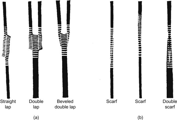
Thin or flexible polymeric substrates may be joined using a simple or a modified lap joint. The double strap joint shown in Figure 7.3 is best but time-consuming to form. The strap material should be fabricated from the same material as for the parts to be joined. If this is not possible, it should have approximately equivalent strength, flexibility, and thickness. The adhesive should have the same degree of flexibility as the adherends. If the sections to be bonded are relatively thick, a scarf joint, also shown in Figure 7.3, is acceptable. The length of the scarf should be at least four times the thickness, as shown in Figure 7.15 [6].

Figure 7.16 shows several types of joints for rubber under tension. The horizontal white lines are equidistant when the joints are unstressed. It is obvious that the scarf joint is least subject to stress concentration with materials of equal modulus, and the double scarf joint is the best for materials of unequal modulus. These designs offer the best resistance to peel and, all other factors being equal, represent the best choices [11].
When bonding elastic material, forces on the elastomer during cure should be carefully controlled, as too much pressure will cause residual stresses at the bond interface. Stress concentrations may also be minimized in rubber-to-metal joints by elimination of sharp corners and by the use of metal adherends sufficiently thick to prevent peel stresses that may arise with thinner-gauge metals. As with all joint designs, polymeric joints should avoid peel stresses. Figure 7.17 illustrates methods of bonding flexible substrates so that the adhesive will be stressed in its strongest direction [11].
7.10.2 Rigid Plastics
In the case of rigid plastics, the greatest problems is in reinforced plastics, which are often anisotropic, having directional strength properties. Joints made from such substrates should be designed to stress both the adhesive and the adherend in the direction of greatest strength. Laminates should be stressed parallel to the laminations to prevent delamination of the substrate [6].
Single and joggle lap joints (Figure 7.3) are more likely to cause delamination than scarf or beveled lap joints. Strap joints may be used to support bending loads [6].
7.11 Stress Analysis of Adhesive Joints
This is an extremely complicated subject and will only be touched upon here. The ultimate objective is to develop a design method for bonded construction based on the principles of mechanics and rational engineering design so that joint behavior can be predicted.
7.11.1 Theoretical Analysis of Stresses and Strains
Most theoretical analyses have been carried out on single or double lap joints, which are the primary types of joints used for determining the strength of adhesives. Properly designed joints stress the adhesive in shear. Adhesives are especially weak in peel, and are also weak under tensile loads applied normal to the plane of the joint. The earliest theoretical lap joint work involved simplifying assumptions that: (1) the joint was a simple overlap type; (2) both adherends were made of the same metal and had the same geometry; (3) the adherends and adhesive behaved elastically; (4) bending or peeling stresses were not involved; (5) thermal expansion or residual stresses were ignored; and (6) the deflections were small [12].
Recent theoretical studies have become much more complex. New computer-assisted techniques permit the use of finite-element matrix-theory type approaches. The effects of important variables are being determined by parametric studies. More complex joints are also being studied. New adherend materials, including advanced filamentary composites, are also being evaluated. The elastic, low-deflection, constant temperature behavior of scarf and stepped-lap joints has been replaced by elastic-plastic, large-deflection behavior, combined with thermal expansion differences, or curing shrinkage-induced residual stresses.
7.11.2 Experimental Analyses
Typically, the yardstick for qualitatively measuring the internal resistance of an adhesive bond to an external load has been the determination of the strain distribution in the adhesive and adherends. This is a difficult task. Even in simple lap joints, the actual stress–strain distributions under load are extremely complex combinations of shear and tensile stresses, and are very prone to disturbance by nonuniform material characteristics, stress concentrations or localized partial failures, creep and plastic yielding, etc. It is extremely difficult to accurately measure the strains in adhesive joints with such small glue line thicknesses and such relatively inaccessible adhesive. Extensometers, strain gauges, and photoelasticity are being used with limited success [12].
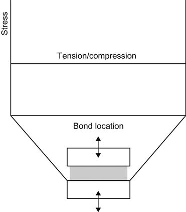
The stress distribution on the adhesive affects the ability of the joint to accommodate loads. Joint design should strive to distribute the stresses equally over the bond area in order to create uniform stress on the adhesive. Adhesive bonds subjected to tensile, compressive, or shear stress during loading experience a more uniform stress distribution than bonds exposed to cleavage and peel stress. Tensile and compressive stresses are evenly distributed throughout the bond area; stress is represented by a straight line in Figure 7.18. The compressive strength of most adhesive films is greater than their tensile strength; optimal joint design should maximize compression and minimize tensile stresses. The stress distribution of cleavage and peel stress is concentrated at one end of the joint (Figure 7.19). Peel strength of any adhesive may be as low as 1% of its shear strength; low-modulus elastic adhesives usually have higher peel strengths. Peel stress can be reduced through symmetrical joints, such as double lap. Joint design should ensure that peel and cleavage stress are minimized, and shear stress is maximized [14,15].
In shear stress, the ends of the bond resist a greater amount of stress than the middle of the bond (Figure 7.20). The maximum stress experienced by the ends of the joint is greater than the average stress (joint load divided by bond area); lower than average stress occurs in the middle of the joint. This stress distribution is due to the flexibility of plastic materials, which tend to bend when a load is applied, increasing stress concentrations at the joint ends. Stress ratios (highest stress/average stress) of plastics (15), with relatively low elastic moduli (2068 MPa unfilled plastic), are much greater than stress ratios for steel (1.7), with a high elastic modulus (212,000 MPa). Stress concentrations can lead to joint failure at relatively low loads; however, stress concentrations can be reduced by a joint design that takes into account the elastic modulus of the adhesive, the joint overlap length, and the bond line thickness [14,16].
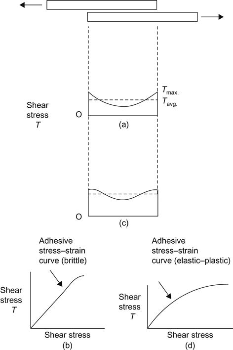
The elastic modulus of the adhesive influences the stress distribution of the joint. The shear stress distribution of a more brittle, higher modulus adhesive, with a stress–strain curve as shown in Figure 7.20(a), shows a linear increase in stress from the center to the ends of the joint (Figure 7.20(b)). A more elastic adhesive with a higher elongation and stress–strain behavior as shown in Figure 7.20(d) exhibits a nonlinear stress distribution (Figure 7.20(c)). The flexibility of the more elastic adhesive allows the joint to more readily accommodate motion of the adherends; stress is then distributed over a larger area, and the stress ratio (highest stress/average stress) is reduced. Substitution of a lower modulus (1.4 MPa) adhesive for a higher modulus (2068 MPa) adhesive can reduce the stress ratio from 22.4 to 1.2. Although a lower modulus adhesive may, for some applications, produce a stronger joint, it may not be able to accommodate structural loads without excessive deformation. Due to the greater area under the stress distribution curve, the more elastic adhesive experiences a higher average stress than a brittle adhesive of the same strength. For two adhesives of the same strength and elongation, the higher modulus, brittle adhesive would tolerate higher loads. Brittle adhesives, however, are more sensitive to crack propagation and generally have lower fatigue life than more elastic adhesives [14,16].
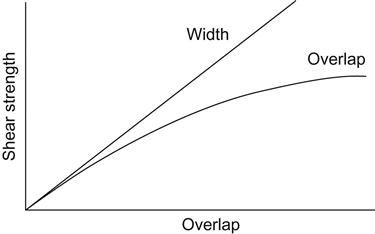
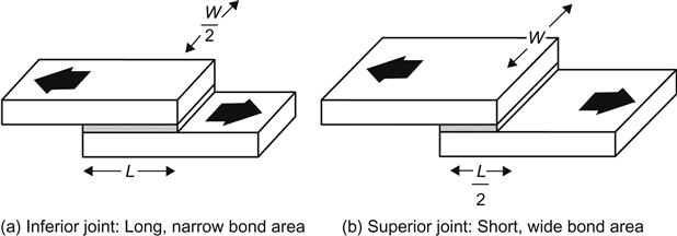
Although bonds with larger areas generally have higher strength, bond width is a more important design parameter than bond length or overlap. Bond strength increases slightly with overlap length (Figure 7.21) up to a point, and then remains constant. Due to the shear stress concentration at the ends of the joint, however, shear strength is directly proportional to bond width (Figure 7.21). A 2-cm-wide joint is twice as strong as a 1-cm (0.4 in)-wide bond, but a 2-cm-long joint is not twice as strong as a 1-cm joint. A short, wide bond area (Figure 7.22(b)) is stronger than a long, narrow bond area (Figure 7.22(a)). Bending and differential shear stress concentrations are reduced with shorter bond overlaps; decreases in overlap length from 2.54 to 0.32 cm can result in reduction of the stress ratio (highest stress/average stress) from 22.5 to 3.78 [14,16,17].
A thicker bond line can reduce shear stress concentration by spreading the strain over a larger dimension, resulting in less strain on the adhesive. An increase in bond line gap from 0.0025 to 0.10 cm can decrease the stress ratio from 18.2 to 3.06 [14,16].
The most common method for reducing stress concentration in lap joints is tapering the adherends, in a tapered lap joint (Figure 7.23(a)). Stress at the joint ends is reduced, allowing for a more uniform stress distribution. Modeling studies indicate that both adhesive peel and shear stresses decrease with a decrease in taper angle, with the optimum angle being the smallest angle that can be economically machined and assembled. A step lap joint (Figure 7.23(b)) can be used to avoid a large change in stress concentration from the ends of the joint to the center when long overlap lengths are necessary [14,16].
7.11.3 Failure Analyses
The function of a structural adhesive joint is to transmit an external load to the structural member. If the joint fails to function as it is intended, it will undergo damage or failure. The damage could be actual fracture of the structure, excessive elastic deformation, or excessive inelastic flow. The criteria for what constitutes structural failure depend on the performance requirements of the joint. The fundamental problem in the mechanics of adhesives and joints is to obtain some relationship between the loads applied to the joint and a parameter that will adequately describe the criteria for structural failure. The most common criterion for such failure of lap-type joints is actual fracture of the joint. For a given combination of adherend and adhesive, the stress analyst must decide what the mode or theory of failure would be if the applied loads become large enough to cause failure. The decision as to which theory would realistically determine the mode of failure is usually based on past experience, or upon some form of experimental evidence [12].
The next step is to determine a relationship between the applied load and a parameter that will describe the failure of the joint. Such parameters might be stress, strain, strain energy, etc. Finally, when maximum tolerable stresses have been obtained, the allowable stress values or factors of safety are decided upon to allow for factors such as long- and short-term loading, fatigue loading, special environmental conditions, and other special considerations. This step is ordinarily based on experience, engineering judgment, and legal, government, or commercial specifications [12].
7.11.4 Methods of Stress Analysis
Theory of Volkersen: In 1938, Volkersen analyzed the distribution of shearing stresses in the adhesive layers of a lap joint. Volkersen’s model is useful only with very stiff adhesives, which do not bend on loading the joint. A dimensionless stress concentration factor is found to depend on the geometry and the physical parameters of the joint. By introducing further simplifications, certain reasonable geometric conditions, and identical adherends, a simple formula is obtained [14]:
where G is the shear modulus of the adhesive, E is the Young’s modulus of the adherend, d is the thickness of the adherend, L is the length of the overlap, and t is the thickness of the adherend.
DeBruyne has suggested that, when all other variables are kept constant, the quantity √t/L with dimension (length)−1/2, the “joint factor” derived from the above equation, is useful in correlating joint strengths [14].
Volkersen’s theory predicts that the shear stresses in the adhesive layer reach a maximum at each end of the overlap, when the bonded plates are in pure tension. Photoelastic analyses of these composite structures show that stresses are uniform in the central part of the model adhesive, but high near the edges of the steel plate used in the analysis (Figure 7.3). Stress distributions at the end were found to be independent of the length of the overlap, when its length was at least three times the thickness of the adhesive layer [14].
Theory of Goland and Reissner: In Volkersen’s theory, the so-called tearing or peeling stresses were ignored. Goland and Reissner [16] took the bending deformation of the adherends into account, as well as the transverse strains in the adhesive and the associated tearing stresses. These researchers showed that the maximum tearing and shear stresses reach asymptotic values for large overlap lengths. Provided the system remains linearly elastic, the joint strength reaches a limiting value with increasing overlap length. In actual practice, however, a limiting strength is obtained because the adherends are loaded to their ultimate strength [15].
7.12 Optimizing Adhesive Bonding Through Joint Design—A Practical Approach
Adhesive joints are far less geometrically limited than mechanical fastener counterparts. This gives designers a great deal of flexibility to focus on the various mechanical and chemical stresses a specific joint is expected to withstand at its anticipated service temperature range. During the design phase, particular attention must be paid to the potential effects of mechanical shock and vibration, especially in dynamic bonding applications. Furthermore, assembly, manufacturing methodology, and cost factors must all be taken into account when proposing a joint design [18].
An understanding of the various possible joint designs for an application is an essential step to finding the optimum bonding solution. Typical joint design and stress development data offers designers a number of choices. Figure 7.24 shows the most widely in-use types of joint designs.
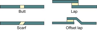
The butt joint is the simplest design. It is simply bonding two parts end to end. Generally, butt joints are not recommended for applications where available surface area is less than 12–25 mm, such as thin films, sheets, and fibers. Bonding strengths for properly designed butt joints can vary from 5.5 MPa in excess of 20.7 MPa.
Scarf joints are similar, but have the joints leveled at matching angles to increase the available surface area and the shear resistance. Shear stresses set in a plane with two substrates moving in opposite directions occur quite often. Most structural adhesives can withstand 13.8–20.7 MPa of shear stress at room temperature.
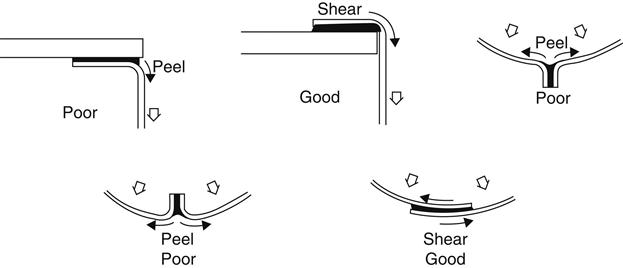
In a lap joint, two substrates are joined by bonding together large surfaces of each piece. Bonding the same substrates by using the butt or scarf joints would result in less surface area being joined than for a lap joint. While lap joints allow more bonding area, they can, however, result in offset surfaces being susceptible to peel, which occurs when one of the substrates is deformed and pulled away from the bond line of the other substrate (Figure 7.25). Less commonly used, cleavage stresses develop when tensile forces are unevenly applied to one edge of a joint, forcing it to open. Both cleavage and peel failures decrease the effective surface area of the bond and can initiate “unzipping” between the substrates as pressure continues to be applied to the joint [18].
When subjected to tensile stress, the two substrates pull away from each other perpendicularly to their surfaces. In contrast, compressive stresses occur when the substrates are forced toward each other. Structural adhesives typically have tensile strengths of 55.2 MPa to 82.8 MPa and compressive strengths of 69 MPa to more than 276 MPa.
It would be remiss not to emphasize the impact and importance surface preparation has with regard to bonding. Many adhesives fail to meet their full potential bond strength because of improperly prepared surfaces prior to adhesive application.