Chapter 4: Drawing with the Pencil, Paintbrush, Pen, and Shape Tools
Now, we are going to look at the variety of drawing and painting tools offered in Illustrator. There are a lot of options and approaches to each tool, so although this won't be a comprehensive list of everything you can do with each, I hope you find something helpful to add to your own bag of tricks after reading this chapter.
After completing this chapter, you should have expert knowledge of paths, anchors, strokes, and fills. You should also have a lot of additional knowledge on the use of direction lines and direction points for editing an object's path.
To accomplish this, the chapter will be divided into the following main topics:
- Making the Pencil tool work for you
- Loading and creating brush profiles
- Advanced training on the Pen tool and anchor point editing
- Exploring simple shape tools and the Shaper tool to develop more advanced objects
- The Pathfinder panel for heavy lifting
Technical requirements
To complete this chapter, you will need the following:
- Adobe Illustrator 2022 (version 26.0 or above).
- High-quality internet access may be required for some situations.
- Although not required, a quality graphics tablet or touch screen is recommended.
Making the Pencil tool work for you
To begin using the Pencil tool (N) (or any of the other tools we will be looking at in this chapter), we must first discuss what makes up all vector objects. All vector objects are made up of straight lines and/or curves. The curves are developed based on a mathematical formula. The benefit of this is that a vector path has smooth edges at any resolution, unlike a raster-based file, which is made up of a finite number of squares (also known as pixels) of color.
To that point, once you have selected the Pencil tool and its attributes, you will be able to draw freehand vector paths and closed vector shapes, as seen in the figure that follows:

Figure 4.1 – Artwork in Preview mode
In Figure 4.1, we see that the Preview mode allows you to see your creation with all its attributes applied to the vector paths. As we discussed in earlier chapters, attributes include options such as Stroke, Fill, and brush definitions. To see only the vector paths of the objects, choose the Outline mode – View > Outline or Ctrl/Command + Y.
The following figure shows how the art in Figure 4.1 appears after completing the Outline mode command:
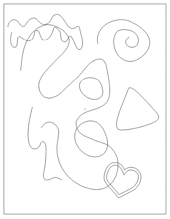
Figure 4.2 – Artwork in Outline mode
Viewing your artwork in Outline mode is an excellent way to focus on the quality of your shapes before enhancing them with attributes. The paths in Figure 4.2 were created using the Pencil tool in combination with the Smooth Tool.
Using the Pencil may be a bit difficult at first, but the following suggestions will make it much easier to get this tool to do your bidding:
- Draw slowly and freely to create organic shapes. If you need a straight line, hold down the Shift key as you draw.
- As you get close to the start of your path, a small circle will appear next to the pencil icon to let you know that you are about to close the object. Just hover over this symbol and let go to close the shape.
- If any part of your path was not drawn to your liking, just redraw that section by beginning this path adjustment on the previous path, as well as ending it by connecting back to a previous part of the original path.
- If it makes a new path instead of correcting the previous one, just undo (Ctrl/Command + Z) and try again. Be careful to start and end on the original path.
hen you have a path you are generally happy with, use the Smooth Tool to smooth the path and reduce the anchor points along it. The Smooth Tool can be found in the same tool group as the Pencil tool or can be summoned by holding Alt/Option while using the Pencil tool. The Pencil Tool Options panel must have the Option key toggles to Smooth Tool option checked for this to work (see Figure 4.3).
Creating with the Pencil tool will take some time to get used to, but it is the most natural drawing method within Illustrator. If you find it difficult to make a long stroke using this tool, you can draw one section of the path at a time. When placing the tool close to the end of the current path, you should see a diagonal line beside the icon for the tool. This indicates the ability to connect to the previous path. Click and draw to connect and continue to add complexity to your path. The Pencil Tool Options panel must have Edit selected paths checked for this to work (see Figure 4.3).
You can also customize Pencil Tool Options by double-clicking on the tool's icon in the toolbar. You can also adjust the Fidelity slider to change the path from being more accurate to being smoother:

Figure 4.3 – Pencil Tool Options panel
The following figure highlights the Pencil tool's ability to create fluid, hand-drawn paths and shapes quickly:

Figure 4.4 – Artwork created using the Pencil tool
The preceding artwork may initially have some odd forms, but these can easily be edited using the methods we have previously discussed in this section.
Drawing with the Pencil tool allows for a high level of flexibility in your work and can easily be edited using these redrawing and smoothing techniques. In Figure 4.4, you can view an early sketch of a sandwich in both Preview and Outline modes (use Ctrl/Command + Y to switch between them), while in Figure 4.5, you can see that both the top and bottom buns have been redrawn by adjusting their active paths with the Pencil tool and Smooth Tool:

Figure 4.5 – Artwork edited using the Pencil tool redraw technique
After creating the path, just remember to be sure that it has an active path before trying to redraw over a portion of it with the Pencil tool again. If it is no longer active, you will need to use the Selection tool (V) to make it the active selection, and then choose the Pencil tool to start somewhere on the path as well as end the adjustment at a different area of the old path. This should allow you to try multiple times (if needed) to get the path you desire.
In addition, remember that you may also choose the Smooth Tool to allow Illustrator to reduce and adjust the anchors creating your object for smoother curve transitions. You can either find the tool by clicking and holding over the Pencil tool icon (you will find it directly under the Pencil tool icon) or you can just hold down the Alt/Option key while using the Pencil tool. This will temporarily change the Pencil tool to the Smooth Tool and then return to the Pencil once it is released.
Practicing these two techniques will allow you to adjust any vector path with ease. It will work with any previously drawn vector shape or path, no matter what tool you used to create it.
Next, we will be looking at customizing paths with a variety of Paintbrush tool (B) options.
Loading and creating brush profiles
The Paintbrush tool allows for a large variety of options. We will first look at how you can find those that are already installed in Illustrator, and then we will discuss how to create new ones.
Loading brush profiles
The default brushes can get you accustomed to using the tool and offer you several options, but eventually, you are going to want more choices for brush options. Knowing where you can find extra installed brushes is a good place to start when expanding your choices for customization:
- Open the Brushes panel.
- Access the Brushes Library menu in the upper right or lower left of this panel and choose a library.
- In the new window, locate the desired brush profile.
In Figure 4.6, you can see what this should look like. When you locate the desired brush profile and click on it, it will be added to the document's current brushes. You should now see it as an option within the Brushes panel:
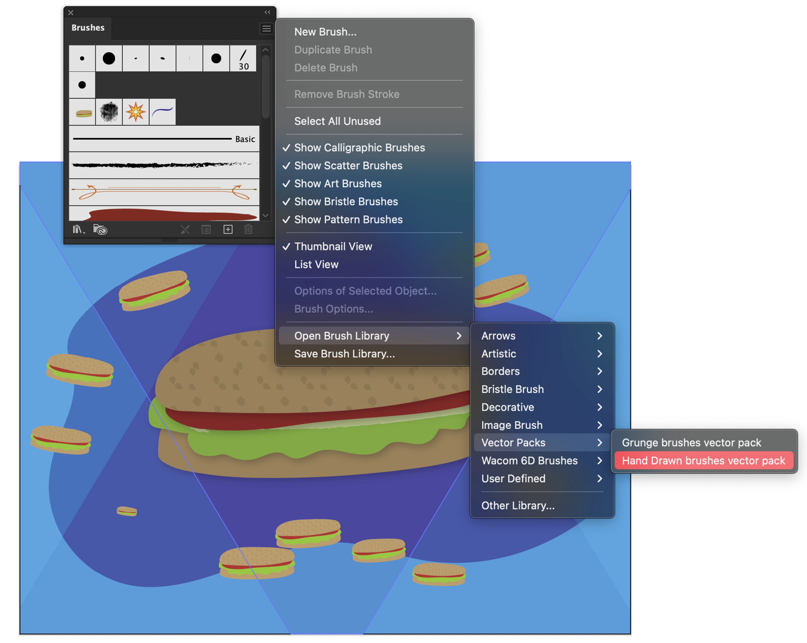
Figure 4.6 – Loading brush profiles from the Brushes panel
In addition to being able to load additional brushes, you can also adjust current brush profiles or build entirely new ones. Next, we will look at the options for brush profiles and how you can design your own custom profiles.
Creating brush profiles
There are five types of brush profiles in which you can create artistic strokes. These are Calligraphic Brush, Scatter Brush, Art Brush, Bristle Brush, and Pattern Brush.
The first of the five more traditional brush types we will look at is Calligraphic Brush. This is intended to create strokes that resemble marks made with the angled nib of a calligraphic pen. It uses a shape as a brush tip and routes it along a path, so a simple circle is used to create a non-calligraphic stroke, and changing the roundness and angle will result in a calligraphic stroke. In Figure 4.7, you can see the Calligraphic Brush Options panel. After opening the Brushes panel (Window > Brushes), double-clicking on a brush profile will bring up this options panel:

Figure 4.7 – Calligraphic Brush Options panel
The next brush to consider is Scatter Brush. It distributes copies of an image along a path. As you can see in Figure 4.8, you have several variable options with this style of brush. You can customize the brush's Size, Spacing, Scatter, and Rotation values. The seven options available for each of these variables are Fixed, Random, Pressure, Stylus Wheel, Tilt, Bearing, and Rotation:

Figure 4.8 – Scatter Brush Options panel
One of the most often used variations of Brush Tool is Art Brush. This brush allows you to scale a single brush stroke shape onto a path. The options panel, as seen in Figure 4.9, allows you to choose between three scaling options. It may be scaled proportionately, stretched to fit the stroke length, or stretched between two predetermined guides that you adjust. The width adjustment can be Fixed, or adjusted at Width Points, Pressure, Stylus Wheel, Tilt, Bearing, or Rotation:

Figure 4.9 – Art Brush Options panel
A beautiful and intuitive Paintbrush tool variation is Bristle Brush. It allows a wide variety of adjustments to customize the texture of your brush. You can adjust Size, Bristle Length, Bristle Density, Bristle Thickness, Paint Opacity, and Stiffness:

Figure 4.10 – Bristle Brush Options panel
The final brush profile is Pattern Brush. This is similar to Calligraphic Brush as it repeats a brush tip, but it also allows for alternate patterns for the inside and outside corners. It can also have unique start and end patterns for open strokes:

Figure 4.11 – Pattern Brush Options panel
Now that we have reviewed all the varied brush profile choices, you should be able to make a more informed choice as to which one you are using to make your custom brush. Use the following steps to create your own brushes:
- Create a shape or path that you would like to use as the basis for the brush.
- Open the Brushes panel.
- Access the New Brush command in the upper right or lower right (the + icon) of this panel.
- Choose the brush profile method you would like to use.
Calligraphic Brush is an exception to this, as you do not have to create a vector shape or path beforehand. Just select the New Brush command and adjust the brush tip in the options panel that is presented during this process.
Blob Brush tool
In addition to the traditional Paintbrush tool, there is also Blob Brush (Shift + B).
Blob Brush is unique as it does not paint a path, but rather, it makes a vector path around the perimeter of the fill of the brushstroke(s). As you continue to paint, the vector path continues to surround the ever-growing "blob" that you paint. If you are painting with the same color, each additional brush stroke will continue to grow the selection:

Figure 4.12 – Blob Brush use
Using the Pencil and Paintbrush tools will allow you to create hand-crafted objects freely and intuitively, but they may not offer you the control and accuracy that you need for a particular task. Next, we will look at the distinct advantages of both creating with the Pen tool and editing at very specific points along any path.
Advanced training on the Pen tool and anchor point editing
So far, we have been focused on creating paths with tools that follow the movement of your mouse, a gesture on the touchpad, or a swipe of a pencil on a tablet.
The Pen tool gives additional control by placing anchor points and direction handles along the path, which you can use to adjust it. The following steps can be used as an introduction if you are somewhat new to this tool:
- Select Pen tool (P).
- Drop an initial anchor point by clicking anywhere on the artboard.
- Move the tool, and then click again to create a straight line.
- Hold Shift while clicking to constrain the straight line to a multiple of 45˚.
- Click and drag the Pen tool to create the direction handles of the anchor point.
- click and drag again to choose the angle and scale of the curve segment, and then release.
As noted in steps 3 and 4, holding down the Shift key while drawing allows you to draw straight lines at controlled angles:

Figure 4.13 – Holding Shift to constrain lines to vertical, horizontal, or 45˚ angles
As noted in steps 5 and 6, you can choose the desired angle and depth of curves using the direction handles:
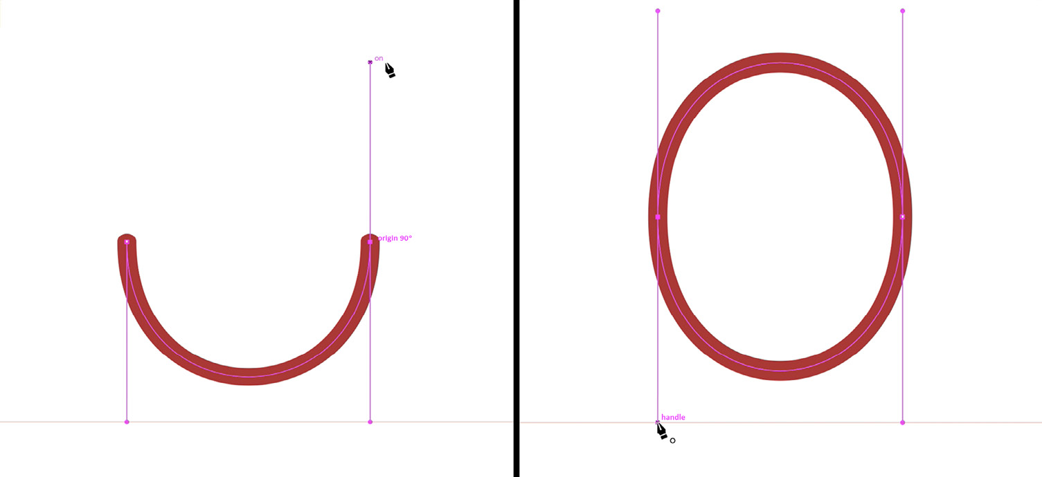
Figure 4.14 – Drawing out directional lines to create angle and depth of curves
In addition to the traditional Pen tool, there is also the Curvature tool (Shift + ~), which allows you to draw with a more intuitive approach. Follow these steps if you would also like an introduction to this tool:
- Select the Curvature tool.
- Drop an initial anchor point by clicking anywhere on the artboard.
- Move the tool and then click again to create a straight line.
- As you move away from the second anchor, a suggested path appears,which allows you to make a better choice as to where the next anchor should be placed for your intended shape.
- As you continue to drop anchors, the suggested path continues to appear and give you suggestions as to the placement of each additional anchor.
- Any time you would rather that the anchor creates a corner, just hold Alt/Option while placing it.
- When editing, anchors can also be converted from corner to curve or vice versa by clicking on them while holding Alt/Option.
- You can also edit a shape while you are still on the Curvature tool. Just click on any single anchor, and then drag it to its new location.
- While you are still using the Curvature tool, you can also add additional anchors by clicking on the path.
- You can also convert any of the anchors by simply double-clicking them while still using the Curvature tool.
Of all the vector drawing tools within Illustrator, I found the Curvature tool was the most difficult to get used to and understand its true benefits. As you continue to use it, the tool's true potential will start to come out. The Curvature tool gives you the ability to create smooth curves very quickly through a method of previewing them before committing to them, as shown in this figure:
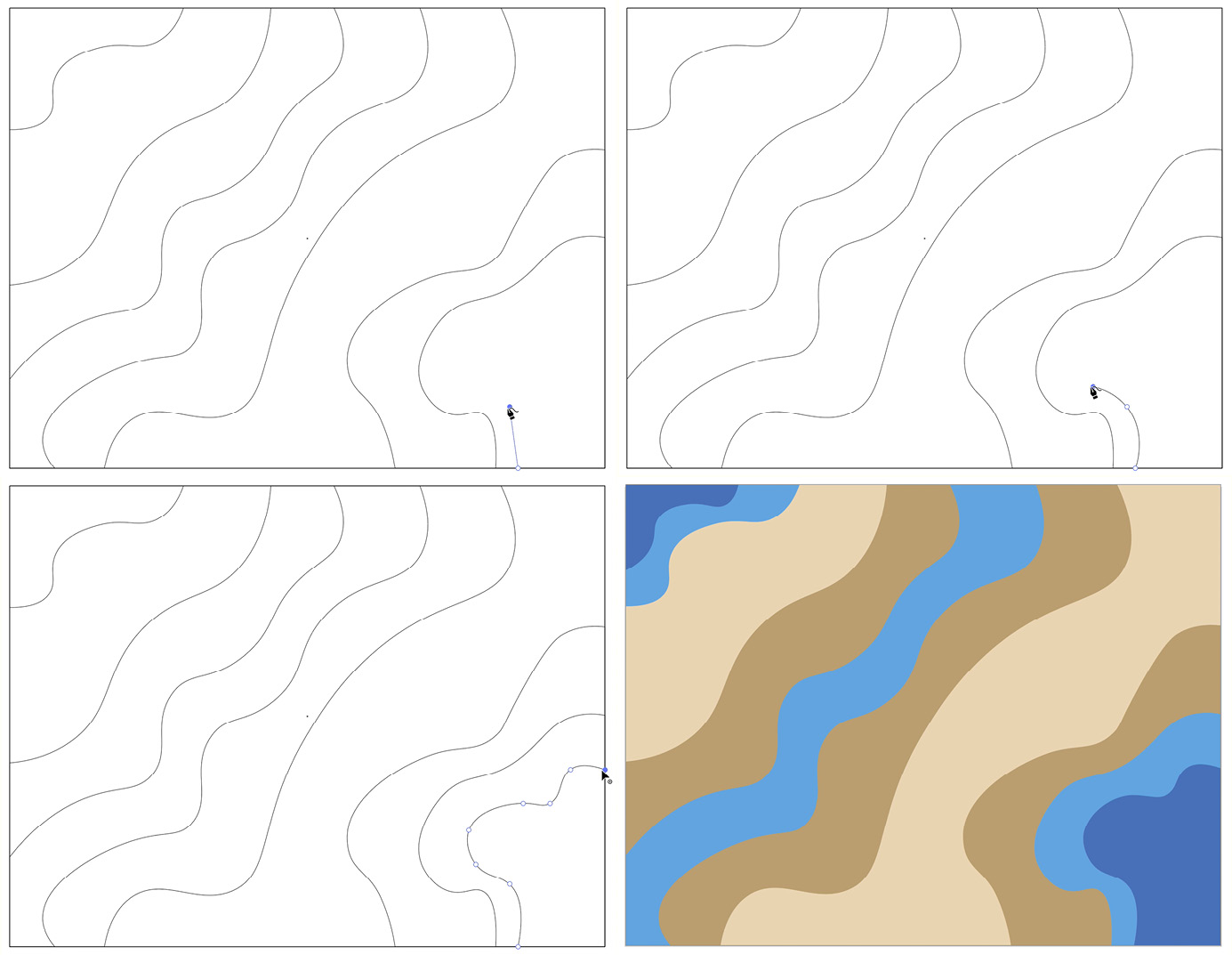
Figure 4.15 – Curvature rool (top left), adding a second anchor (top right), suggested curves as anchors are added (bottom left), and converting corner anchors by Alt-clicking (bottom right). Suggested curves are applied after the final anchor is placed
With the ability to preview the path as it is being developed, you might find there isn't as much need to edit the path after it's been created, but you can still select individual anchors or add additional anchors to the path using the Curvature tool. You can also use Direct Select Tool to select several anchors at once by holding the Shift key while clicking on them. This will be discussed in greater detail in the next subsections, but an example of an adjustment can be seen in Figure 4.16:

Figure 4.16 – The Curvature tool aids in creating smooth curves
Figure 4.16 shows the adjustment from Figure 4.15, which was created, in part, from the ability to select and edit the anchors of the previously drawn shapes.
The variety of tools that Illustrator offers allows you to create very accurate artwork using methods most appropriate for your specific situation. Having this variety of tools often gets you very close to what you intended, but knowing exactly how to control and manipulate the vector paths down to the anchor level will allow you to master your designs.
Advanced training on the Pen tool
The Pen tool is not the easiest tool to get used to, but with these tips, and some practice, you should be able to see its advantages soon. Generally, the Pen tool allows you to create either straight path segments or curved path segments, and any combination of the two. The following list will allow you to create open and closed paths with great accuracy:
- Select the Pen tool.
- Drop an initial anchor point by clicking anywhere on the artboard.
- Move the tool and then click again to create a straight segment.
- Move the tool to a new location and click again to create the next straight segment.
- If a curved segment is required along the path, just click and drag to create direction handles for the anchor.
- The angle and length at which you pull the handles will impact the curve's size and direction.
- To continue the curve, move the tool in the desired direction and click to drop a new anchor.
- If you want to convert the last anchor from corner to curve or vice versa, just hold Alt/Option and click on it.
- If you want to split the direction of an anchor, just hold Alt/Option and click and pull on one of the direction handles.
As noted in step 6, you can choose the desired angle and depth of curves using the direction handles. Think of a direction handle as a tool that works to bend and stretch this thin band of wire:

Figure 4.17 – Adjusting curves with direction handles
After becoming more familiar with the Pen tool, you will start to get better at deciding what to do to make the intended shape, but even if it all goes well, the shape usually requires some editing. You may consider doing what you've learned and switching to the Direct Select Tool (A) to edit the path at the individual anchor level. You can most certainly do that, but you should also be aware that it can be done while you are still using the Pen or Curvature tools. Let's look at that next.
Advanced training on anchor point editing
As I just mentioned, as you get more comfortable with the Direct Select Tool and the techniques for editing individual anchors, you should try using keyboard shortcuts to become more efficient with your editing. With keyboard shortcuts, you should be able to edit your anchors as you continue to draw your vector path. I would suggest trying the following shortcuts to speed up your workflow:
- Hover over the last anchor to convert it from corner to curve or vice versa.
- Hold the Alt/Option key while clicking and moving the curve anchor handle to create curves on both sides of a corner anchor.
- Hold Ctrl/Command to change your cursor to the Direct Select Tool. This will allow you to quickly move between selecting the entire shape or just a specific anchor.
- The Delete/Backspace key will remove the last anchor point.
Give those shortcuts a try and you might find less and less need for switching continually between the Pen and Direct Select tools.
Now that we covered most of the drawing tools within Illustrator, I think it's time to talk about the times when you need to create work with very accurate shapes. The shape tools and Shaper tool, along with some advanced modification tools (such as the Shape Builder tool and the Pathfinder panel) will allow you to create very precise artwork.
Exploring simple shape tools and the Shaper tool to develop more advanced objects
I personally love creating in Illustrator using the simple shapes that the shape tools offer. Let's first look at the simplest drawing methods and then examine some methods for adding and subtracting from combined objects.
Shape tools
As we look at the list of available shape tools, please be aware that the Flare tool is also in this same family of tools. We will not be discussing it with the others, as it has a very different purpose and often feels like it should be located with some other tool family. If you are unfamiliar with the tool, it is used to create a simulated lens flare and can be fun to use, but this just isn't the right time to examine it. Instead, we will be sticking to the five main shape tools:
- Rectangle Tool (M)
- Rounded Rectangle Tool
- Ellipse Tool (L)
- Polygon Tool
- Star Tool
To select any of these tools you can use their keyboard shortcuts, click and hold on the top tool in the tool family within the toolbar, and then select your choice from the visible icons or use the shape tools tear-off panel. To engage this option, just hold your mouse button down while in the tool family view, move your cursor to the right so it is hovering over the small arrow, and then let go of the mouse button. A new panel of all the shape tools will now be floating in your workspace. If you ever want to close it, just click on the X button at the top left of the panel, as shown here:

Figure 4.18 – Engaging the Shape Tools Tear-Off panel
You may also use keyboard shortcuts while drawing with these tools to gain additional benefits. Holding the Shift key while drawing with the Rectangle Tool (M) will create a perfect square. Similarly, holding the Shift key when using the Ellipse Tool (L) to create a perfect circle. If you hold the Shift key while using either the Polygon Tool or Star Tool, it will align the object to be level in relation to the base of the document.
The Rectangle Tool, Rounded Rectangle Tool, and Ellipse Tool draw outward from the point of origin (where you began the shape) and continue to grow in the direction you draw to. If you hold the Alt/Option key while drawing with these tools, center as the point of origin from which the shape is drawn outward.
Shift and Alt/Option modifier keys may be used together to combine their benefits. For example, holding down both of these modifier keys while drawing with the Rectangle Tool will result in a perfect square being drawn outward from the point of origin.
If you are drawing with either the Polygon Tool or Star Tool, you can adjust the number of sides/points by tapping the up and down arrows of the keyboard while holding the left mouse button down. You will gain more sides/points each time you tap the up arrow, and less each time you tap the down arrow.
Instead of drawing with your mouse, you can also create any of these shapes by clicking on the artboard after selecting the chosen shape. This will bring up the options panel for the chosen shape. This will give the Constrain Width and Height Proportions link for rectangles, rounded rectangles, and ellipses so that you can either make perfect shapes or scale shapes to a common ratio. With the link icon selected, each time you change one of the two dimensions, the other grows or shrinks at the same ratio. In the case of Figure 4.19, the rectangles were created using a consistent 1:2 ratio. The first was a 5 by 10 pt rectangle and then the width was increased by 5 each time. To maintain the ratio, Illustrator changed the height by 10 each time, as shown here:

Figure 4.19 – The Constrain Width and Height Proportions link creating a series of shapes
When drawing a polygon or star, clicking on the artboard will again bring up the options panel for them, but will allow for the number of sides/points and the shape's radius. In the case of a star, Radius 1 is the outer radius, and Radius 2 is the inner radius:

Figure 4.20 – Inner and outer radius using Star Tool's options panel
If you are drawing with the Rounded Rectangle Tool, you can use the keyboard's directional arrows to adjust the radius of the corners. While holding down the up arrow, you will slowly increase the radius of the rectangle, and holding down the down arrow will slowly decrease the radius. Tapping the right arrow will result in a maximum radius while tapping on the left arrow will result in a minimum (no) radius. I use the left and right keys to get closer to the radius and then apply either the up or down key to move from either the maximum or minimum radius. Keep in mind that these shortcuts will only work while continuing to hold down the mouse button. After releasing the mouse button, you can still adjust the radius of all the corners by using the Selection tool to select the shape and then click on and move one of the Live Corner widgets. If you would like to adjust one or more (but not all) of the corners, use the Direct Selection tool – click on any corner anchor, hold Shift while selecting the second and/or third corner anchor, and then click on and move any of the Live Corner widgets.
In addition to the shape tools, Illustrator also offers several unique tools that focus on lines instead of shapes. The Line Segment tool () allows you to click and drag with the left mouse button held to draw a straight-line segment at any angle. In addition, if you hold the Shift key while drawing out the line, it can travel horizontally, vertically, or at a 45˚ angle, depending on the direction your mouse travels. Holding down the Alt/Option key, in this case, will allow the line segment to grow outward evenly from the point of origin.
Just like the previous shape tools, you can also select The Line Segment tool and then click on the artboard to bring up the options panel. The Length and Angle values in the options panel will always match the previous line segment drawn, so it is an excellent way to place duplicate line segments right where you want them. Just click the desired location, and hit Enter/Return to accept the dimension and angle:

Figure 4.21 – Using the Line Segment tool Options panel
Within the same family of tools is the Arc tool. This tool allows you to make custom, smooth arcs. With some adjustments in the tool's options panel, you can also make closed shapes that can be filled or unfilled. Clicking anywhere on the artboard while using the tool will present you with the options panel. See Figure 4.22 for the Type choices that Arc tool offers you, as well as Length X-Axis and Length Y-Axis, Slope, and Base Along X-Axis or Y-Axis:

Figure 4.22 – Using the Arc Segment Tool Options panel to create an arc, an unfilled shape, and a filled shape
In addition to simply drawing out arcs with this tool or using the tool's options panel, by clicking on the artboard or double-clicking on the tool's icon in the toolbar, you can also adjust the tool by utilizing the same familiar keyboard shortcuts you might use for other drawing tools. If you hold Shift, it will constrain to a 45˚ angle between the two anchors making up the arc. Holding Ctrl/Command will allow you to draw the arc outward from the point of origin. Tapping or holding the up arrow will increase the slope while tapping or holding the down arrow will decrease the slope. Remember that this will only work while you continue to hold down the mouse button.
In addition to all these techniques for path tools and the adjustment of the paths they draw, the one that is by far the most unique is the tilde (~) key; although it has limited usage, I believe you will find it interesting if you are not yet familiar with its results. The benefits of the tilde (~) key will be discussed in Chapter 5, Editing and Transforming Objects.
Shaper tool
The Shaper tool (Shift + N) will attempt to understand your gestures. If you draw a path with a circular shape, a perfect circle magically appears. This will also work for ovals, triangles, squares, rectangles, and hexagons:
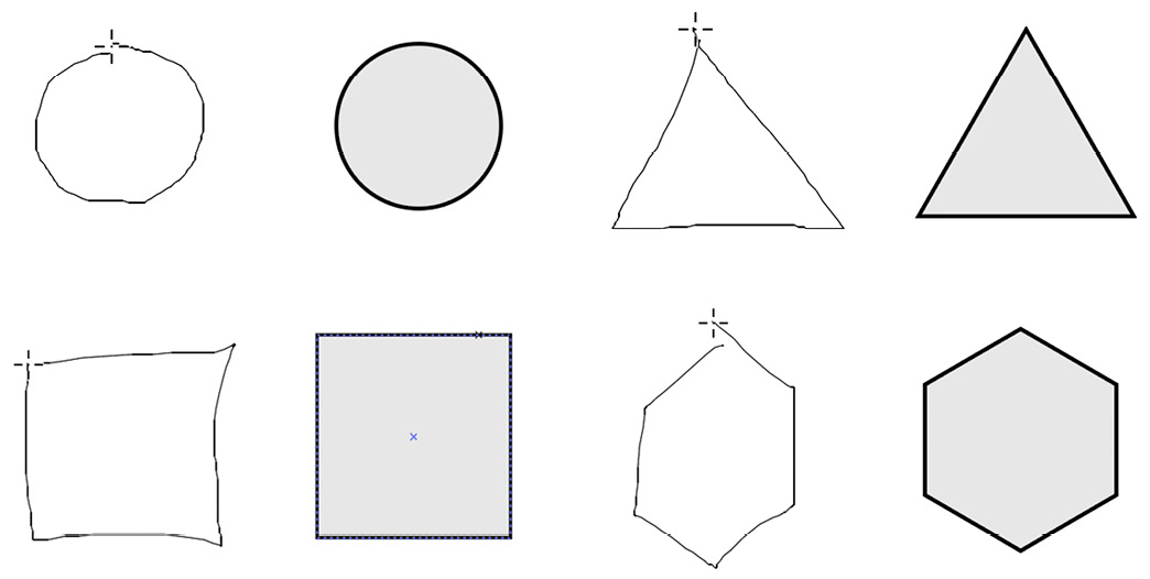
Figure 4.23 – Shaper tool converts a free-hand gesture into a circle, ellipse, rectangle, triangle, or another polygon
This tool also allows you to use free-hand gestures to create additional shape constructions. Be sure to start with a collection of overlapping shapes, which can be created using the Shaper tool or any other drawing tool. Then, select the Shaper tool and scribble within a shape or overlapping area to subtract the area (any group of overlapping shapes will automatically be put into a Shaper Group and highlighted while using the Shaper tool). For example, I have scribbled over the overlapping area of the red rounded rectangle and the green circle in Figure 4.24. This figure shows the resulting area being punched out of the Shaper Group:

Figure 4.24 – Subtraction of overlap using a gesture
In addition to using a mouse gesture to create this scribble, if available, you can also use either a stylus and a tablet or a touch screen to complete the gesture.
In Figure 4.25, applying a scribble gesture over the area of the blue triangle not overlapping the green circle has resulted in the removal of the non-overlapped portion of the triangle:

Figure 4.25 – Subtraction outside overlap using a gesture
If you were to make a similar gesture on the portion of the rounded red rectangle that was not overlapping the green circle, the same action would result, and the green color would remain on the overlapped area.
You can also merge shapes using this method of scribble gestures. As you can see in Figure 4.26, I have scribbled across all the shapes to merge them into one. The merged Shaper Group will be colored with the color of the shape at the point of origin of the gesture. In this case, it is red, as I began on the red rounded rectangle and ended on the blue triangle, as shown here:
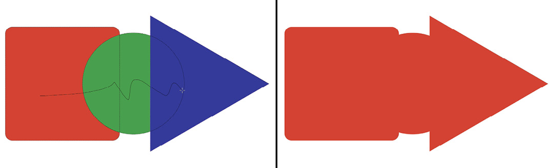
Figure 4.26 – Addition of overlap using gesture
If you are starting with a shape behind the others, then scribble from the non-overlapped area to the overlapped area to merge them. If you are trying to merge to the top shape, then start on the overlapped area and scribble back to the underlying shape. This will allow you to retain the top shape's color upon merging the two.
After using the Shaper tool in this way, it will assign these shapes to a Shaper Group and allow them to remain interactive. To interact with any of these new groups, select the Shaper tool and then select one of these groups. It will become selected and display an arrow widget. If the arrow is pointing down, it indicates that you can select the entire group. Clicking the objects in the group will make it active and it can then be edited as one object or can continue to be edited with the scribble gestures. The top two screenshots in Figure 4.27 illustrate how the group looks after being selected:

Figure 4.27 – Editing a Shaper Group using the arrow widget
The bottom two screenshots in Figure 4.27 illustrate that you can also engage any specific shape that originally made up this now merged object. To do this, you will need to click the arrow widget and it will then change to an arrow pointing upward. Now, you can click on any individual shape and make the desired adjustments. In the case of Figure 4.27,I adjusted the radius of the triangular portion of the Shaper Group.
Next, let's look at a tool that can be used very similarly, but that requires you to simply draw a line, or at times, requires just a simple click of the mouse.
Combining shapes with the Shape Builder tool
If you aren't familiar with this technique, I am confident that you will find it useful and quite enjoyable to do. It has many similarities to the Shaper tool, but I find it simpler and more intuitive, as it not only allows you to combine and remove areas by using overlapping shapes, but it also considers every overlapping area as a potential new shape. For example, you could join two overlapping areas without joining the original shape. Just like the Shaper tool, it can be used with overlapping shapes that were created with any of the drawing tools:
- Select all objects you intend to use with the Shape Builder tool.
- Select the Shape Builder tool (Shift + M).
- Draw through the shapes you would like to unite. They will join to create a new shape.
- Hold down the Alt/Option key and click or draw through shapes you would like to remove. They will be subtracted from the rest of the selection.
- Hold down the Shift key in addition to the Alt/Option key while drawing through the shapes to allow them to be selected within a selection rectangle. Also, you can hold Shift + Alt/Option to subtract within a selection rectangle.
Figure 4.28 illustrates that drawing a long meandering line (left) can result in several shapes being merged into one (right):

Figure 4.28 – Drawing through multiple shapes to unite
I especially like this technique for constructing shapes, but remember to try out each method and consider how they each have their benefits and drawbacks. It really depends on the use case. There are times when these techniques are not enough and you need something with more options. That's where the next tool comes in.
The Pathfinder panel for heavy lifting
If the situation does not allow for simple addition or subtraction of combined elements, then it might be time to use the advanced properties of Pathfinder. Pathfinder was in Illustrator long before the Shape Builder tool, but I would now recommend the Shape Builder tool as a primary option and Pathfinder as a secondary option when needed. It allows for more unique options for blending multiple objects.
As Figure 4.29 shows, the Pathfinder panel is divided into two areas: Shape Modes and Pathfinders:

Figure 4.29 – The Pathfinder panel
To illustrate this tool, we will use a sample image made up of several shapes and show the results of each method. This artwork will be used to run through all Shape Modes and Pathfinders, and then I will share the results from the two categories:

Figure 4.30 – Original
Figure 4.31 shows the results after applying each of the shape modes:

Figure 4.31 – Shape Modes
The original, as you can see in Figure 4.30, is made up of two grouped sets of shapes, so it results in an appearance you would expect each time. In Figure 4.31, this is how each of the shape modes works:
- UNITE puts both parts together and uses the attributes of the top object.
- MINUS FRONT removes the overlapping area that was taken up by the top group of shapes.
- INTERSECT results in the areas that both groups have in common.
- EXCLUDE results in the shapes that are different in both groups.
Figure 4.32 shows the results after applying each of the Pathfinders:
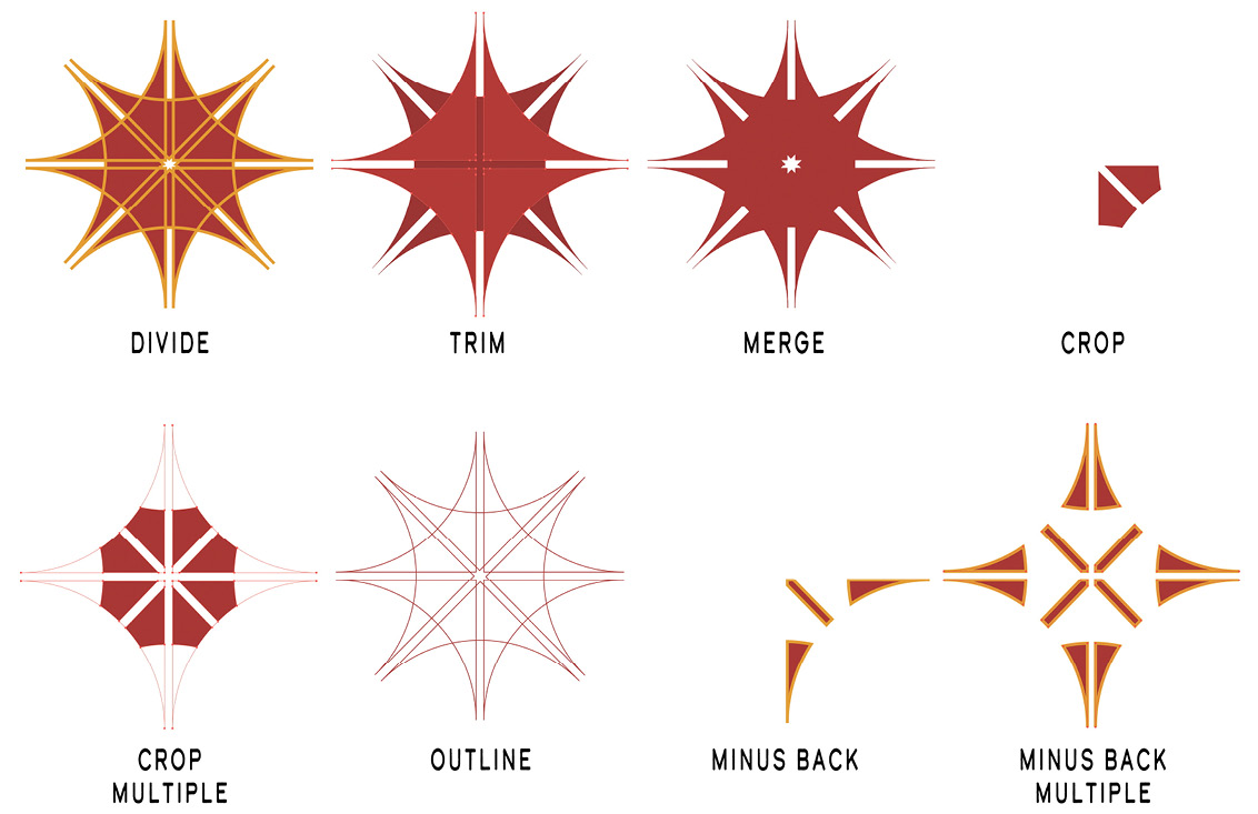
Figure 4.32 – Pathfinder modes
Let's discuss each of the Pathfinders in Figure 4.32:
- DIVIDE splits all the enclosed vector paths into individual objects.
(To edit the newly created objects, you will need to ungroup the result.)
- TRIM removes any strokes but doesn't merge fills.
- MERGE removes any strokes, as well as merges any of the same colors that are overlapping.
- CROP removes any strokes and then deletes all but the top-most object (note that multiple copies of the original shapes were used to create the CROP MULTIPLE result).
- OUTLINE divides the objects into their line segments (useful for creating a trap for overprinting).
- MINUS BACK removes the overlapping area that was taken up by the bottom group of shapes (again, note that multiple copies of the original shapes were used to create the MINUS BACK MULTIPLE result).
We have now examined several methods to draw, edit, and combine objects. Next, let's look at a method that allows for even greater flexibility for later editing when combining objects.
Compound paths
Compound paths are when two or more paths are combined so that holes appear where paths overlap. You can create this by selecting both objects that have a common overlap, right-clicking, and choosing Make Compound Path from the contextual menu. You can also choose to go to Object > Compound Path > Make (Ctrl/Command + 8) from the menu bar to create the compound path. All objects in the compound path will take on the attributes of the backmost object in the stacking order.
As you can see in the demonstration of the sun image in Figure 4.33, the holes created from a compound path allow you to show underlying objects:

Figure 4.33 – (L to R) Compound path, simple path, and compound path over simple path
An additional benefit to this method is the ability to individually edit the members of the compound path.
Compound shapes
This last example shows the benefits of the compound shape. It allows you to hold multiple shapes together as one new shape but has the benefit of allowing further editing of the individual components within the compound shape. You can create a compound shape by holding down the Alt/Option key while selecting any of the shape modes in the Pathfinder tool. See Figure 4.34 for a detailed example:

Figure 4.34 – Top (L to R) – Multiple shapes, compound shape, and compound shape expanded; Bottom – Adjusted compound shape after being expanded
Double-click any individual shape within a compound shape to enter Isolation Mode and edit it individually. When you have completed the edit, you will need to click out of Isolation Mode by clicking the left-pointing arrow in the Isolation Mode bar (see Figure 4.33):
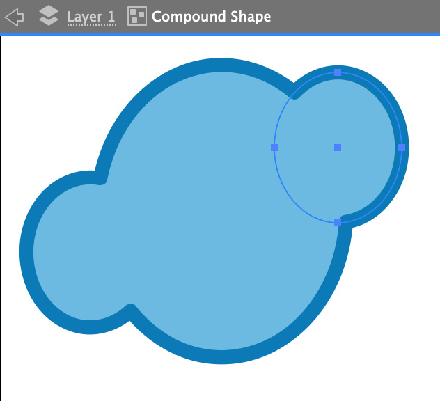
Figure 4.35 – Compound shape being edited in Isolation Mode
You might note that a difference between a compound path and a compound shape is that the latter will not create a hole with any of the objects included in the newly joined creation.
Summary
After having completed this chapter, you now know how to use a variety of drawing tools that come with Adobe Illustrator. You also now know how to build more complex illustrations using these tools individually or in combination.
We have reviewed the attributes of each tool and several techniques for utilizing them to a high level of their capabilities.
All the information within this chapter was intended to challenge you to venture out with your creativity and find new ways to transfer it to the artboard using this variety of tools to deliver your concepts.
In the next chapter, we will be discussing several techniques for editing and transforming your newly drawn objects. You will learn that you have complete control of the shape and form of your vectors and can reshape their paths at any time. We will also explore some of the clever additional methods of manipulating their paths, through options and effects.