
Chapter 9. The Camera and Optics

A film is never really good unless the camera is an eye in the head of a poet.
–Orson Welles
It seems as if visual effects is all about simulating the look of the real world, but that’s not quite the goal; as a visual effects compositor, your actual job is to simulate the real world as it appears through the lens of a camera. The distinction is critical, because when photographed the world looks different—more or less real, and possibly both.
It’s not too grandiose to say that cinematography is essential to compositing, because After Effects offers the opportunity to re-create and even change essential shooting decisions long after the crew has struck the set and called it a wrap. Your shot may be perfectly realistic on its own merits but it will only belong in the story if it works cinematically. Factors in After Effects that contribute to good cinematography include
• Field of view
• Depth of focus
• The shooting medium and what it tells about the storyteller
• Planar perspective and dimensionality
• Camera motion (handheld, stabilized or locked) and what it implies about point of view
These seemingly disparate points all involve understanding how the camera sees the world and how film and video record what the camera sees. All of them transcend mere aesthetics, influencing how the viewer perceives the story itself.
Cameras: Virtual and Real
We begin our exploration of virtual cinematography with the After Effects camera, which relates closely to an actual motion picture camera without actually being anything like one. Following is an examination of how 3D operates in After Effects and how the application’s features—not only the camera, but also lights and shading options—correspond to real world counterparts.
See with the Camera
Toggle a layer to 3D and voila, its properties contain three axes instead of two—but enabling 3D without a camera is a little bit like racing a car with automatic transmission: You can’t really maneuver, and before long you’re bound to slam into something.
The Camera Settings dialog (Figure 9.1) uniquely includes a physical diagram that helps tell you what you need to know about how settings in the 3D camera affect your scene.
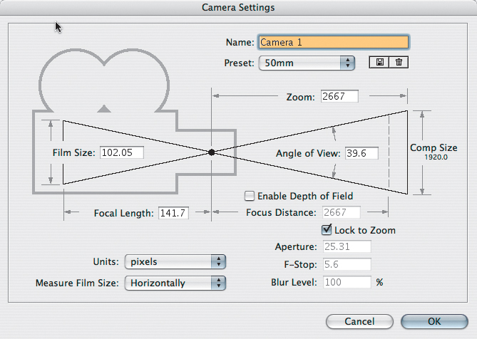
Figure 9.1. Artists love a visual UI, and the Camera Settings dialog provides one to help elucidate settings that might otherwise seem a bit abstract. The 50 mm preset is the neutral (default) setting.
Lens Settings
Although it is not labeled as such, and although After Effects displays previous camera settings by default, the true default lens preset in Camera Settings is 50 mm. This setting (Figure 9.2, see next page) is neither wide (as with lower values, Figure 9.3, see next page) nor long (as with higher values, Figure 9.4, see next page); and it introduces no shift in perspective.

Figure 9.2. The default lens (50 mm setting). If the Z Position value is the exact inverse of the Zoom value, and all other settings are at the default, this is the view you get, and it matches the appearance of setting no After Effects camera whatsoever.

Figure 9.3. The extreme wide or fisheye lens pointed inside an evenly proportioned 3D box. Note that the “long” look of the box is created by this “wide” lens, which tends to create very strange proportions at this extreme. A physical lens with anything like this angle would include extremely distorted lens curvature.

Figure 9.4. A telephoto lens (using the 200 mm setting) pushes items together in depth space, shortening the distance between the front and back of the box dramatically.
“50 mm” is a virtually meaningless term because virtual space doesn’t contain millimeters any more than it contains kilograms, parsecs, or bunny rabbits. This is the median lens length of a 35 mm SLR camera, the standard professional still image camera.
Motion picture cameras are not so standardized. The equivalent lens on a 35 mm film camera shooting Academy ratio itself has a 35 mm length. A miniDV camera, on the other hand, has a tiny neutral lens length of around 4 mm. The length corresponds directly to the size of the backplate or video pickup, the area where the image is projected inside the camera.
Lens length, then, is a somewhat arbitrary and made-up value in the virtual world of After Effects. The corresponding setting that applies universally is Angle of View, which can be calculated whether images were shot in IMAX or HDV or created in a 3D animation package.
Real Camera Settings
To understand the relationship of the After Effects camera to those of a real-world camera, look again at the Camera Settings diagram (Figure 9.1). Four numerical fields—Film Size, Focal Length, Zoom, and Angle of View—surround a common hypotenuse.
A prime (or fixed) lens would have static values for all four. A zoom lens would of course work with a fixed Film Size, but would allow Zoom and Focal Length to be adjusted, changing the Angle of View. These four settings, then, are interrelated and interdependent, as the diagram implies, and the relationship is just the same as with a real camera, which the Film Size can even help emulate. Lengthen the lens by increasing Focal Length and you decrease Angle of View.
The settings you actually use are Zoom (to animate) and Angle of View (to match real-world source).
A fifth numerical field in Camera Settings, Focus Distance, is enabled by checking Enable Depth of Field; it corresponds to a camera’s aperture setting, covered here separately.
Angle of View is the actual radius, in degrees, that fit in the view. If you’re matching it, note that Camera Settings lets you specify a horizontal, vertical, or diagonal measurement in the Measure Film Size pulldown.
In After Effects, the Zoom value is the distance of the camera, in pixels, from the plane of focus. Create a camera and its Z Position is the inverse of the Zoom value, perfectly framing the contents of the comp with a Z position of 0.0 (Figure 9.5). This makes for easy reference when measuring depth of field effects, and it allows you to link camera position and zoom together via expressions (for depth of field and multi-plane effects, discussed later).

Figure 9.5. Comp Size (at the right) is the horizontal size, in pixels (although it always appears vertical in the diagram); orientation changes according to the Measure Film Size settings (left). Instead of pixels, you can measure in inches or millimeters, helpful when matching a physical camera (process described ahead).
Emulate a Real Camera
Other considerations when matching a real-world camera include
• Depth of field: This is among the most filmic and evocative additions you can make to a scene. It doesn’t exist by default in After Effects the way it does with real-world optics, so you have to re-create it.
• Zoom or push: A move in or out is used for dramatic effect, but which type is it?
• Motion blur and shutter angle: These are composition (not camera) settings; introduced in Chapter 2, “The Timeline,” they are further explored here.
• Lens angle: The perspective and parallax of layers in 3D space change according to the angle of the lens used to view them.
• Lens distortion: Real lenses introduce lens distortion, curvature most apparent with wide-angle or “fisheye” lenses. An After Effects camera has no lens, hence, no distortion, but you can re-create it (see “Lens Distortion”).
• Exposure: Every viewer in After Effects now includes an Exposure control (look for the aperture icon, lower right); this (along with the effect with the same name) is mathematically similar but practically different from a physical camera. Usage of these tools is detailed in Chapter 11, “32 Bit HDR Compositing and Color Management.”
• Boke, halation, flares: All sorts of interesting phenomena are generated by light interacting with the lens itself. These are subjective and almost abstract in reality, yet I think they offer a unique and beautiful aesthetic if grounded in realism.
The movement of the camera itself can generate motion blur (Figures 9.6a and b). The key is that any layers to be blurred by the motion of the camera have Motion Blur toggled on.

Figures 9.6a and b. Camera movement generates motion blur (a); even on a stationary layer provided motion blur is active for the comp and layer (b). New in CS3, zooming the camera can also generate motion blur.
A camera report is a record of the settings used when the footage was taken, usually logged by the camera assistant (or equivalent).
The Camera Report
With accurate information on the type of camera and the focal length of a shot, you know enough to match the lens of that camera with your After Effects camera.
A potentially easier alternative to the listed steps, for those who like using expressions, is to use the following expression on the camera’s Zoom property:
FocalLength = 35 // change to your value, in mm
hFilmPlane = 24.892 //change to your film size, in mm (horizontal measurement)
this_comp.width*(Focal Length/hFilmPlane)
Table 9.1 details the sizes of some typical film formats. If your camera is on the list, and you know the focal length, use these to match the camera via Camera Settings. The steps are
1. Set Measure Film Size to Horizontally. (Note that hFilmPlane below stands for “Horizontal Film Plane.”)
2. Set Units to Inches.
3. Enter the number from the Horizontal column of the chart that corresponds to the source film format.
4. Set Units to Millimeters.
5. Enter the desired Focal Length.
Table 9.1. Typical Film Format Sizes
Courtesy Stu Maschwitz/The Orphanage

Once the Angle of View matches the footage, any objects that you track in (perhaps using techniques described in Chapter 8, “Effective Motion Tracking”) maintain position in the scene as the shot progresses. It’s vital to get this right when the camera moves during the shot, and especially if a wide or long lens was used.
Included on the book’s disc is a 12 minute video tutorial (courtesy fxphd.com) in which Mike Seymour shows how information including viewing angle and focus distance can be derived even if these were not recorded when the image was shot.
Lens Distortion
If a virtual camera is set with a wide-angle lens, as in Figure 9.2, it dramatically changes the perspective of 3D space, but it does not actually distort objects the way a real camera lens does because a digital camera uses no lens. A virtual camera can widen the view area and still scan it in a linear fashion, because all the imagery travels to a single point.
A lens curves light to project it properly across the camera backplate with physical width and height, no matter how small. To show up properly the reflected imagery must be perpendicular to the surface of the lens glass, so a wide-angle view requires not only a short lens length but also a convex lens in order to gather the full range of view.
At the extremes, this causes easily visible lens distortion; items in the scene known to contain straight lines don’t appear straight at all, but bent in a curve (Figure 9.7). In a fisheye lens shot, it’s as if the screen has been inflated like a balloon.
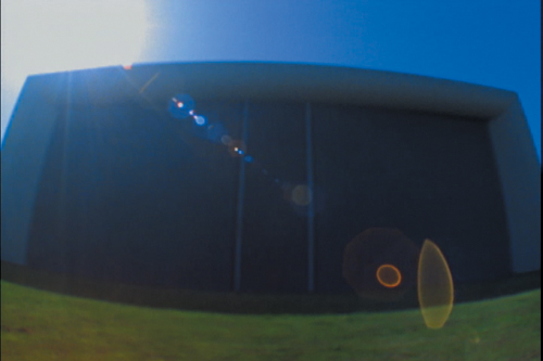
Figure 9.7. The almost psychedelic look of lens distortion at its most extreme; the lens flare itself is extremely aberrated. You can create just as wide a lens with the 3D camera, but there would be no lens distortion because there is no lens.
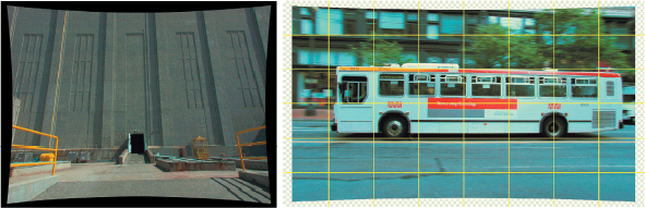
As you refine your eye, you may notice that many shots that aren’t as extreme as a fisheye perspective contain a degree of lens distortion. Or you might find that motion tracks that are accurate on one side of the frame don’t seem to apply equally well at the other side of the frame, proportions go out of whack, and things don’t quite line up as they should (Figures 9.8a and b).

Figures 9.8a and b. It is simply not possible to make all four corners and edges of a yellow solid line up properly with the side of a distorted building (a). Grid lines over footage of the bus clearly show distortion (b). (Building examples courtesy Stu Maschwitz; bus footage courtesy Pixel Corps.)
There’s no way to introduce lens distortion directly to a 3D camera, but the Optics Compensation effect (Professional version only) is designed to add or remove it in 2D. Figures 9.9a and b shows this effect in action. Increasing the Field of View makes the affected layer more fish-eyed in appearance; to correct a shot coming in with lens distortion, check Reverse Lens Distortion and raise the Field of View (FOV) value.
Figures 9.9a and b. Optics compensation takes place in a composition larger than the source; the padding gives the corners of the image space. The Beam effect can serve as a virtual plumb line (a) or it can be clear from the grid that distortion has been corrected (b).
This process is not exactly scientific, instead requiring eye-match because the Field of View settings don’t correspond to measurable items in the camera report, such as the Lens Angle. Specifically
1. Having identified lens distortion in a background plate (as in Figure 9.8a), precomp the background into a new composition that is at least 20% larger than the plate to accommodate distortion.
2. Add an adjustment layer above the plate layer, and apply Optics Compensation to that layer. Check Reverse Lens Distortion and raise the Field of View (FOV) setting until all straight lines appear straight.
3. Add a Beam effect to the adjustment layer (below the Optics Compensation effect, unaffected by it). To get away from the light saber look, match Inside Color and Outside Color to some easily visible hue, then align the Starting Point and Ending Point along an apparently straight line near the edge of frame. Fine-tune the Field of View setting a little more until the line is plumb (Figures 9.9a and b).
4. Precompose all of these layers and set this new composition as a guide layer. In Figure 9.10, you can see that the corner pin is now successful.

Figure 9.10. Over the undistorted background plate, you can freely position, animate, and composite elements as if everything were normal. Note that the perspective is still that of a very wide-angle lens, but without the curvature.
5. To complete the shot, restore the original field of view, including distortion. First create a new comp with the original background plate (no Optics Compensation) and the precomp with the assembled foreground elements.
6. Copy Optics Compensation with the settings added in step 2 and paste it to the foreground element. Toggle Reverse Lens Distortion off. The Field of View of the background is restored, but the foreground elements match (Figure 9.11).
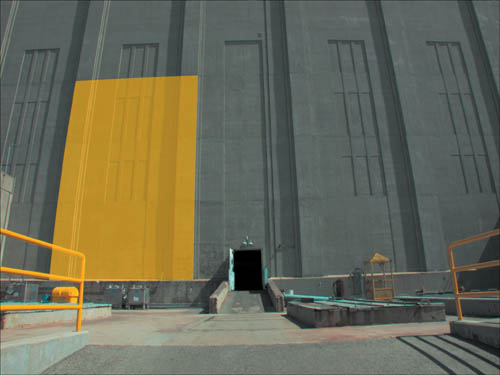
Figure 9.11. The Optics Compensation effect with Reverse Lens Distortion unchecked adds the original distortion to the foreground; features now line up properly.
Here is an original haiku (Stu Maschwitz gets the writing credit) to sum up the process:
undistort, derive
reunite distorted things
with an untouched plate
2D and 3D
The point of matching 3D lens angles (and correcting any distortion) is most often to place elements in 3D space over a 2D plate background. This is so effortlessly possible in After Effects as to seem like no big deal:
• A 2D background layer remains in place (usually simply filling the frame) no matter how you move the camera.
• 2D adjustment layers set to comp size and default position affect the whole composition, including 3D layers.
• 3D layers can use vital features unique to 2D compositing, such as blending modes (over 2D elements, they obey layer order, and with other 3D elements, z-space depth).
Here are special cases that require extra care:
• It’s rarely a good idea to combine a 3D track matte and a 3D layer. A 3D layer can use a 2D layer as a track matte; it is applied just as it would be to a 2D layer. A 2D layer can use a 3D layer as a track matte; the 3D perspective of the track matte renders first and is then applied. But combine two 3D layers in this manner and the matte is first translated by the camera perspective once, then applied, and then effectively translated again as the affected layer also obeys camera perspective.
• Paradoxically, the only layers in After Effects that themselves can contain true 3D data are 2D layers (which may nonetheless make use of the 3D camera perspective, Figure 9.12).

Figure 9.12. Incredibly, particles generated by Trapcode Particular occupy true 3D space, as is evident in a perspective view. Paradoxically, the effect is applied to a 2D layer. It calculates 3D data internally using the After Effects camera as a reference, an elegant workaround for the fact that 3D layers in After Effects are always flat planes.
• A precomped set of 3D layers behaves like a single 2D layer unless Collapse Transformations is enabled on that layer. As described back in Chapter 4, “Optimize the Pipeline,” this toggle passes through all 3D data from the precomp as if those layers lived right in the master composition.
Every one of these has potential advantages provided you understand how the image pipeline works.
Storytelling and the Camera
Locked-off shots have been used to great dramatic effect in landmark films by Welles, Hitchcock, Kubrick, and Lucas, among others, but they’re the exception, not the norm, particularly in contemporary films, in which the camera point of view often can itself be a character.
Always keep in mind where the audience’s attention is focused—you can employ the magician’s technique, misdirection, to get away with something you shouldn’t. As is detailed in the fun book Rebel Without a Crew (Plume, 1996), El Mariachi got completed with meager funds only because Robert Rodriguez was willing to let massive continuity errors go. He was confident that if the audience was watching for those, the story had failed.
In the bad old days of optical compositing, it was scarcely possible to move the camera at all. Nowadays, most directors aren’t satisfied with a locked-off effects shot, yet the decision to move the camera might not happen on set, or it might have to be altered in post-production. This is no big deal; you can bend the rules, just don’t break them.
Specifically, create a rough assemble with animation as early in the process of creating your shot as possible, because it will tell you a lot about what you can get away with and what needs dedicated attention. The “Sky Replacement” section in Chapter 13, “Climate and the Environment,” contains an example in which a flat card stands in for a fully dimensional skyline (Figure 9.13). The audience should instead be focused on watching the lead character walk through the lobby, wondering what he has in his briefcase; if not, the film has more problems than can be fixed with more elaborate visual effects elements.

(Image courtesy The Orphanage.)
Figure 9.13. Prominent though it may appear in this still image, the audience isn’t focused on that San Francisco skyline outside the window. There’s no multiplaning as the camera moves because the background skyline is a still image; no one notices because viewer attention is on the foreground character.
Camera Animation
The most common confusion about the After Effects camera stems from the fact that by default, it includes a point of interest, a point in 3D space at which the camera always points, for auto-orientation. The point of interest is fully optional, yet the setting is among the least discoverable in After Effects. To clarify
• Disable auto-orientation and the point of interest (making the camera a free camera) by context-clicking on the camera and choosing Transform > Auto-Orient (Ctrl+Alt+O/Cmd+Option+O) (Figure 9.14).

Figure 9.14. So many After Effects 3D camera tragedies could have been avoided if more users knew about this dialog box (Ctrl+Alt+O/Cmd+Option+O). By disabling auto-orientation, you are free to move the camera anywhere without changing its direction.
• In that same dialog, you can instead orient the camera along its path of camera motion, so that its rotation maintains tangency; in other words, it is angled the same direction as the path itself.
• You might want to use the point of interest but also move it and the camera together. To do this, don’t attempt to match keyframes for the two properties—this is sheer madness! You can parent the camera to a null and translate that instead.
• Orientation works differently depending on whether auto-orientation is on (causing it to revolve around the point of interest) or not (in which case it rotates around its center, Figure 9.15).

Figure 9.15. Just in case you’ve never taken a close look, a camera layer contains no anchor point, but includes two sets of rotation data: the Orientation (its basic angle), as well as separate X, Y, and Z Rotation values (to avoid problems with complex 3D rotations). The point of interest appears only when the default Orient Towards Point of Interest option is active (Figure 9.14).
• The auto-oriented camera always maintains an upright position; cross over the X/Y plane above the center and the camera flips. To avoid this behavior, use a free camera.
The above points come into play only with more elaborate camera animations; more modest use of the 3D camera, such as a simple camera push, raises other questions.
Push and Zoom
A camera push moves the camera closer to the subject; a zoom lengthens the lens while the camera remains stationary. Figures 9.16a and b demonstrate the difference, which is just as noticeable in After Effects as in the real world. The zoom has a more extreme effect on the foreground/background composition of the shot—often too extreme, calling too much attention to the camera itself.

Figures 9.16a and b. Frame a similar shot with a long (a) and a wide (b) lens and you get an idea of the difference between a zoom and a push. A zoom merges the relative scale of objects at various depths, lowering apparent perspective.
Cycle through the camera animation tools using the C key to orbit, track X/Y, and track Z in the active view.
The Y axis is upside down in After Effects 3D, just as in 2D; increasing the Y value moves a layer downward. The 0,0 point in After Effects space was placed at the upper-left corner of the frame when it was 2D only, and so it remains for consistency’s sake.
Dramatic zooms for the most part had their heyday in 1960’s-era Sergio Leone movies, while the push is a dramatic staple. The question is, to create one do you need a 3D camera, or can you simply scale 2D layers?
Scaling a 2D layer (or several parented to a null) works for a small move; however, to re-create progression through Z space the rate of scaling must increase logarithmically, which makes everything more complicated. Not only does a 3D camera move provide this type of scaling naturally, it makes it easier to add eases, stops and starts, a little bit of destabilization—whatever works.
The zoom may merely be out of fashion and ready to make a comeback, but it calls attention to the camera because the human vision system has no equivalent; our eyes can only push as we progress through space—they can’t zoom.
Natural camera motion will contain keyframe eases (Chapter 2), for the human aspect. A little bit of irregularity lends the feeling of a camera operator’s individual personality (Figure 9.17), or even dramatic interest (hesitation, caution, intrigue, a leap forward—the possibilities are many).

Figure 9.17. A simple camera animation can be finessed simply by applying Easy Ease (highlight keyframes and press F9), but why stop there? Lengthening the curve of the first keyframe gives the camera added (realistic) inertia transitioning from a static position.
Animation > Keyframe Assistant > Exponential Scale is the old-school, pre-3D way to fake the illusion of a camera move in on a 2D layer. There is no good reason to employ this feature when you can instead animate a 3D camera.
A move in or out of a completely 2D shot can easily look wrong due to the lack of parallax. Likewise, tracking and panning shots, crane-ups, and other more elaborate camera moves will blow the 2.5D gag unless minute. You can, however, get away with more layering soft, translucent organic shapes, such as clouds, fog, smoke, and the like. Chapter 13 shows how, by staggering these in 3D space, you can fool the eye into seeing 3D volume.
When pushing in on multiple overlapping coplanar 3D layers, precompose before adding the camera animation and leave Collapse Transformations off. Coplanar 3D layers respect layer order, but an animated camera can easily cause rounding errors in floating point position calculation.
Camera Projection
Camera projection (or camera mapping) typically begins with a still photo, which is then projected onto 3D objects that match the dimensions and placement of objects in the photo, and then moving the camera—typically only along the Z axis—providing the illusion that the photo is fully dimensional (right up until the camera move goes too far, revealing some area of the image that wasn’t part of the photograph).
Figures 9.18a, b, and c show a camera projection that ambitiously features two parked military vehicles in the foreground. A dozen separate white solids with masks were created to form a crude 3D model, ready to receive a projected image (Figure 9.19). This example shows both the magic of this technique—deriving perspective shifts from a flat, still image—and the associated problems of image tearing when an area of the frame is revealed that had previously been obscured in the source photo.

Figures 9.18a, b, and c. The progression from the source image (a) through the camera move. By the final frame (c), image warping and tearing are evident, but the perspective of the image is essentially correct for the new camera position. The tearing occurs simply because as the camera moves it reveals areas of the image that don’t exist in the source.
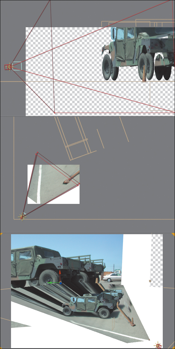
Figure 9.19. The rather complicated setup for this effect: from the top and side views you can see the planes that stand in for the vehicles and orange cone, which appears stretched along the ground plane.
The key to this effect is the setup: How is it that the one “texture” of the image (the photo) sticks to the 3D objects? The fundamental concept is actually relatively simple; getting it right is a question of managing details, and that part is fairly advanced and not for the faint of heart (which is why mention of a third-party option follows this description). The steps to projecting any still image into 3D space (an example of which, 09_cameraProjection.aep, can be found on this book’s disc) are as follows:
1. Begin with an image that can be modeled as a series of planes.
2. Create a white solid for each dimensional plane in the image. Enable 3D for each, and under Material Options, change the Accepts Lights option to Off.
3. Add a camera named Projection Cam; if you know the Angle of View of your source image, add that value.
4. Add a Point light called Projector Light. Set its position to that of Projection Cam, then parent it to Projection Cam. Set Casts Shadows to On.
5. Duplicate the source image, naming this layer Slide. Enable 3D, and in Material Options, change Casts Shadows to Only and Light Transmission to 100%.
6. Slide not located properly? Add a null object called Slide Repo; set its position to that of Projection Cam, and parent it to Projection Cam. Now parent Slide to it, and adjust its scale downward until the image is cast onto the white planes, as if projected.
7. Now comes the painful part: masking, scaling, and repositioning those white solids to build the model, ground plane, and horizon onto which the slide is projected. Toggle on the reference layer and build your model to match that, checking it with the slide every so often.
8. If planes that you know to be at perpendicular 90 degree angles don’t line up, you need to adjust the Zoom value of the Projection Cam, scaling the model and slide as needed to match the new Zoom value. The example file includes an expression applied to the Scale value of the Slide layer so that the slide scales up or down to match however you adjust the Zoom of the camera, which is not necessary but is helpful.
9. Once everything is lined up, duplicate Projection Cam, and rename the duplicate (the one on the higher layer) Anim Cam. Freely move this camera to take advantage of the new dimensional reality of the scene (Figure 9.20).

Figure 9.20. Better than relying only on projection, which can lead to the tearing seen in Figure 9.18, is to position specific foreground layers. Here all of the people in the street are actually matted layers positioned in 3D space.
The best way to learn about this is probably to study the example file included on this book’s disc; if it seems enticing rather than aggravating, feel free to give it a whirl.
Camera Blur
Camera blur is the result of objects positioned outside the camera’s depth of field, whether because the lens was intentionally defocused or simply because the focal range was too shallow to capture everything sharply.
Buena Software offers a set of plug-ins known as Depth Cue, which includes Camera Mapper, a plug-in that controls this process and makes it easy to clean up such tearing and stretching errors as those seen in Figure 9.18c.
Ironically, the high-end medium of film naturally has a shallower depth of field than any video camera, and even more ironically, shallow depth of field and the aesthetic of camera blur is what you would call “cinematic” and thus largely desirable. A shallow focal range literally focuses the viewer’s attention; moving areas of a shot in and out of focus, meanwhile, can create dramatic anticipation and a beautiful aesthetic.
It can be a lot of work to re-create depth of field effects in After Effects; it’s better to get them in camera if possible. Nonetheless you can create specific cinematic blur effects such as a rack focus shot, in which the focus changes from a subject at one distance from the camera to another.
Limited focal range is a natural part of human vision, but camera lenses contribute their own unique blur characteristics that in the contemporary era are often considered aesthetically pleasing the world over. There is even a Japanese term (literally meaning “fuzzy”) to describe the quality of out-of-focus light as viewed through a lens, boke (also bokeh, more phonetic but clunkier).
You can create these effects and more in After Effects. It’s not automatic the way it is with the camera lens itself, and it can require patience and careful observation of nature, but if you’re a compositor you have those already.
Image Planes and Rack Focus
Any time you can divide a shot into distinct planes of depth with each plane as its own layer, you can rack focus. All you need is a focal point to animate and a depth of field narrow enough to create blur everywhere but the immediate plane of focus.
Narrow depth of field is created on a real camera by lowering the f-stop value, which lowers exposure as well. Not so with the After Effects 3D camera. Its Aperture and F-Stop settings (Figure 9.21) affect only focal depth, not exposure or motion blur. The two settings have an inverse relationship. F-Stop is the setting more commonly referenced by camera operators, and yet only Aperture appears as a property in the Timeline.
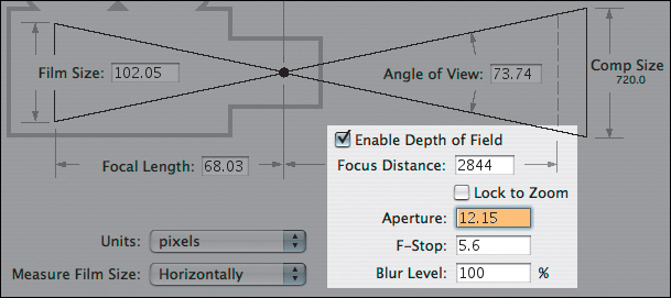
Figure 9.21. Check Enable Depth of Field in Camera Settings to activate Focus Distance (the distance in pixels of the focal point, which can be toggled to Lock to the Zoom). A low F-Stop (or high Aperture) with a Blur Level of 100% creates a shallow focal effect.
After Effects depth of field settings can be matched to a camera report, provided that it includes the f-stop setting used when the footage was shot. If so, open up the Camera Settings dialog (Ctrl+Shift+Y/Cmd+Shift+Y, or double-click on the Camera in the Timeline panel), check the box labeled Enable Depth of Field, and enter the value.
The key here is to offset at least one layer in Z space so that it falls out of focal range. Now, in the Top view, set the Focus Distance (under Options) to match the layer that will be in focus at the beginning of the shot, add a keyframe, then change the Focus Distance at another frame to match a second layer later in the shot (Figure 9.22).

Figure 9.22. With Enable Depth of Field on, the Focus Distance is denoted by a red boundary line, easily viewed and animated in isometric views.
A static focus pull doesn’t look quite right; changing focus on a real camera will change the framing of the shot slightly. To sell the example shot, which starts on a view of the city and racks focus to reveal a sign in the foreground, I add a slight camera pull-back, which takes advantage of the nice shift in planes of motion from the offset layers (Figure 9.23).
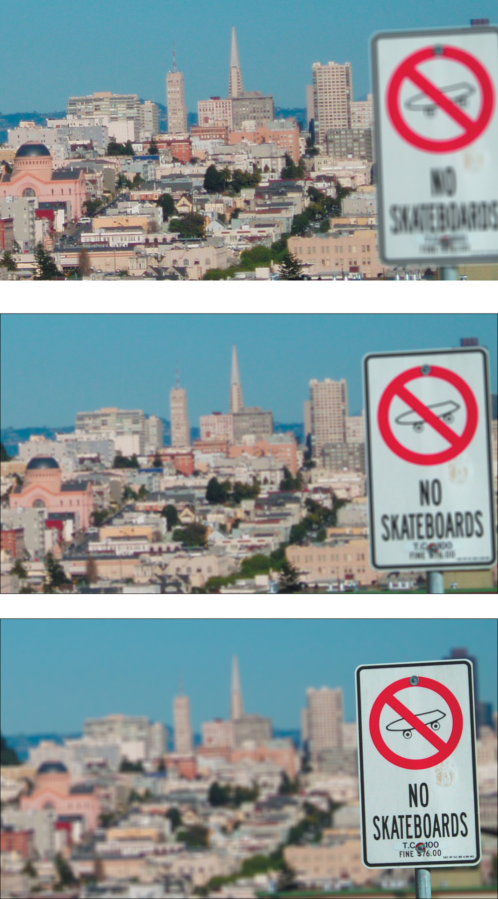
Figure 9.23. The final shot combines a rack focus with a gentle pull-back, using ease keyframes to animate Position and Focus Distance.
Boke Blur
Racking focus in this manner generates camera blur that is accurate relative to the plane of focus, but it does not truly create the look of a defocused lens.
Boke connotes the phenomenon whereby points of light become discs of light (also called circles of confusion) that take on the character of the lens itself as they pass through the camera lens and aperture. Like lens flares (covered in Chapter 12) these are purely a phenomenon of the camera lens, not human vision; they can add beauty and suspense to a shot.
Illuminated out of focus elements in a shot are, after all, mysterious. Visual intrigue is created as the shot resolves in or out of a wash of color and light (Figure 9.24).

Figure 9.24. Even in the very first, most blurred frame of this pull-back shot, you may recognize the image content, yet its appearance is strange and compelling. With shallow depth of field, highlights in the foreground retain blur even in a focused shot.
A perfect lens passes a defocused point of light to the back of the camera as a soft, spherical blur. A bright point remains bright, but is larger and softer. Ordinary blur in 8 or 16 bit per channel color mode instead merely dims the highlights (Figures 9.25a, b, and c).

Figures 9.25a, b, and c. Motion blur generated the standard way (a and b) literally pales in comparison to true motion blur on illuminated elements created by a moving camera (or objects) while the shutter is open (c).
Most camera lenses are not perfect, so instead of perfect blurred spheres, boke spheres may be brighter toward the edges than in the middle. An anamorphic lens will show squashed spheres, and as with lens flares, the shape of the aperture itself may be visible in the circles, making them hexagonal (or pentagonal, and so on, depending on the number of blades in the opening).
Go for Boke
To accurately create the bloom of highlights as they are blurred requires 32 bit per channel color and source highlights that are brighter than what would be called full white in 8 or 16 bpc. This is explored and explained in Chapter 11.
The Lens Blur effect does not operate in 32 bpc—it instead mimics the behavior of bright highlights through a lens. It’s more or less a direct port from Photoshop; as such, it can be slow and cumbersome in After Effects. It won’t blur beyond 100 pixels, and it does not understand non-square pixels (instead creating a perfect circle every time).
Instead of 3D camera or layer data, Lens Blur can use a Depth Map Layer, using pixel values (brightness) from a specified Depth Map Channel. You can rack focus by adjusting Blur Focal Distance. Iris Shape defines polygons around the highlights, corresponding to the number of blades in the iris; these can also have a specified Iris Blade Curvature and Iris Rotation (this rotates the polygon).
The most respected third-party tool for lens blurs is Frischluft’s Lenscare. The default settings are not reliable, but with adjustments and depth maps (for 3D footage), you can derive some lovely results (www.frischluft.com and on the book’s DVD).
The actual amount of blur is determined by Iris Radius, the bloom by Specular Threshold (all pixels above this value are highlights) and Specular Brightness, which creates the simulation of highlight bloom. These are the controls you’ll tweak most (Figure 9.26).
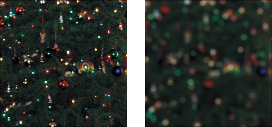
Figure 9.26. Lens Blur doesn’t yield a perfect result when cranked up this high, but it does generate the disk shapes around specular highlights characteristic of Boke blur (here, set as hexagons). The result on the larger specular area of the lamp is odd (due to a low threshold of 90%), and there is no repeat edge pixel option, leading to a translucent fringe.
The Noise controls are designed to restore noise that would be removed by the blur operation; they don’t relate to the blur itself and can be ignored in favor of grain techniques described in the following section.
By no means do the settings in Lens Blur (or for that matter, third-party alternatives such as Lenscare from Frischluft) exhaust the possibilities for how defocused areas of an image might appear, especially when illuminated. Keep looking at reference and thinking of ways to re-create what you see in it (Figure 9.27).
Figure 9.27. Now that you know a little more about the phenonemon of boke and how defocused images look, study up. Does an image with shallow depth of field look more cinematic? What do you see happening in the defocused background?
The Role of Grain
Once the image passes through the lens and is recorded, it takes on another characteristic: grain. Grain is essentially high-frequency noise readily apparent in each channel of most recorded footage, although with progress in image gathering technology has come a reduction of grain. Grain can however be your friend, adding life to static imagery and camouflaging edge detail.
Grain management is an essential part of creating high-quality moving images; properly done, it is not simply switched on or off, but requires careful per-channel adjustment. There are two basic factors to consider:
• Size of the grain, per channel
• Amount of grain, or amount of contrast in the grain, per channel
The day may come when digital cameras can deliver moving footage with no grain whatsoever. Already, all-digital movies that use no footage, such as those by Pixar, also do not use grain in the master.
The emphasis here is that these factors typically vary from channel to channel. Blue is almost universally the channel likeliest to have the most noise; happily the human eye is less sensitive to blue than red or green, but it can be bad news for blue-screen mattes.
How much grain is enough? As with color in Chapter 5, “Color Correction,” the goal is typically to match what’s there already. If your shot has a background plate with the proper amount of grain in it, match foreground elements to that. A fully computer-generated scene might have to be matched to surrounding shots.
Excessive grain is often triggered by a low amount of scene light combined with a low-quality image-gathering medium, such as miniDV, whose CCD has poor light-gathering abilities.
Grain Management Strategies
After Effects Professional includes a suite of three tools for automated grain sampling, grain reduction, and grain generation: Add Grain, Match Grain, and Remove Grain. Add Grain relies on your settings only, but Match Grain and Remove Grain can generate initial settings by sampling a source layer for grain patterns.
I often caution against the automated solution, but not in this case. Match Grain is not even appreciably slower with grain sampling than Add Grain, which does not sample but includes all of the same controls. Match Grain usually comes up with a good first pass at settings. In either case
1. Look for a section of your source footage with a solid color area that stays in place for 10 to 20 frames. Most clips satisfy these criteria, and those that don’t tend to allow less precision anyhow.
2. Zoom to 200% to 400% on the solid color area, and create a Region of Interest around it. Set the Work Area to the 10 or 20 frames with little or no motion.
3. Add a solid small enough to occupy part of the Region of Interest. Apply a Ramp effect to the solid, and use the eyedropper tools to select the darkest and lightest pixels in the solid color area of the clip. The lack of grain detail in the foreground gradient should be clearly apparent (Figure 9.28).
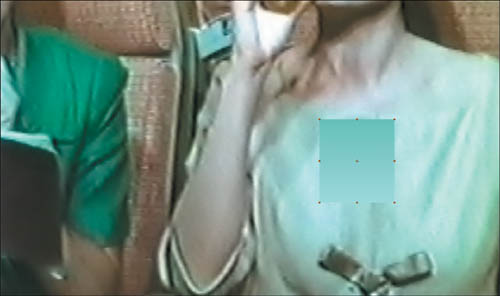
Figure 9.28. Insert a small solid and add a Ramp effect, then use the eyedropper tools in Ramp to sample the brightest and darkest areas of the background. This offers a clear evaluation of a grain match once Match Grain or Add Grain is applied.
4. Apply the Match Grain effect to the foreground solid. Choose the source footage layer in the Noise Source Layer pull-down. As soon as the effect finishes rendering a sample frame, you have a basis from which to begin fine-tuning. You can RAM Preview at this point to see how close a match you have. In most cases, you’re not done yet.
5. Twirl down the Tweaking controls for Match Grain, and then twirl down Channel Intensities and Channel Size. You can save yourself a lot of time by doing most of your work here, channel by channel.
6. Activate the red channel only in the Composition window (Alt+1/Option+1) and adjust the Red Intensity and Red Size values to match the foreground and background (Figure 9.29). Repeat this process for the green and blue channels (Alt+2/Option+2 and Alt+3/Option+3). RAM Preview the result.

Figure 9.29. As with color matching, proper grain matching requires channel-by-channel examination. Match Grain includes the best kind of automation, enabling you easily to improve upon the initial result.
7. Adjust Intensity, Size, or Softness controls under Tweaking according to what you see in the RAM Preview. You may also find it necessary to reduce Saturation under Color, particularly if your source is film rather than video.
Prior to the addition of Add Grain and Match Grain to version 6.5 Professional, the typical way to generate grain was to use the Noise effect. The main advantage of the Noise effect over Match Grain is that it renders about 20x faster. However, After Effects doesn’t make it easy for you to separate the effect channel by channel, and scaling it requires a separate effect (or precomping).
You can employ three solid layers, with three effects applied to each layer: Shift Channels, Noise, and Transform. You use Shift Channels to set each solid to red, green, or blue, respectively, set Blending Modes to Add, and set their Opacity very low (well below 10%, adjusting as needed). Next, set the amount of noise and scale it via the Transform effect.
If the grain is meant to affect a set of foreground layers only, hold them out from the background plate either via precomping or track mattes. If this sounds complicated, it is, which is why Match Grain is preferable unless the rendering time is really killer.
In most cases, these steps yield a workable result; the example project (09_grainMatch.aep) used for these figures is included on your disc. The effect can then be copied and pasted to any foreground layers that need grain. If the foreground layer already contains noise or grain, you may need to adjust the Compensate for Existing Noise percentage for that layer.
Obviously, whole categories of controls are untouched with this method (Figure 9.30); the Application category, for example, contains controls for how the grain is blended and how it affects shadows, midtones, and highlights individually. Typically these are overkill, as are the Sampling and Animation controls, but how far you go in matching grain before your eye is satisfied is, of course, up to you and your team. This is one more case in which slamming the result can help ascertain its effectiveness (Figure 9.31).

Figure 9.30. The essential controls in Match Grain contain a lot of properties, with the broadest and most used at the top: Intensity, Size, and Softness, then refining the individual Channel Intensities and Channel Size (as in Figure 9.28).

Figure 9.31. Slam the result, bringing out contrast in the grain and revealing the effectiveness of the match.
Grain Removal
Removing grain, or sharpening an image in general, is an entirely different process from adding grain. On a well-shot production, you’ll rarely have a reason to reach for the Remove Grain tool.
If you do, the reason for doing so may be unique to your particular footage. In such cases, you may very well find that Remove Grain at the default settings gives you a satisfactory result. If not, check into the Fine Tuning and Unsharp Mask settings to adjust it.
If you’re using Remove Grain to improve the likelihood of a clean blue-screen or green-screen key, apply the resulting matte back to your source footage as an alpha track matte. This offers the best of both worlds: a clean matte channel and realistic grain on the source color layer.
Remove Grain is often best employed “behind the scenes”—not across the entire frame (Figure 9.32) or intermediately in combination with other effects. It is, however, a fairly sophisticated solution that can really help in seemingly hopeless situations; this book’s technical editor reports having used it extensively on a feature film on which the aging lead actor needed a lot of “aesthetic” facial work done (removing wrinkles and so on).

Figure 9.32. It may suit a still figure in a book (applied at the right side of this image), but Remove Grain on an entire shot with the default settings is rarely desirable. In full motion the grain-reduced shot looks a bit strange and retains a certain soft lumpiness.
When to Manage Grain
The most obvious candidates for grain addition are computer-generated or still image layers that lack the moving grain found in film or video footage. As soon as your shot has to match anything that came from a camera, and particularly in a large format such as HD or film, you must manage grain.
Chapter 10, “Expressions,” offers a unique and highly effective strategy for removing extreme amounts of grain from a locked-off shot.
Blurred elements may also need grain addition, even if they originate as source footage. Blurry source shots contain as much grain as focused ones because the grain is an artifact of the medium recording the image, not the subject itself. Elements that have been scaled down in After Effects contain scaled-down grain, which may require restoration. Color keying can also suppress grain in the channel that has been keyed out.
Other compositing operations will instead enhance grain. Sharpening, unless performed via Remove Grain, can strongly emphasize grain contrast in an element, typically in a not-so-desirable manner. Sharpening also brings out any nasty compression artifacts that come with footage that uses JPEG-type compression, such as miniDV video.
Lack of grain, however, is one of the big dead giveaways of a poorly composited shot. It is worth the effort to match the correct amount of grain into your shot even if the result isn’t apparent as you preview it on your monitor.
Film and Video Looks
If you flipped to this section intentionally, you may be trying to do one of two things with a given shot or project:
• Alter the viewer’s impression of how footage was shot, stylizing the footage so that a shot you took with your HDV camera looks like old Super8 film, or has a bleach bypass look. Or maybe you’re trying to degrade a clean computer graphics animation so it looks like it was shot with someone’s handicam.
• Shoot your own movie for as little as possible and maximize the production value—that is, the quality of the imagery itself.
There are so many issues connected to the second one above and beyond what you can achieve in an After Effects comp that Stu Maschwitz went and wrote a whole book about it. The DV Rebel’s Guide: An All-Digital Approach to Making Killer Action Movies on the Cheap (Peachpit Press, 2006) is an excellent resource, not only for After Effects knowledge, but for the whole process of low-budget digital filmmaking. The first chapter lists the major factors that influence production value. Many of these, including image and sound quality, location and lighting, cannot entirely be created in After Effects, which must be why Stu’s book includes a bunch of information on how to actually shoot.
The first item, however, is closer to the realm of tricks you can pull off consistently in After Effects, including the following:
• Lens artifacts—In addition to those already discussed in this chapter, such as boke and chromatic aberration, are such filmic visual staples as the vignette and the lens flare.
• Frame rate: Change this and you can profoundly alter the viewer’s perception of footage.
• Aspect ratio: The format of the composition makes a huge perceptual difference as well, although it’s not so simple as “wider = better.”
• Color palette: Nothing affects the mood of a given shot like color and contrast. It’s a complex subject further explored in Chapter 12.
![]() Close-Up: Garbage In, Garbage Out
Close-Up: Garbage In, Garbage Out
You don’t need me to tell you how difficult it is to bring a poorly shot image back from the dead, but check “The DV Rebel’s Guide” for a thorough rundown of factors that go into a well-shot image, and if possible go on set to offer supervision and help eliminate flaws that will be difficult to fix in post. Among the less obvious points from the book
• When shooting digitally, keep the contrast low and overall light levels well below maximum; you are shooting the negative, not the final (Figures 9.33a and 9.33b).
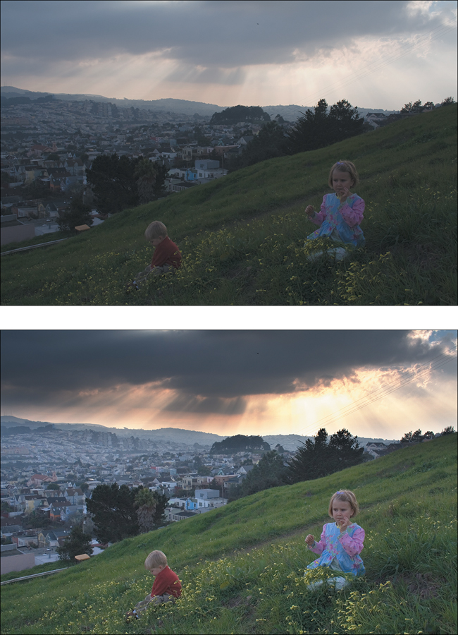
Figure 9.33. The low contrast source (a) of this digital image doesn’t look too hot, yet because it has preserved all color, including the brightest areas of the sky, without clipping, it is possible to recover a good deal of color detail and dynamic range (b).
• If using a small, light camera, mount it to something heavy to move it; that weight reads to the viewer as more expensive and more natural motion.
Lens Artifacts Aren’t Just Accidents
Because this chapter is all about reality as glimpsed by the camera lens, several types of lens artifacts, visual phenomena that occur only through a lens, have already appeared in this chapter, including lens distortion and lens blur (or boke).
You won’t be surprised to hear that this isn’t all: potentially in your palette are more phenomena of the type that professional cinematographers tended to avoid until the 1970s (when they started to be considered cool). These include lens flares, vignettes, and chromatic aberration. None of these occur with the naked eye, but remember, your target is the look of the real world as seen through the camera.
Lens Flares
Lens flares are caused by secondary reflections bouncing around between the camera elements. Because they occur within the lens, they appear superimposed over the image, even when partially occluded by objects in the foreground.
Unlike your eye, which has only one very flexible lens, camera lenses are made up of a series of inflexible lens elements; the longer the lens, the more elements within. Each element is coated to prevent reflection under normal circumstances, but with enough light flooding directly in, reflection occurs.
Artists sometimes like to get goofy and creative with lens flares; how many of us, after all, are experts in how they should look? And yet this is one more area where seemingly unsophisticated viewers can smell something fake under their noses, so certain rules apply.
Zoom lenses contain many focusing elements and tend to generate a complex-looking flare with lots of individual reflections. Prime lenses generate fewer reflections and a simpler flare.
Just as with boke, aperture blades within the lens can contribute to the appearance of flares. Their highly reflective corners often result in streaks, the number corresponding to the number of blades. The shape of the flares sometimes corresponds to the shape of the aperture (a pentagon for a five-sided aperture, a hexagon for six). Dust and scratches on the lens also reflect light.
You can create a lens flare look by hand using solids and blending modes, but most people don’t have the time for this. The Lens Flare effect that ships with After Effects is a rather paltry offering and includes little in the way of customization; you’re best off with Knoll Light Factory (Figure 9.34), which is highly customizable and derived from careful study of lens behaviors, although if you already own Tinderbox 2 from The Foundry, the T_LensFlare is still a vast improvement over the After Effects default.

Figure 9.34. Knoll Light Factory is controlled via a custom interface launched from an Options button in the Effect Controls. Presets such as this one, called “Monkey Planet,” may include dozens of individually adjustable elements, listed right.
More about the behavior and application of lens flares appears in Chapter 12.
Vignettes
Vignetting is a reduction in image brightness around the edges of an image. It’s generally an undesired by-product of certain lenses (particularly wide-angle fisheyes), but it is sometimes deliberately chosen because of how it helps focus attention on the center of frame. I can say with authority that several underwater shots from Pirates of the Caribbean: At World’s End contain vignettes, because I added them myself.
It’s an easy effect to create:
1. Create a black solid the size of your frame as the top layer and name it Vignette.
2. Double-click the Ellipse tool in the toolbar; an elliptical mask fills the frame.
3. Highlight the layer in the Timeline and press F to reveal Mask Feather.
4. Increase the Mask Feather value a lot—somewhere in the triple-digits is probably about right.
5. Lower the Opacity value (T) until the effect looks right; you might prefer a light vignette (10 to 15%) or something heavier (40 to 50%).
Note that the vignette is elliptical, not perfectly round, and if your project is to be seen in more than one format (see below) you’ll have to decide which is the target (Figure 9.35). There would be no reason for a realistic vignette to appear offset.
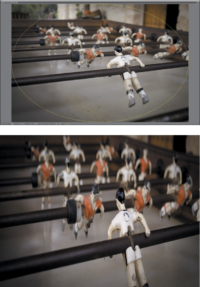
Figure 9.35. A vignette is created with a feathered mask applied to a solid (a). If the image is reframed for display in another format, such as anamorphic, you may have to use that framing instead of the source (b).
Chromatic Aberration
Even further down the road of questionably aesthetic visual phenomena is chromatic aberration, a fringing or smearing of light that occurs when a lens cannot focus various colors on the spectrum to a single point, because of the differing wavelengths. The effect is similar to that of light passing through a prism and dispersing into a rainbow of colors.
Like vignettes, and optically related to lens flares and boke, chromatic aberration is something higher-end lenses are designed to avoid, yet it can occur even under relatively expensive and high-end shooting circumstances, particularly if there is any type of lens conversion happening.
Unlike the others, it can really look like a mistake, so it’s not the kind of thing you would probably add to a clip in order to make it look cool; instead you might add it to a shot or element to match another shot or background plate in which it appears. My recommendation in such a case?
1. Duplicate the layer twice and precompose all three.
2. Use the Shift Channels effect to leave only red, green or blue on for each layer (so you end up with one of each).
3. Set the top two layers to Add mode.
4. Scale the green channel to roughly 101% and the blue channel to roughly 102%.
5. Add a small amount of Radial Blur (set to Zoom, not the default Spin).
A before and after comparison appears in Figure 9.36.

Figure 9.36. A normal (a) and chromatically aberrated (b) image. Chromatic aberration is caused when different wavelengths of light have different focal lengths; most lenses attempt to correct for it with an added diffractive element.
Frame Rate Isn’t Just Speed
One could probably write a whole book or thesis on this one topic alone, but it’s no accident that film images are displayed at 24 frames per second and that newer digital formats, which could theoretically be optimized for just about any frame rate, also aim for this rate (despite how difficult it is to find a low-end camera that shoots 24p natively, with no interlacing).
![]() Close-Up: The Videotape Revolution
Close-Up: The Videotape Revolution
The debate between using 24 fps film and 29.97 fps videotape in the U.S. and other countries with NTSC has been raging since long before the digital era. It began with the advent of videotape in the 1950s, when tape was cheap and fast, if cumbersome by today’s standards.
One particular experiment from this era stands out. For six episodes the producers of The Twilight Zone tried tape before they evidently realized it was ruining the show’s mystique.
Video’s higher frame rate and harder look instantly turned one of the most intriguing and ironic series of all time into something that looked more like a soap opera. To judge for yourself, rent DVDs from Season 2 that include the following videotaped episodes: “Static,” “Night of the Meek,” “The Lateness of the Hour,” “The Whole Truth,” “Twenty-Two,” or “Long Distance Call.”
The question that would generate all of the chatter is “why?” There is no logical answer, and many attempts have been made to explore alternatives. The simple truth seems to be that frame rates of 30 fps and higher feel more like direct reality, but 24 fps is just above the threshold where persistence of vision breaks down, giving it a more ephemeral and dream-like quality, just as do other cinematic conventions such as light bloom and shallow depth of field.
If you have a choice on a given project and you want it to have a cinematic look, try creating it at 24 fps and judge for yourself. After Effects is quite forgiving about letting you change frame rates mid-stream compared with most video applications; details on how the conversion actually works appeared back in Chapter 2.
If you have no choice but to work at 29.97, you still have a choice: progressive versus interlaced. It’s not necessarily an error to render animation without adding interlacing; in fact, step through your favorite animated series on television and you may find that it’s animated at 15 fps or less (and basically never at 59.94 fps, which is effectively what 29.97 fps interlaced means in animation terms). South Park doesn’t count.
The numbers “1.85” and “2.35” give the width, relative to a height of 1, so it’s like saying 1.85:1 or 2.35:1. The 16:9 format, which has become popular with digital video and HD, is equivalent to a 1.77:1 ratio, slightly narrower than Academy, but wide compared to the standard television format of 4:3 (1.33: 1).
Format Isn’t Just Display Size
As the world transitions from standard-definition to high-definition broadcast television, formats are undergoing the same transition that they made in film half a century ago. The nearly square 4:3 aspect is being replaced as standard by the wider 16:9 format, but 1.85 Academy aperture and 2.35 Cinemascope also appear as common “widescreen” formats.
A lot of artists (students, particularly) fall in love with the widescreen look for how it conjures Star Wars and Lawrence of Arabia, but if these formats aren’t shown at 24 fps and don’t obey other cinematic conventions outlined here, the result tends to appear a bit cheesy. So remember, it’s a convention we associate with film, whether or not we know the following history.
In response to the growing popularity of television in the 1950s, Hollywood conjured up a number of different widescreen formats through experiments with anamorphic lenses and film stocks as wide as 70 mm. These systems—CinemaScope, VistaVision, Panavision, and so on—haven’t completely faded away, but their presence in the modern era is mostly felt in the way that films are displayed, not how they are shot. 35 mm is once again the most popular shooting format, specifically the full-aperture version known as Super 35 mm.
Standard 35 mm film has an aspect ratio of 4:3, which is not coincidentally the same as a television. Almost all current movies are filmed in this format as if originally intended for the small screen. When shown in a theater using a widescreen aspect of 1.85:1 (also known as 16:9, the HDTV standard) or 2.35:1 (CinemaScope/Panavision), the full 4:3 negative is cropped (Figure 9.37). Theater patrons actually pay $10 to see less than if they waited for the movie to get broadcast full screen on cable!

Figure 9.37. The “wider” film formats might more accurately be called “shorter” because they typically involve cropping the original 4:3 image.
Color Can Be Much More than Pretty
The influence of color decisions on the final shot, and by extension on the story being told in the shot, is an immense topic, hashed over by cinematographers and colorists the world over. Any attempt to distill this into a few pithy paragraphs would be a disservice.
Thus, if you’re new to the idea of developing a color look for a film or sequence, look at references. Study other people’s work for the effect of color on the mood and story in a shot, sequence, or entire film. Figures 9.38a and b show a couple of third-party tools designed specifically to give a particular look or mood to your shot.

Figures 9.38a and b. Two plug-ins from Red Giant Software aim to let you add color looks like a pro. Colorista (a) is a three-way color corrector superior in fundamental ways to those found in most nonlinear editing packages including Premiere Pro. Magic Bullet Looks 3 opens up a separate user interface and can deliver looks that go beyond just color, such as a diffusion effect (b).
Conclusion
And really, you’ve just scratched the surface of what’s possible. The inventive compositor can and should always look for new methods to replicate the way that the camera sees the world, going beyond realism to present what we really want to see—realism as it looks through the lens.