Processing of nanotube-based nanocomposites
Abstract:
With the continuing developments in materials synthesis and characterization at the nanoscale the potential of true materials tailoring has been enhanced substantially. In general this class of materials involves structures that have at least one dimension at the nanometer scale (usually taken to be up to 100 nanometers). The utilization of nanoscale fibers in polymer composites not only enables the development of uniquely created structures but also provides a means for the development of unique properties and functionalities at levels not possible with conventional fiber reinforced composites. It is the goal of this chapter to introduce the advances in carbon nanotube (CNT) nanocomposite research with specific emphasis on processing routes used to disperse, align and fabricate carbon nanotube reinforced polymer nanocomposites for enhanced physical and mechanical properties. Acknowledging that the potential for CNTs as reinforcement and conductive media has not yet been fully realized, a discussion on future trends is also given.
1.1 Introduction
1.1.1 Nanoscience and composites
With the continuing developments in materials synthesis and characterization at the nanoscale the potential of true materials tailoring has been enhanced substantially. In general this class of materials involves structures that have at least one dimension at the nanometer scale (usually taken to be up to 100 nanometers). Remarkable progress has been made regarding the use of carbon nanotubes (CNTs) to reinforce polymer matrices since the helical tube geometry of carbon nanotubes was first discovered by Iijima in 1991 (Iijima, 1991). As the name implies, CNTs are cylindrical tube structures of varying lengths made of carbon atoms. They exist as either single-walled carbon nanotubes (SWCNT) or multi-walled carbon nanotubes (MWCNT) where individual tubes are nested concentrically inside one another like tree rings. These unique nanostructures are considered one-dimensional due to their high aspect ratio (length-to-diameter) leading to superior mechanical and electrical properties. The diameter and chirality of the CNTs produce either metallic (conducting) or semi-conducting nanotubes. Additionally, their anisotropic nature makes CNTs interesting reinforcing fibers for multi-functional ultra-light, high strength and stiffness composite materials and devices. Compared with carbon fibers, the very high modulus versions of which have elastic moduli of over 750 GPa, the elastic moduli of CNTs have been measured in the range of 1–4.7 TPa (Cooper et al., 2002; Lau et al., 2006). The tensile strength is also approximately two orders of magnitude higher than that shown by currently available carbon fibers (Cooper et al., 2002). In addition, the change in diameter of these materials also results in a significant increase in surface area for the same volume fraction in a composite, leading to a variety of very interesting characteristics. For example, a 30 nm diameter nanotube has 150 times more surface area than a 5 μm diameter carbon fiber for the same filler volume fraction (Eitan et al., 2006).
The utilization of these fibers in polymer composites not only enables the development of uniquely created structures but also provides a means for the development of unique properties and functionalities at levels not possible with conventional fiber reinforced composites. Several comprehensive reviews of carbon nanotube reinforced polymer composites have been published over the last few years (Bal and Samal, 2007; Coleman et al., 2006; Hussain et al., 2006; Thostenson et al., 2001, 2005; Gibson et al., 2007; Xie et al., 2005; Wang et al, 2004). It is the goal of this chapter to introduce the advances in CNT nanocomposite research since the publication of these reviews with specific emphasis on processing routes used to disperse, align and fabricate carbon nanotube reinforced polymer nanocomposites for enhanced physical and mechanical properties.
1.1.2 Aspects for consideration
Just as on the macroscale, the properties of the nanocomposite are dictated by the distribution, orientation and fiber/matrix interactions. Because nanotubes tend to form clusters and bundles, the biggest challenges on the nanoscale are to fully disperse individual nanotubes in the matrices and achieve good interfacial adhesion between them and polymer for load transfer capabilities. The tendency for the reinforcement to agglomerate persists unless high shear forces are applied by vigorous mixing of the polymer. However, the mixing intensity must be controlled since overmixing often damages CNT structures, compromising their properties. Another issue is that the polymer-nanotube mixtures are highly viscous (due to the large surface area of nanotubes). This creates process-related problems, because the composites do not flow easily and are hence more difficult to mold. Viscosities of nanotube-filled polymers are known to show abrupt increases above fairly low loading thresholds following a Schulz-Blaschke type response. Processing is also hindered by the poor compatibility of nanotubes with most solvents and polymers. Nevertheless, several approaches have been successfully adopted to obtain intimate mixing of nanotubes with polymer phases, including dry powder mixing, melt mixing, polymerization of monomers onto and surrounding CNT surfaces, and surfactant-assisted mixing. More creative processing techniques are still needed. It should be noted that the potential of the mechanical, electrical, and thermal properties offered by nanotubes has not fully been realized and is mostly limited by processing methods. It is in this context that the current chapter provides a state-of-the-art review of the topic, highlighting important advances in a variety of processing routes, and ending with a brief identification of potential future directions.
1.2 Structure of carbon nanotubes
1.2.1 Carbon nanotube morphology
There are two primary types of CNTs available. SWCNTs consist of a single graphene sheet seamlessly wrapped into a cylindrical tube. The one-dimensional nature of the CNTs means that they exhibit electrical conductivity as high as copper, thermal conductivity as good as diamond, and strength levels as much as 100 times greater than steel at a fraction of the weight. The structure of MWCNTs can be thought of as concentrically nested SWCNTs where dimensions such as inner and outer tube diameter are important for strength and conduction. In most cases tube diameter is linearly proportional to tube thickness (due to concentric tube layering). MWCNTs offer higher stiffness than SWCNTs, especially in compression, due to the reinforcing efforts of centrically aligned tubes.
Single-walled carbon nanotubes can exist in three distinct structures: armchair, zigzag and chiral. The packing of the carbon hexagons in the graphitic sheets defines a chiral vector (m,n) and angle. The indices of the vector determine the morphology of the CNT (Hussain et al., 2006). Zigzag structures are identified by (n,0) type indices, while armchair are (m,n), and chiral are (n,m) where n ≠ m. When (m-n)/3 is an integer, the resulting structure is conductive and is termed ‘metallic’. Other variations have semiconductive properties. Therefore all armchair and one-third of zigzag CNTs are metallic, having a continuous conduction band (Hussain et al., 2006). The remaining two-thirds of the zigzag and chiral CNTs are semiconducting, having an energy gap in the conduction band (Hussain et al., 2006).
1.2.2 Synthesis of carbon nanotubes
The mechanisms by which CNTs may be synthesized can be grouped into two categories: ablation of graphite or decomposition of carbon-containing compounds. The main methods of CNT synthesis using graphite sublimation are direct-current arc discharge and laser ablation. Many versions of the arc discharge method have been reported. The main disadvantage of this process is the concurrent formation of amorphous carbon soot, metal clusters coated with carbon and non-tubular fullerenes along with CNTs (Rakov, 2006). Such inefficiencies limit the production of SWCNTs to a 20–40% yield. Additionally, the SWCNTs produced this way are generally entangled, with poor linear orientation. SWCNT synthesis by laser ablation was first achieved by Smalley using a pulsed laser that strikes a target of graphite and a metal catalyst such as Co or Ni (Scott et al., 2001). The laser vaporization plume condenses on a collector outside the reaction chamber to form the SWCNT structure. Another common technique for the production of SWCNTs is electric arc discharge in which carbon is vaporized between two graphite electrodes acting as the anode and the cathode. When a direct current (dc) voltage is applied, large quantities of electrons from the arc-discharge move to the anode and collide onto the anodic rod. Upon cooling, the electrode deposits condense on the cathode. The contents contain carbon nanotubes, nanoparticles, and clusters. Therefore, when comparing laser ablation and arc-discharge synthesis methods, the nanotubes produced by laser ablation are purer (up to about 90% pure) than those produced in the arc process (Scott et al., 2001).
Chemical vapor deposition (CVD) is based upon the mechanism of decomposition of carbonaceous compounds to grow vertically aligned CNT arrays of controlled length. In this process a continuous supply of carbon-containing vapor is introduced into a reaction furnace at elevated temperature (Deck and Vecchio, 2006). Carbon is deposited onto conductive seed particles which can be patterned onto a silicon wafer to produce uniquely designed CNT arrays. Fang et al. (2005) used a CVD process to grow vertically aligned MWCNTs on a thin polysilicon film deposited on top of a silicon wafer. An iron film is then deposited and patterned onto polysilicon by means of a lift-off technique. Aligned MWCNTs were grown by CVD using acetylene as the precursor at 800°C in an Ar/H2 flow for 10 minutes. This method has been shown to produce more intricate patterns of aligned MWCNTs depending upon the seed particle (Fe) patterning.
Plasma enhanced CVD (PECVD) results in further CNT uniformity within the array. Figure 1.1 shows the controlled length and diameter of vertically aligned MWCNTs grown from the PECVD of acetylene on a silicon wafer. Of all the synthesis techniques, variations of the CVD process show the most promise for economically viable, large-scale synthesis of high quality CNTs. Even so, there is no clear understanding of the influence of key parameters (temperature, pressure, carbon source) on CNT properties (diameter, length, and morphology), which shows that further research is necessary to optimize this process (See and Harris, 2007). Recent work has focused on scaling-up production of SWCNTs to supply large quantities to meet the demands of implementing CNT reinforced composite devices in a variety of application fields. A scaled-up pulsed laser vaporization process also shows promise for high production of SWCNTs to produce up to 10 g/day SWCNT (Rinzler et al., 1998).

1.2.3 Carbon nanotube surface treatments
Surface treatments such as oxidation and chemical functionalization of CNT sidewalls and endcaps assist in the separation of bundles and entanglements. Acid etch pretreatments are often used as a means of purifying the CNTs and removing catalyst ‘seed’ particles that result from the CVD synthesis process. Just as macroscale fiber sizing promotes interfacial adhesion, chemical functionalization on the surface of the CNTs improves interaction with the polymer matrix at the nanoscale of the composite.
Functionalization along CNT sidewalls offers more coverage area than on endcaps and thus a higher capacity for property enhancement. Possible surface treatments include the attachment of functional groups or the grafting of low molecular weight polymers to the CNTs by covalent interactions or by adsorption where weaker secondary bonding interactions take place. Covalent bonding to CNT surfaces can be achieved through the attachment of chemical functionality to carboxylic acid groups on the CNT surface as a result of the acid etch treatment, or through direct bonding to surface carbon double bonds.
Oxidation
Oxidation of CNT surfaces is typically the starting point for various functionalization techniques. Oxygen-containing carbonyl, carboxylic acid and hydroxyl moieties can be easily introduced via an acid treatment which also helps to purify the CNTs by removing elemental impurities. Concentrated HNO, and mixtures of H2SO4 with HNO3, H2O2, or KMnO4 have been used for attaching oxygenated functionality to CNTs. However, excessive acid treatments may result in a decrease in physical properties. Functionalization by vigorous oxidation processes followed by covalent bonding has been shown to introduce defect sites where sp2 hybridization is converted to sp3 hybridization, which may affect the properties of the nanotube itself (Odegard et al., 2005).
As a precursor for CNT functionalization, the oxidation conditions were explored by Hong et al. (2007), who indicated that MWCNTs were damaged during the oxidation process and became shorter. As the temperature of the oxidation step increased the CNT length decreased; however, with increasing oxidation time, the length distribution becomes comparatively narrow with an optimal oxidation time around 10 min for acid oxidation at 80°C. While physical properties of CNTs may be diminished with decreasing CNT length, the shorter lengths have been shown to aid in the dispersion of MWCNT in polypropylene (PP) composites (Hong et al., 2007). Jin et al. (2007) also found that nitric/sulfuric acid treated CNTs showed a lower degree of entanglement due to shorter length. Another technique showed that the exposure of CNTs to CO2/Ar plasma optimized with respect to time, pressure, power and gas concentration resulted in 14.5 at% in the first atomic layers forming hydroxyls, carbonyls, and carboxyl groups as detected by X-ray photoelectron spectroscopy (XPS) (Andrews and Weisenberger, 2004). Bubert et al. (2003) used plasma to introduce oxygen-containing functional groups to the surface of carbon nanotubes, resulting in polar groups being formed on the surface and a modified surface morphology which was shown to increase the adhesion between CNTs and a polymer matrix. Optimal treatment conditions were found to include the use of carbon dioxide as the plasma gas, a low pressure of approximately 0.1 hPa, a low plasma power of approximately 80 W or less and a treatment time of not more than 3–5 min.
Polymer grafting
Functionalization not only increases dispersibility in various solvents and polymers but also increases the strength of the interface between CNTs and the polymer (Andrews and Weisenberger, 2004). Poly(vinyl alcohol) (PVA) has been used to functionalize SWCNTs to render them dispersible and stable in water (Vandervorst et al., 2006) and to create a dissipative interface for introduction into a poly(butyl acrylate) latex dispersion (Wang et al., 2006). Hwang et al. (2004) showed that emulsion polymerization, when used to graft polymethyl methacrylate (PMMA) onto the surface of MWCNTs prior to their addition to PMMA at loadings up to 20%, would result in a significant increase in elastic modulus when processed using solution casting in a chloroform solvent. The in situ emulsion polymerization of monomer butyl acrylate (BA) or methyl methacrylate (MMA) has also been shown to proceed while CNTs are redispersed, consequently coating the CNTs, resulting in yield strength increases of about 31% and elastic modulus increases of about 35% at only 1.0 wt% polymer encapsulated MWCNTs dispersed in polymide 6 (PA6) (Xia et al., 2003). Graft polymerization via plasma chemical vapor deposition has also been shown to produce PMMA coating on MWCNT, which can then be processed via melt mixing and drawing, causing a significant improvement in mechanical properties compared with pure PMMA (Gorga et al., 2006). Functionalized MWCNTs with PMMA via i n situ polymerization have also been demonstrated to result in improvement of 94% in elastic modulus, 360% for ultimate tensile strength, 373% for breaking strength, 1282% for toughness, and 526% for elongation at break with less than 0.5 wt% MWCNTs (Blond et al., 2006).
Amine-functionalized CNTs have received a lot of research attention because of the potential for covalent bonding with epoxy resins. A comprehensive review of fluorinated trichlorosilane functionalization of MWCNTs was provided by Vast et al. (2004) and is hence not repeated herein. Amine terminated CNTs have been shown to increase the modulus, tensile strength, and elongation at break when introduced into natural rubber due to high polymer/CNT interaction between the silanized CNT and natural rubber vulcanizates (Shanmugharaj et al., 2007). Amino functionalization makes the CNTs very effective crosslinking agents. Zhu et al. (2004) demonstrated that the functionalized CNTs form strong covalent bonds during the cure of epoxy matrices and hence become an integral part of the crosslinking system. Ramanathan et al. (2005) explored two techniques for introducing amine functionalization to the surface of SWCNTs. In the first approach, carboxylated SWCNTs were treated with ethylenediamine in a controlled reaction to link the free amine group to the SWCNTs to form amide functionality, while the second approach involved the reduction of the carboxyl group to hydroxymethyl, followed by transformation into aminomethyl groups. In both approaches, amine groups are tethered to the CNT surface, which is available for reaction with a variety of reactive polymers. Diamine-MWCNTs can be obtained from the reaction between acid-treated MWCNTs and 1,10-diaminodecan (DA10) with the lower degree of aggregation in functionalized MWCNTs being attributed not only to the functional drops, such as carboxyl and diamine, but also to their shorter lengths (Jin et al., 2007).
Gamma-radiation
Guo et al. used γ-irradiation to prepare various functionalized modifications on CNTs, through the formation of an amine bond wherein the concentration of functional groups bound to the CNT increased due to the number of defect sites created by γ-photons (Guo et al., 2005).
Mechanochemical milling
The large-scale production of functionalized short CNTs using mechanochemical ball milling has also been shown to introduce functional groups such as thiol, amine, amide, carbonyl and chloride onto the surface of MWCNTs (Konya et al., 2002), providing a cheaper, albeit less uniform, mechanism of surface treatment.
1.3 Processing methods for nanotube-based polymer nanocomposites
1.3.1 Solution blending
Perhaps the most commonly applied processing technique for carbon nanotube polymer composites is the solution mixing or solution blending technique. Solution processing of CNT/polymer composites involves the dispersion of nanotubes in a polymer solution by energetic agitation, controlled evaporation of solvent and finally composite film casting. Agitation can be done by magnetic stirring, shear mixing, reflux or, most commonly, sonication. Sonication or ultrasonication excitation of filler/resin mixtures breaks up CNT clusters through cavitation (nucleation and collapse of bubbles) in the liquid and/or exciting resonant vibrations of the clusters. Sonication can be achieved either by immersing a beaker of solution of CNT in solvent in an ultrasonic bath or by partially submerging an ultrasonic wand (tip or horn) directly into the CNT/solvent solution. The processing parameters, such as CNT weight percent, bath and tip sonication, sonication times, surfactant type and solvent type, have an effect on the dispersion of SWCNTs in the bulk polymer.
Solution-based processes make use of low viscosities to facilitate mixing and dispersion. Many studies have used this method for processing of both thermosetting and thermoplastic polymers. The appropriate selection of a solvent is crucial to the efficacy of the process since it must not only provide complete dissolution of the polymer matrix material but also ensure the attainment of an appropriate viscosity to evenly disperse CNTs with the aid of sonication. Khan et al. (2007) studied the effect of solvent choice on the mechanical properties of CNT/polymer composites via a solution drop-casting technique and demonstrated that the removal of solvent from the CNT/polymer system also plays a critical role in the physical properties of the composite, with the Tg decreasing if there is residual solvent due to the build-up of solvent at the CNT/polymer interface.
Thermoplastic polymers
Solution blending of thermoplastics begins with the dissolution of the polymer in a solvent. Esawi and Farag (2007) observed that the selection of a solvent can influence the mechanical performance of the composite, as shown in Table 1.1.
Table 1.1
Mechanical properties of PVA and double-walled CNTs/PVA composites as a function of solvent selection and drying time

Source: Adapted from Esawi and Farag (2007)
Solution mixing may be done at room temperature or with the application of external heat to accelerate the thermodynamic dissolution process. The nanotubes are then added to the liquid polymer solution and mixed via ultrasonication. To assist in the complete dispersion of nanotubes, a suspension may be created with CNTs in solvent prior to being combined with the polymer solution. Once ultrasonication is completed for the polymer solution with nanotubes, the mixture can be cast in a mold. Film casting may be done in a vacuum oven to assist in the solvent removal; however, it has been observed by the authors that slow evaporation of solvent (no vacuum oven) yields a composite with higher polymer crystallinity than a more rapid solvent evaporation method (Love and Karbhari, 2007).
Li et al. (2004) used ultrasonication to successfully disperse 10 wt% MWCNTs in ethylene-co-vinyl acetate (EVA) by using solution processing technique in a mixture of solvent oil and ethanol wherein the CNTs were observed to act as nucleating agents and hence noticeably increased the crystallization temperature of the EVA. Foster et al. (2005) explored the effect of solvent choice on SWCNT dispersion in polystyrene (PS) and thermoplastic polrethane (TPU) matrices using a dip-coating method and reported that, while toluene and chloroform should be disregarded due to poor dispersion characteristics, 1-methyl-2-pyrrolidinone (NMP), which dissolved both PS and TPU, provided adequate dispersion quality and stable suspension even after several months of storage. It is noted that the solution casting method is capable of producing high CNT loading up to 50 wt% with reasonably good dispersion (Coleman et al., 2006), with MWCNT dispersed in water and blended with poly(vinyl alcohol) in water yielding even as high as 60 wt% nanotube composites.
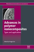
Both the choice of solvent and sonication time have a profound effect on the distribution of CNTs in composites. Safadi et al. (2002), for example, were able to dissolve PS in toluene with MWCNTs and use sonication to cast thin film composite of random orientation CNTs with thickness 100–400 μm, whereas Qian et al. (2000) found the optimum sonication time needed for complete dispersion increased with CNT length (30 min for 15 μm length and 1 h for 50 μm length) for the case of MWCNT solvent cast in PS with ultrasonic wand at 150 W. The variable distribution quality of MWCNT in a thermoplastic matrix process via solution casting is shown in Fig. 1.2. Insufficient sonication time results in the presence of MWCNT bundles.
1.2 SEM fracture surface of a solvent cast MWCNT/reactive ethylene terpolymer composite illustrating (a) dispersion of individual MWCNTs with some agglomerations, (b) close-up of MWCNT agglomeration identified by arrow. (Copyright, Dr Corey Love, University of California-San Diego, 2007.)
Peng et al. (2006) used an electrostatic-assembly solution technique to evenly disperse and distribute CNTs and polymer particles in an aqueous suspension. MWCNTs underwent an acid etch process to introduce oxygenated surface functionality to the CNT walls, making them negatively charged. Polymer particles of PMMA prepared by soap-free emulsion polymerization were dispersed in a cationic surfactant in water. Electrostatic coupling between the negatively charged CNTs and positively charged PMMA particles facilitates the formation of dispersed and distributed filler networks. The water is removed by vacuum heating and the CNT/polymer particles are fused at elevated temperature to create composite films.
The solvent choice is generally made based upon the solubility of the polymer. Some pure CNTs may not be easily dispersed in specific solvents. To overcome this, a surfactant may be used to break up CNT bundles and entanglements. The most commonly used surfactant is sodium dodecylsulfate to (SDS), which has been demonstrated to assist the dispersion of MWCNTs in epoxy at levels between 0.01 and 0.5 wt% CNT loading (Fidelus et al., 2005). The use of an anionic surfactant such as polyoxyethylene 8 lauryl (C12EO8), as a wetting/dispersing agent, in water has also been shown to stabilize CNTs, leading to good dispersion of MWCNTs (Dalmas et al., 2005) and to improve the Tg from 63°C to 88°C and increase the elastic modulus more than 30% over an unreinforced epoxy (Gong et al., 2000). The non-ionic surfactant contains a hydrophilic oxyethylenated segment, which essentially interacts with the resin via hydrogen bonding, while the hydrocarbon hydrophobic segment acts as a dispersing agent for carbon where steric repulsive forces overcome the van der Waals bundling forces and facilitate CNT dispersion.
Thermosetting polymers
Epoxy systems are the most commonly used matrices in thermosetting resin composites. Typically, CNTs are dispersed in the resin via sonication. Solvents are added to lower the solution viscosity. A catalyzing agent or hardener is then added to initiate the formation of chemical crosslinking under an exothermic reaction. While composites have been successfully formed by pouring into a cast (after dispersing the nanotubes in a solution of a block copolymer in ethanol solvent, followed by the addition of the liquid epoxy, and removal of the ethanol by evaporation), CNTs have also been efficiently dispersed ultrasonically for as long as 48 hours in dichloroethane or N-N-dimethylformamide to form a stable solution into which the epoxy was then dissolved and the suspension placed under vacuum to remove trapped air for 1 h at 130°C, followed by the addition of a curing agent to cure at room temperature for 2–4 days before a 2-h post-cure bake at 120°C (Biercuk et al., 2002).
Gojny and Schulte (2004) in contrast dispersed functionalized and non-functionalized MWCNTs in a polyetheramine curing agent rather than the epoxy resin prior to curing and attributed the high dispersion quality to the long chain polar solvent interacting with functionalized CNTs, causing stabilization of the nanotube suspension. For epoxy resins with UV curing no hardener is needed to initiate crosslinking and curing since excitation by UV light initiates the cure. CNT composites have been formed in this medium by dispersing them in chloroform solution before pouring into a photoresist epoxy resin, followed by further curing carried out by baking (Coleman et al., 2006).
While solution casting offers many significant advantages for processing nanocomposite materials, there are several issues which must be addressed, chief among which are the large quantity of highly toxic solvents needed for polymer dissolution and the eventual environmental health and safety hazard posed by the CNT dispersion (Barraza et al., 2002).
1.3.2 Melt mixing
Melt blending of thermoplastic polymers as a processing technique for the incorporation of fillers and fibers has existed for some time. The reversible thermo-physical nature of thermoplastics makes melt blending possible with carbon nanotube reinforcements. The combination of thermal stimulation (melting) and high shear mixing forces provides the necessary energy to disperse nanotubes in thermoplastic matrices. However, relative to solution blending methods, melt blending is generally less effective at dispersing nanotubes in polymers and is limited to lower concentrations due to high viscosities of the composite at higher nanotube loadings (Moniruzzaman and Winey, 2006). For polymers which are not readily soluble, such as most thermoplastics, melt processing is an acceptable alternative. As a general rule, amorphous polymers may be processed above their glass transition temperature while semi-crystalline polymers must be heated above their melting temperature. The application of heat for melting polymers creates a viscous ‘gel’ to which CNTs may be added and mixed using standard mixing techniques using mall laboratory benchtop mixers. The use of a larger standard Haake internal mixer by Thermo-Electron Corp. has obtained good dispersions and distributions (Lozano and Barrera, 2001).
As the mixing energy is increased, the dispersion quality increases. This can be done by increasing the mixing time or speed. However, energy input from shear mixing can break nanotubes into shorter segments with lengths decreasing up to 75% of their original, decreasing their aspect ratio in the final composite while simultaneously improving their dispersibility (Andrews and Weisenberger, 2004). MWCNTs have been fairly uniformly dispersed in HDPE by the shearing action of a twin-screw extruder where small aggregates of MWCNTs are evenly dispersed on a size scale of 10 μm or larger (Tang et al., 2003).
Good dispersion using a dilution technique was confirmed via AFM and TEM investigations for MWCNTs melt mix compounded and extruded with polycarbonate (PC) (Potschke et al., 2004). Starting from a high concentration of MWCNTs in PC masterbatch, subsequent PC was added to dilute to the desired composition. A percolation threshold for electrical conductivity was observed at 1.5 wt%. In another work, the optimal conditions for MWCNTs in PS, PP and aminobenzene sulfonic acid (ABS) were found to be 20 rpm for 15 min, which was adequate for complete dispersion (Andrews et al., 2002a).
Often a combination of melt processing techniques is employed to produce a high degree of CNT separation. Melt mixing prior to extrusion is often important for producing accurate CNT loading levels, since the CNTs can stick to the walls of the hopper, making the final composition less than the desired weight fraction. There are several advantages of using melt mixing methods of process CNT/polymer composites, most notably the speed, simplicity, and compatibility with industrial techniques. Important parameters to consider for shear mixing of nanocomposites include temperature, mixing time, rotor speed, and CNT concentration.
Extrusion
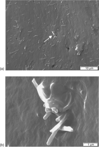
The extrusion processing parameters on the dispersion quality of MWCNTs in HDPE have been studied by Zou et al. (2004), who concluded that at low screw speeds large agglomerations of loosely bound MWCNTs occur in a bundle form. This occurs since, with an increase in MWCNT loading, the average energy the screw can transfer to the filler agglomerate is decreased such that the lower the screw rate, the poorer is the dispersion and the bigger the agglomeration of MWCNTs. Dispersion quality was found to be higher at 150 rpm than at 80 rpm, as shear thinning effects at high screw speeds prevent the formation of large agglomerations by breaking them into smaller particles. Similar findings by Li and Shimizu (2007) showed improved dispersion with increasing screw rotation speed, with the optimal screw speed for MWCNTs in a thermoplastic elastomer as high as 2000 rpm, as shown in Table 1.2.
Table 1.2
Mechanical properties of neat SBBS and its composites processed at various screw shear rates containing 3 wt% MWCNT
Source: Adapted from Li and Shimizu (2007).
Injection molding
While extrusion has been shown to result in the best dispersion quality, injection molding of MWCNT composites is often resorted to as a second step in fabricating individual components using extruded pellets as a means of enhancing overall shape complexity and speed.
Dynamic packing injection molding (DPIM)
Dynamic packing injection molding has been shown to control polymer morphology and mechanical properties of filled thermoplastics. The main feature of this technology is that the specimen is forced to move repeatedly by two pistons that move reversibly with the same frequency during cooling, resulting in preferential orientation of the dispersed phase or filler as well as the matrix. Polypropylene/MWNT composites with good dispersion have also been prepared by the DPIM with enhancement in tensile strength and impact strength at very small loadings of MWNTs (only 0.6 wt%). The repeated shear force offered by DPIM is powerful enough for the dispersion of MWNTs in polymer matrix.
Compression molding
Compression molding or hot press molding has been successfully demonstrated by Haggenmueller et al. (2000), who cut a masterbatch solvent cast composite of 10 wt% SWCNT PMMA into segments of 1–1.5 cm2, which were then stacked together and hot pressed between 180°C platens for 3 min under 3000 lb pressure. The resulting 50–100 μm thick films were subsequently cut into pieces again and re-pressed, with the procedure being repeated as many as 25 times to achieve complete dispersion of SWCNTs in PMMA, where the dispersion increased with each additional melt cycle.
1.3.3 In situ polymerization
The in situ polymerization of nanocomposites can be described as a ‘bottom up’ approach to composite manufacturing, wherein nanotubes are dispersed in a monomer solution which is then polymerized to form a solid-state composite. The advantage of bottom-up fabrication is that interaction at the molecular level allows high nanotube loadings and good miscibility with almost any polymer type. This technique is particularly important for insoluble and thermally unstable polymers which cannot be processed by solution or processed through melting techniques. Depending upon the required molecular weight and molecular weight distribution of polymers, chain transfer, radical, anionic, and ring-opening metathesis polymerizations can be used for in situ polymerization. The introduction of hydroxyl, carboxyl and isocyanate groups on the surface of MWCNTs has been shown to catalyze the ring-opening reaction of benzoxazine (Chen et al., 2006), with the reaction of the isocyanate group with the phenolic hydroxyl groups generated by the ring-opening of benzoxazine resulting in significantly improved polybenzoxazine (PBZ) MWCNT interfaces.
Jia et al. (1999) used in situ radical polymerization in conjunction with PMMA using a 2,2’-azobisisobutyronitrile (AIBN) radical initiator such that the π-bonds in carbon nanotubes were initiated by AIBN and therefore the nanotubes could participate in PMMA polymerization to form a strong interface between the MWCNTs and the PMMA matrix. Addition polymerization was used to produce PMMA/MWCNT composites. In this process, 0.08 wt% of free radical initiator-AIBN (2,2’-azobisisobutyronitrile) was added into MMA at the reaction temperature of 358–363 K, at which an AIBN molecule yields N2 and forms two free radicals, which causes the double-bonded MMA to open and polymerize. Their findings indicated that the CNTs may take part in the polymerization process, as more AIBN is consumed in the presence of CNTs, causing an opening of the p-bonds linking the CNTs to PMMA. This bond resists the growth of PMMA but may produce a single C–C bond, creating a strong interface between CNT and PMMA. Velasco-Santos et al. (2003a) later used the same initiator to incorporate non-functionalized and carboxyl functionalized MWCNTs into a PMMA matrix.
In situ hydrolytic polymerization of e-caprolactam can be completed in the presence of pristine and carboxylated nanotubes since the monomer of e-caprolactam forms electron-transfer complexes with the MWCNTs, giving a homogeneous polymerizable master solution which facilitates the formation of composites with homogeneously dispersed nanotubes. Gao et al. (2005) improved upon the technology by adding a continuous spinning technique to form PA6 fibers by ring-opening polymerization of caprolactam in the presence of SWCNTs, resulting in the formation of a new hybrid material with excellent compatibility between SWCNTs and PA6.
Acid purified MWCNTs have also been added to PMMA via an in situ polymerization technique (Park et al., 2003) in which the radicals induced on the MWCNT by AIBN were found to trigger the grafting of PMMA. During polymerization MWCNTs consumed the initiator AIBN by opening π-bonds on the MWCNT surface to form radicals, as a result of which the molecular weight of PMMA increased with the MWCNT content.
Xia et al. (2006) reported on the use of ultrasonication as a means of initiating polymerization of monomers without a chemical initiator. The rigorous nature of the sonication process elevates temperature and pressure to the level where radicals can be generated due to the decomposition of water or monomer surfactant, or through the rupture of polymer chains to initiate polymerization of the monomer.
Electropolymerization
Wanekaya et al. (2006) studied the electropolymerization and characterization of polypyrrole films doped with poly(m-aminobenzene sulfonic acid) (PABS) functionalized SWCNTs (PPy/SWCNT-PAB S). This functionalization makes the SWCNTs water-soluble and negatively charged, resulting in the SWCNT-PAB acting as anodic dopants during the electropolymerization of pyrrole monomer between an applied potential of − 0.65 V and 1.05 V with a galvanostatic sweep rate of 50 mV/s to synthesize the composite. Scanning electron microscopy (SEM) and Atomic Force Microscopy (AFM) studies indicate that the use of doped SWCNT-PAB significantly changes the morphology of polypyrrole and the composite film forms a porous and cross network (Wanekaya et al 2006). The addition of PBS-functionalized SWCNTs improved the electronic performance when compared with pure PPy.
Inverse microemulsion
An inverse microemulsion, which consists of oil, surfactant, and water molecules, is a thermodynamically stable and isotropic transparent solution and is used to form layers on substrates through trapping of microdrops of an aqueous phase within assemblies of surfactant molecules dispersed in a continuous oil phase. Yu et al. (2005) demonstrated an approach to the preparation of MWCNT/polypyrrole (PPy) core-shell nanowires by in situ inverse microemulsion wherein the CNTs were evenly coated with a thin coating of PPy of the order of tens of nanometers through the precipitation of inorganic nanoparticles onto the nanotube surface. Strong interaction between the π-bonded surface of the carbon nanotubes and the conjugated structure of the PPy shell layer was deduced from FTIR spectra. This approach provides a simple and reproducible procedure in which the thickness and adherence of the coating are fairly easily controlled by the monomer concentration and the reaction conditions.
1.3.4 Mechanochemical pulverization
Mechanochemistry deals with stress-induced chemical reactions and structural changes of materials, and mechanochemical processes such as high-energy ball milling, vibromilling, pan milling and jet milling are typically used to prepare ultrafine metal, ceramic or polymer powders. The benefit of mechanochemical pulverization is the production of CNT/polymer composite powders which can then be processed using a number of melt processing techniques such as extrusion, injection molding, compression molding, and melt spraying. Repetitive milling cycles reduce the particle size even further. Xia et al. (2004) used mechanochemical pulverization (pan milling) to prepare 3% MWCNT/PP composite powders which were subsequently melt-mixed with a twin-roll masticator to obtain composite sheets. During the pan milling process, high shear radial and tangential forces cause a reduction in particle size and chain scission of polymers. The ground CNTs are attached to the milled polymer particles via adsorption. After 20 milling cycles the average particle size was reduced to a few microns. It should, however, be noted that milling does have a detrimental effect on CNT geometry as the high shear forces cause the average CNT length range to decrease from 1–10 μm to 0.4–0.5 μm, although the CNTs do become straighter and are more uniform in size (Xia et al., 2004).
1.3.5 Electrostatic assembly
The electrostatic interaction between cationic polystyrene (PS) latex and anionic carbon nanofibers provides a ‘bottom-up’ synthesis method for a composite in which a cationic polystyrene latex was synthesized by emulsion polymerization and mixed with an aqueous suspension of oxidized carbon nanofibers, resulting in a material form obtained through hetero-coagulation. The final product is formed through a subsequent compression molding step. Xu et al. (2005) found that the percolation threshold was below 2 wt% (1 vol%) carbon nanofibers in PS in this case.
1.3.6 Alternative processing techniques
In addition to the more conventional techniques described earlier, other alternate processing routes also exist for nanofiber based composites. Hassanien et al. (2001) showed the potential of electrochemical deposition of conducting polymer films onto individual nanotubes. A novel spray-coating technique was developed by Zhang et al. (2006) to cover ultrahigh molecular weight polyethylene (UHMWPE) particles with SWCNTs, which were then processed through dissolution of the SWCNT/UHMWPE particles in xylene solvent, forming a composite with a three-dimensional network having a threshold composition of 0.6% SWCNTs in UHMWPE, which improved electrical conductivity by nine orders of magnitude. Safadi et al. (2002) used a spin casting technique to form thin PS/MWCNTs composite films of 30–50 μm. In this case the nanocomposites were constituted of an amorphous poly(styrene-co-butyl acrylate) latex as a matrix material with MWCNTs as fillers. Regev et al. (2004) demonstrated that SWCNTs can be easily integrated into a PS or PMMA matrix by dispersing SWCNTs in a surfactant which is added to a latex nanoparticle suspension obtained by emulsion polymerization. When the surfactant and water are removed, the remaining polymer nanoparticles and absorbed SWCNTs can be melt processed by compression molding.
1.4 Nanotube alignment
Typical solution casting techniques result in nanocomposites with random orientation of CNTs. However, in addition to structural rationale, CNT alignment is desired for anisotropic applications such as in conductivity and thermal management devices. A comprehensive review on the development of aligned and micro-patterned carbon nanotubes was published by Dai et al. (2003). The alignment of carbon nanotubes for reinforcing polymer materials to form composites will be discussed in this section with a focus on in-plane and transversely aligned systems.
1.4.1 In-plane alignment
Melt drawing
Thostenson and Chou (2002) successfully dispersed and aligned prefabricated MWCNT/PS solution cast composites by post-processing with a twin-screw extruder though a rectangular die (13 mm x 0.35 mm) with a 100 rpm screw speed and drawing the film prior to cooling at various take-up rates. The drawing alignment of CNTs in PS caused a significant improvement in elastic modulus compared with extrusion compounded composites without the drawing step. Additionally, increases in yield strength and ultimate strength indicated an improvement in load transfer capability between PS and CNTs reinforcements. Ruan et al. (2003) observed the toughening performance of ultrahigh molecular weight polyethylene using MWCNTs aligned via hot-drawing. The final anisotropic films with different draw ratios were obtained by tensile drawing at 120°C using an Instron tensile tester. The composites showed a ductile stressstrain response with the maximum strain at break decreasing with increasing draw ratio. It should be noted that tensile toughness and modulus are also enhanced due to the presence of CNT inclusions. Melt mixing via extrusion coupled with melt drawing has been reported to yield unique modulus, strength and toughness behavior for MWCNT reinforced PP as shown in Table 1.3 (Dondero and Gorga, 2006).
Table 1.3
Mechanical properties for PP and MWCNT/PP composites as a function of CNT concentration and draw ratio

Source: Adapted from Dondero and Gorga (2006).
Drawing fibers not only makes use of CNT anisotropies, but also causes stress fields unique to the processing method, which, even in unfilled polymers, leads to unique morphologies such as the ‘shish-kebab’ morphology (Probst et al., 2004). The stress involved in producing fibers can also create polymer chain orientation along the fiber axis if the stress levels are high enough, and, additionally, CNT alignment could play a role in the strength.
Magnetic field induced alignment
The application of magnetic fields has been demonstrated to effectively cause alignment of SWCNTs with the anisotropic magnetic susceptibility of CNTs, causing them to align along the direction of an applied magnetic field. Gonnet et al. (2006) applied a 17.3 T magnetic field to a SWCNT suspension to align the nano-reinforcement into ‘buckypapers’ which were then infiltrated with an epoxy resin to form an encapsulated composite yielding fiber loading up to 50 vol%. A solution approach was taken by Kimura et al. (2002) by adding styrene to lower the viscosity of a mixture of MWCNTs dispersed in an unsaturated polyester monomer resin. The CNTs became mobile upon application of a magnetic field of 10 T, after which a radical initiator was added to polymerize the polymer surrounding the aligned MWCNTs into a composite film. This mode of alignment is possible because of the diamagnetic susceptibilities parallel and perpendicular to the tube axis. If the perpendicular diamagnetic susceptibility is larger than the parallel one, a MWCNT tends to align parallel to the magnetic field by overcoming thermal energy. This is consistent with earlier reported theoretical analysis in which the diamagnetism perpendicular to the tube axis is predicted to be three orders higher than that in the parallel direction. In the parallel direction, the room temperature electrical conductivity is comparable to individual SWCNT ropes.
Shi et al. (2005) used NiO and CoO coatings on carbon nanofibers to further help align SWCNTs in the presence of a magnetic field.
Electric field induced alignment
Alignment of SWCNTs by an electric field provides a simple yet efficient method. SWCNTs are highly aligned along the direction of the electric flux, which is strongly dependent upon the magnitude and frequency of the electric field, with electrostatic forces determining the aligning speed. When the magnitude of the electric field is decreased, fewer CNTs are attracted. Because of the anisotropic nature of the CNTs, the dipole moment in the direction parallel to the tube axis is stronger than that in the perpendicular direction; therefore CNTs can be aligned along the direction of the electric field if the movement is not restricted by its environment (Chen et al., 2001).
Martin et al. (2005) applied both dc and ac electric fields to align carbon nanotubes to form a conductive network in an epoxy resin and reported that the use of ac fields resulted in more uniformly aligned CNTs, although the initial onset time was slightly longer (10 minutes). However, even the improved conductivity with the electric field alignment process is still low compared with pure MWCNTs and indicates the presence of polymer barriers preventing direct contact between individual particles. Excellent alignment of CNT bundles between conducting electrodes has been shown to occur at frequencies above 1 kHz for alternating electric fields, with the mobility of CNTs aligned parallel to the electric field estimated to be as high as 5 x 10- 5cm2/Vs (Yamamoto et al., 1996).
Doctor blade technique
The doctor blade technique involves the application of shear forces in the direction parallel to the blading direction to align CNTs in a polymer composite. Wood et al. (2001) used a doctor blade flow orientation method to align SWCNTs in UV-curable urethane acrylate. A solution of polymer/SWCNTs was spread on a glass surface and sheared twice with a doctor blade to induce flow orientation before being exposed to a UV source to cure. The blade acts as a ‘squeegee’ where the flow orientation upon shearing of the polymer encourages polymer molecular orientation and therefore alignment within the polymer matrix. Prior to curing, the polymer is a workable viscous gel, but it can be cured in a matter of seconds after excitation from a UV source, minimizing the time for relaxation of the SWCNTs.
Layer-by-layer assembly
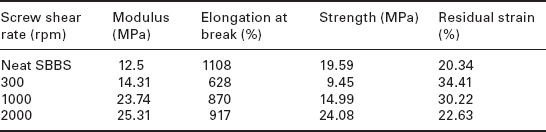
The use of layer-by-layer (LBL) assembly techniques has been demonstrated to have exceptional uniformity and versatility for constructing nanostructure composites with SWCNTs. Shim and Kotov (2005) introduced a fusion method for aligning SWCNTs during LBL assembly by taking advantage of air-water interfacial force, as shown in Fig. 1.3. Pressurized air flows over a wet surface with randomly absorbed SWCNTs so that the surface topography changes from random orientation to a unidirectional orientation. The ability of LBL to deposit one layer of SWCNT at a time can also be used to prepare criss-crossed SWCNT composites that are expected to have excellent mechanical properties with respect to several key parameters essential for both biomedical and space applications.
1.3 Schematic of SWCNT alignment via layer-by-layer assembly. Adapted from Shim and Kotov (2005).
Polar solvent exposure
Chen and Tao (2005) demonstrated the viability of using polar solvent exposure as a means of aligning CNTs. The polar solvent used, tetrahydrofuran, penetrates inside thermoplastic polyurethane, affecting the three-dimensional hydrogen-bonded structure in the hard segments and causing the arrested chain segments to relax and align during the swelling and moisture curing stage. This serves as the driving force for the self-assembly of the oriented nanotubes in the polymer. The solvent is then removed during the casting step.
Solution spinning
Solution spinning consists of dispersing nanotubes in a surfactant solution, recondensing the CNTs in the flow of the polymer solution to form a nanotube mesh and then collating this mesh to a nanotube fiber (Poulin et al., 2002). The flow-induced alignment leads to the formation of long ribbons that remain stable in the absence of flow. Control of the process parameters, such an injection rate, flow conditions and dimensions of the capillary tube, can be used to vary the diameter of the fabricated composite from a few microns up to 100 microns.
1.4.2 Transverse alignment
Transversely aligned CNT films currently focus mainly on electronic field emission (Fan et al., 1999; Fang et al., 2005). Self-oriented arrays of CNTs have been successfully grown by using CVD or PECVD methods. Integration of polymers to bind vertically aligned CNTs for microelectromechanical systems applications was explored by Fang et al. (2005), who used the technique to synthesize vertically aligned MWCNTs on silicon substrates. The small gaps between nanotubes were filled with Parylene dimers which were first vaporized at 150°C in a stainless steel chamber. The polymer vapor was mixed with methylene and introduced into a furnace at 680°C to yield a stable, monomeric diradical para-xylylene. Monomers were subsequently redirected into a room-temperature deposition chamber where they were simultaneously polymerized and absorbed on the MWCNTs. A simple etch step removes the polymer-reinforced nanotube forest from the underlying silicon substrate, forming a free-standing composite film.
1.5 Properties and characteristics
1.5.1 Mechanical properties – elastic modulus
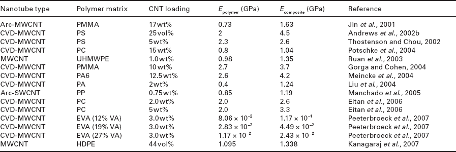
In most CNT/polymer composites, the increase in CNT composition enhances the mechanical properties. Ryan et al. (2007) reported that 0.1 vol% SWCNTs added to polyvinyl alcohol (PVOH) increased the elastic modulus over pure PVOH 300% and increased the tensile strength 200%. The same increase in modulus was observed for MWCNTs; however, the concentration of CNTs had to be increased to a higher level. The stiffness of the composites also increased due to the crystallization effects of PVOH around the CNT surface. For crystallization stiffening, smaller diameter CNTs provide enhanced crystallinity of PVOH. The variation in CNT wall structures, length, diameter, and chirality along with a large variety of host polymers makes correlating mechanical properties challenging. Additionally, as stated previously, the variety of processing techniques will also have a significant influence on the mechanical properties of the CNT/polymer nanocomposite. The elastic modulus resulting from a range of CNT/polymer composites categorized by processing technique is given in Table 1.4 (solution casting), Table 1.5 (melt mixing), and Table 1.6 (in situ polymerization). Several researchers have used theoretical models to predict CNT/polymer composite properties with increased CNT loading. Kanagaraj et al. (2007) used the Halpin– Tsai model and a modified series approach to predict the Young’s modulus of HDPE with increasing volume fraction of MWCNTs with good agreement. A comprehensive computational micromechanics analysis of high stiffness hollow fiber nanocomposites was performed by Hammerand et al. (2007) using finite element analysis wherein CNTs were modeled as isotropic hollow tubes or equivalent traversely isotropic effective solid cylinders with properties computed using a micromechanics-based composite cylinders method.
Table 1.4
Elastic modulus of polymers and nanocomposites processed via solvent-casting

Note: PS = polystyrene; PVA = polyvinyl acetate; PSBA = polystyrene butylacrylate; TPU = thermoplastic polyurethane.

1.5.2 Thermal properties
The thermal conductivity of carbon nanotubes can be as high as 3000 W/mK, about seven times higher than copper (385 W/mK) (Tang et al., 2003). However, the theoretical estimates for room-temperature thermal conductivity of an isolated SWCNT are significantly higher (6000 W/mK) (Biercuk et al., 2002). The addition of 1.0 wt% unpurified SWCNTs to epoxy resin showed a 70% increase in thermal conductivity at 40 K and an increase of 125% at room temperature, with a percolation threshold evident by a sharp onset in conductivity observed between just 0.1 and 0.2 wt% (Biercuk et al., 2002). Gonnet et al. (2006) determined the thermal conductivity for the aligned SWCNTs alone to be 42 W/mK at room temperature; however, upon introduction into an epoxy matrix, the thermal conductivity was seen to drop by nearly an order of magnitude, or equal to the level of a randomly oriented SWCNT in the epoxy due to molecular interactions between the SWCNTs and the epoxy which cause phonon scattering.
1.5.3 Electrical properties
The addition of CNTs to polymers significantly influences electrical properties of the polymer with additions as low as 0.1 vol% resulting in an 8–10 order of magnitude increase in conductivity, such as from 5 x 10⁻⁸ S/m for an unreinforced epoxy to 0.01 S/m for the CNT reinforced epoxy. In most cases the addition of CNTs results in the formation of a percolation network due to the presence of a three-dimensional path through the bulk resin. The addition of MWCNTs to polyethylene (PE) via twin-screw extrusion has been reported to improve the electrical conductivity from 10–20 to 10–4 S/cm with a percolation threshold of about 7.5 wt%, which is higher than that of most similar systems (McNally et al., 2005). A high concentration of CNJs is needed since PE encapsulates and isolates the MWCNTs, rendering them less effective at conduction. In this instance extrusion-induced CNT alignment reduces contact points between CNTs and it disrupts the three-dimensional percolation network. The addition of 1 wt% MWCNT to polypyrrole (PPy) increases the electrical conductivity by an order of magnitude, with the MWCNT/PPy composite exhibiting metallic electrical characteristics (current–voltage curve) (Yu et al., 2005). It should be noted that Park et al. (2006) reported that the conductivity can be controlled over six orders of magnitude by controlling the strength of the alignment electric field, with conductivities ranging from insulating levels of 10- 13 S/cm to conductive levels of 10–6 S/cm being attained in the alignment direction with 0.3 wt% SWCNT loading, which is lower than the percolation threshold for isotropic dispersion. Remarkably, the conductivity of the composite also increases perpendicular to the electric field alignment direction by about two orders of magnitude.
1.6 Future trends
The potential for CNTs as reinforcement and conductive media has not yet been fully realized. Mechanical properties of nanocomposites, for example, are still significantly lower than the theoretical estimates. Among the major challenges are the attainment of high quality dispersion, good alignment, and achieving a good interfacial bond between the CNT and the polymer. In addition there are still a number of challenges associated with maintaining the original length of the CNT through the process steps.
The establishment of strong interfacial adhesion between the nano-reinforcement and polymer matrix or an ordered interphase is important for maximizing the interfacial stress transfer capability of the nanocomposite. Nanotubes have been shown to nucleate polymer ciystallinity, creating an ordered CNT coating maximizing CNT/polymerbinding (Coleman et al., 2004). Strength increases due to morphological changes in the polymer matrix can be further explored through new processing techniques. Changes within the polymer structure, such as the addition of reactive functionalities or through the altering of solution pH, may be attractive options for further study. Peeterbroeck et al. (2004) found that increasing the content of polar vinyl acetate (VA) in ethylene vinyl acetate tends to slightly favor the dispersion of CNTs, whereas Grunlan et al. (2006) have proposed using a pH sensitive polymer to separate and distribute CNTs through the polymer matrix, such that at low pH the polymer is uncharged with a coiled structure, and as the pH is increased the polymer loses a proton and becomes negatively charged, causing extension of the polymer chains and repulsion, leading to dispersion of the graft CNTs.
Recent work has focused on using CNTs to improve the cohesive energy of polymer adhesives (Love et al., 2007). Property enhancements such as increased elongation and strain to failure with CNT loading are desired for adhesive applications. Changing the composition of CNTs in adhesive epoxy between composite laminates can also favorably influence the debonding and shear characteristics of the interface due to the large surface area and interlock between the CNTs and epoxy adhesive (Meguid and Sun, 2004). In the case of aerospace applications where specifically high levels of electrical conductivity are essential to avoid collection of electrostatic charges on control surfaces, the use of CNTs in adhesives can be a major advantage, even over the use of lower-cost carbon black, since the addition of CNTs actually enhances adhesive response.
The addition of CNTs to polymeric materials has been shown thus far to improve mechanical, thermal, and electrical properties. In most instances only a small amount of CNTs are needed to greatly increase properties such as modulus for elastomers and thermoplastics, electrical properties of polymers such as HDPE, etc. The addition of CNTs into natural rubber consumes less energy than incorporating carbon black into natural rubber (Sui et al., 2007), indicating advantages even in energy consumption. The use of conductive CNTs in combination with conductive polymer matrices such as polyaniline and polypyrrole could lead to the development of materials that integrate functionalities such as structural response with sensor function. Small amounts of CNTs added to PA6 are known to enhance the fire retardance of polymeric systems through an increased melt viscosity that prevents dripping and flowing at or near fire conditions. In addition, the ability of the CNTs to form a percolation network allows faster and more efficient dissipation of heat, thereby also enhancing flame retardancy. Alternative energy sources, relying on high conductivity and charge capacitance capabilities, open the door to new-generation composite electrode materials, proton exchange membranes for fuel cells, and solar cells for photovoltaic devices. There is significant promise that the incorporation of CNTs into traditional composites would further enhance functionality, compression and shear response, and even through-thickness characteristics. However, the primary challenges are still those related to processing, initiating at the level of processing of the CNTs themselves at scale, through their dispersion in melts and solvents and then their alignment in actual products at levels and with the functionality desired. The solution of the challenges posed by these issues will undoubtedly open new vistas for the development of new tailored materials designed for specific applications.
1.7 References
Andrews, R., Weisenberger, M.C. Current Opinion in Solid State and Materials Science. 2004; 8:31.
Andrews, R., Jacques, D., Minot, M., Rantell, T. Macromolecular Materials and Engineering. 2002; 287:395.
Andrews, R., Jacques, D., Qian, D., Rantell, T. Acc. Chem. Res.. 2002; 35:1008.
Bal, S., Samal, S.S. Bulletin of Materials Science. 2007; 30:379.
Barraza, H.J., Pompeo, F., O’Rear, E.A., Resasco, D.E. Nano Lett. 2002; 2:797.
Biercuk, M.J., Llaguno, M.C., Radosavljevic, M., Hyun, J.K., Johnson, A.T., et al. Applied Physics Letters. 2002; 80:2767.
Blond, D., Barron, V., Ruether, M., Ryan, K.P., Nicolosi, V., et al. Advanced Functional Materials. 2006; 16:1608.
Bubert, H., Haiber, S., Brandl, W., Marginean, G., Heintze, M., et al. Diamond and Related Materials. 2003; 12:811.
Cadek, M., Coleman, J.N., Barron, V., Hedicke, K., Blau, W.J. Applied Physics Letters. 2002; 81:5123.
Cadek, M., Coleman, J.N., Ryan, K.P., Nicolosi, V., Bister, G., et al. Nano Lett. 2004; 4:353.
Chen, Q., Xu, R., Yu, D. Polymer. 2006; 47:7711.
Chen, W., Tao, X. Macromolecular Rapid Communications. 2005; 26:1763.
Chen, X.Q., Saito, T., Yamada, H., Matsushige, K. Applied Physics Letters. 2001; 78:3714.
Coleman, J.N., Cadek, M., Blake, R., Nicolosi, V., Ryan, K.P., et al. Advanced Functional Materials. 2004; 14:791.
Coleman, J.N., Khan, U., Blau, W.J., Gun’ko, Y.K. Carbon. 2006; 44:1624.
Cooper, C.A., Ravich, D., Lips, D., Mayer, J., Wagner, H. Composites Science and Technology. 2002; 62:1105.
Dai, L., Patil, A., Gong, X., Guo, Z., Liu, L., et al. Chem Phys Chem. 2003; 4:1150.
Dalmas, F., Chazeau, L., Gauthier, C., Masenelli-Varlot, K., Dendievel, R., et al. Journal of Polymer Science Part B: Polymer Physics. 2005; 43:1186.
Deck, C.P., Vecchio, K. Carbon 44. 2006; 267.
Dondero, W.E., Gorga, R.E. Journal of Polymer Science Part B: Polymer Physics. 2006; 44:864.
Dufresne, A., Paillet, M., Putaux, J.L., Canet, R., Carmona, F., et al. Journal of Materials Science. 2002; 37:3915.
Eitan, A., Fisher, F.T., Andrews, R., Brinson, L.C., Schadler, L.S. Composites Science and Technology. 2006; 66:1162.
Esawi, A.M.K., Farag, M.M. Materials & Design. 2007; 28:2394.
Fan, S., Chapline, M.G., Franklin, N.R., Tombler, T.W., Cassell, A.M., Dai, H. Science. 1999; 283:512.
Fang, W., Chu, H.Y., Hsu, W.K., Cheng, T.W., Tai, N.H. Advanced Materials. 2005; 17:2987.
Fidelus, J.D., Wiesel, E., Gojny, F.H., Schulte, K., Wagner, H.D. Composites Part A: Applied Science and Manufacturing. 2005; 36:1555.
Foster, J., Singamaneni, S., Kattumenu, R., Bliznyuk, V. Journal of Colloid and Interface Science. 2005; 287:167.
Gao, J., Itkis, M.E., Yu, A., Bekyarova, E., Zhao, B., et al. J. Am. Chem. Soc. 2005; 127:3847.
Gibson, R.F., Ayorinde, E.O., Wen, Y.F. Composites Science and Technology. 2007; 67:1.
Gojny, F.H., Schulte, K. Composites Science and Technology. 2004; 64:2303.
Gong, X., Liu, J., Baskaran, S., Voise, R.D., Young, J.S. Chem. Mater.. 2000; 12:1049.
Gonnet, P., Liang, Z., Choi, E.S., Kadambala, R.S., Zhang, C., et al. Current Applied Physics. 2006; 6:119.
Gorga, R.E., Cohen, R.E. Journal of Polymer Science Part B: Polymer Physics. 2004; 42:2690.
Gorga, R.E., Lau, K.K.S., Gleason, K.K., Cohen, R.E. Journal of Applied Polymer Science. 2006; 102:1413.
Grunlan, J.C., Liu, L., Kim, Y.S. Nano Lett. 2006; 6:911.
Guo, J., Li, Y., Wu, S., Li, W. Nanotechnology. 2005; 16:2385.
Haggenmueller, R., Gommans, H.H., Rinzler, A.G., Fischer, J.E., Winey, K.I. Chemical Physics Letters. 2000; 330:219.
Hammerand, D.C., Seidel, G.D., Lagoudas, D.C. Mechanics of Advanced Materials and Structures. 2007; 14:277.
Hassanien, A., Gao, M., Tokumoto, M., Dai, L. Chemical Physics Letters. 2001; 342:479.
Hong, C.E., Lee, J.H., Kalappa, P., Advani, S.G. Composites Science and Technology. 2007; 67:1027.
Hussain, F., Hojjati, M., Okamoto, M., Gorga, R.E. Journal of Composite Materials. 2006; 40:1511.
Hwang, G.L., Shieh, K.T., Hwang, K.C. Advanced Functional Materials. 2004; 14:487.
Iijima, S. Nature. 1991; 354:56.
Jia, Z., Wang, Z., Xu, C., Liang, J., Wei, B., et al. Materials Science and Engineering: A. 1999; 271:395.
Jin, S.H., Park, Y.-B., Yoon, K.H. Composites Science and Technology. 2007; 67:3434.
Jin, Z., Pramoda, K.P., Xu, G., Goh, S.H. Chemical Physics Letters. 2001; 337:43.
Kanagaraj, S., Varanda, F.R., Zhil’tsova, T.V., Oliveira, M.S.A., Simoes, J.A.O. Composites Science and Technology. 2007; 67:3071.
Khan, U., Ryan, K.P., Blau, W.J., Coleman, J.N. Composites Science and Technology. 2007; 67:3158.
Kimura, T., Ago, H., Tobita, M., Ohshima, S., Kyotani, M., et al. Advanced Materials. 2002; 14:1380.
Konya, Z., Vesselenyi, I., Niesz, K., Kukovecz, A., Demortier, A., et al. Chemical Physics Letters. 2002; 360:429.
Kumar, S., Dang, T.D., Arnold, F.E., Bhattacharyya, A.R., Min, B.G., et al. Macromolecules. 2002; 35:9039.
Kwon, J., Kim, H. Journal of Polymer Science Part A: Polymer Chemistry. 2005; 43:3973.
Lau, K.T., Gu, C., Hui, D. Composites Part B: Engineering. 2006; 37:425.
Li, S.-N., Li, Z.-M., Yang, M.-B., Hu, Z.-Q., Xu, X.-B., et al. Materials Letters. 2004; 58:3967.
Li, Y., Shimizu, H. Polymer. 2007; 48:2203.
Liu, T.X., Phang, I.Y., Shen, L., Chow, S.Y., Zhang, W.D. Macromolecules. 2004; 37:7214.
Love, C.T., Karbhari, V.M. unpublished results. . 2007.
Love, C.T., Gapin, A., Karbhari, V.M. Nanopolymers 2007; [Rapra, Berlin, Germany, 2007].
Lozano, K., Barrera, E.V. Journal of Applied Polymer Science. 2001; 79:125.
Manchado, M.A.L., Valentini, L., Biagiotti, J., Kenny, J.M. Carbon. 2005; 43:1499.
Martin, C.A., Sandler, J.K.W., Windle, A.H., Schwarz, M.K., Bauhofer, W., et al. Polymer. 2005; 46:877.
McNally, T., Potschke, P., Halley, P., Murphy, M., Martin, D., et al. Polymer. 2005; 46:8222.
Meguid, S.A., Sun, Y. Materials & Design. 2004; 25:289.
Meincke, O., Kaempfer, D., Weickmann, H., Friedrich, C., Vathauer, M., et al. Polymer. 2004; 45:739.
Moniruzzaman, M., Winey, K.I. Macromolecules. 2006; 39:5194.
Odegard, M., Frankland, S.J.V., Gates, T.S. American Institute of Aeronautics and Astronautics Journal. 2005; 43:1828.
Park, C., Ounaies, Z., Watson, K.A., Crooks, R.E., Smith, J., et al. Chemical Physics Letters. 2002; 364:303.
Park, C., Wilkinson, J., Banda, S., Ounaies, Z., Wise, K.E., et al. Journal of Polymer Science Part B: Polymer Physics. 2006; 44:1751.
Park, S.J., Cho, M.S., Lim, S.T., Choi, H.J., Jhon, M.S. Macromolecular Rapid Communications. 2003; 24:1070.
Peeterbroeck, S., Breugelmans, L., Alexandre, M., BNagy, C.J., Viville, P., et al. The influence of the matrix polarity on the morphology and properties of ethylene vinyl acetate copolymers-carbon nanotube nanocomposites. Composites Science and Technology. 67, 2004.
Peeterbroeck, S., Breugelmans, L., Alexandre, M., Nagy, J.B., Viville, P., et al. Composites Science and Technology. 2007; 67:1659.
Peng, M., Li, D., Chen, Y., Zheng, Q. Macromolecular Rapid Communications. 2006; 27:859.
Potschke, P., Bhattacharyya, A.R., Janke, A. European Polymer Journal. 2004; 40:137.
Poulin, P., Vigolo, B., Launois, P. Carbon. 2002; 40:1741.
Probst, O., Moore, E.M., Resasco, D.E., Grady, B.P. Polymer. 2004; 45:4437.
Putz, K.W., Mitchell, C.A., Krishnamoorti, R., Green, P.F. Journal of Polymer Science Part B: Polymer Physics. 2004; 42:2286.
Qian, D., Dickey, E.C., Andrews, R., Rantell, T. Applied Physics Letters. 2000; 76:2868.
Rakov, E.G., Carbon Nanomaterials. Gogotsi, Y. Taylor & Francis Group, Boca Raton, FL, 2006:77.
Ramanathan, T., Fisher, F.T., Ruoff, R.S., Brinson, L.C. Chem. Mater. 2005; 17:1290.
Regev, O., ElKati, P.N.B., Loos, J., Koning, C.E. Advanced Materials. 2004; 16:248.
Rinzler, A.G., Liu, J., Dai, H., Nikolaev, P., Huffman, C.B., et al. Applied Physics A: Materials Science & Processing. 1998; 67:29.
Ruan, S.L., Gao, P., Yang, X.G., Yu, T.X. Polymer. 2003; 44:5643.
Ryan, K.P., Cadek, M., Nicolosi, V., Blond, D., Ruether, M., et al. Composites Science and Technology. 2007; 67:1640.
Safadi, B., Andrews, R., Grulke, E.A. Journal of Applied Polymer Science. 2002; 84:2660.
Scott, C.D., Arepalli, S., Nikolaev, P., Smalley, R.E. Applied Physics A: Materials Science & Processing. 2001; 72:573.
See, C.H., Harris, A.T. Ind. Eng. Chem. Res. 2007; 46:997.
Shaffer, M.S.P., Windle, A.H. Advanced Materials. 1999; 11:937.
Shanmugharaj, A.M., Bae, J.H., Lee, K.Y., Noh, W.H., Lee, S.H., et al. Composites Science and Technology. 2007; 67:1813.
Shi, D., He, P., Lian, J., Chaud, X., Bud’ko, S.L., et al. Journal of Applied Physics. 2005; 97:064312.
Shim, B., Kotov, N.A. Langmuir. 2005; 21:9381.
Sui, G., Zhong, W., Yang, X., Zhao, S. Macromolecular Materials and Engineering. 2007; 292:1020.
Tang, W., Santare, M.H., Advani, S.G. Carbon. 2003; 41:2779.
Thostenson, E.T., Chou, T.W. Journal of Physics D: Applied Physics. 2002; L77.
Thostenson, E.T., Ren, Z.F., Chou, T.W. Composites Science and Technology. 2001; 61:1899.
Thostenson, E.T., Li, C., Chou, T.W. Composites Science and Technology. 2005; 65:491.
Vandervorst, P., Lei, C.H., Lin, Y., Dupont, O., Dalton, A.B., et al. Progress in Organic Coatings. 2006; 57:91.
Vast, L., Philippin, G., Destrée, A., Moreau, N., Fonseca, A., et al. Nanotechnology. 2004; 15:781.
Velasco-Santos, C., Martinez-Hernandez, A.L., Fisher, F., Ruoff, R., Castano, V.M. Journal of Physics D: Applied Physics. 2003; 36:1423.
Velasco-Santos, C., Martinez-Hernandez, A.L., Fisher, F.T., Ruoff, R., Castano, V.M. Chem. Mater.. 2003; 15:4470.
Wanekaya, A.K., Lei, Y., Bekyarova, E., Chen, W., Haddon, R., et al. Electroanalysis. 2006; 18:1047.
Wang, C.G., Guo, Z.X., Fu, S., Wu, W., Zhu, D. Progress in Polymer Science. 2004; 29:1079.
Wang, T., Lei, C.H., Dalton, A.B., Creton, C., Lin, Y., et al. Advanced Materials. 2006; 18:2730.
Wood, J.R., Zhao, Q., Wagner, H.D. Composites Part A: Applied Science and Manufacturing. 2001; 32:391.
Xia, H., Wang, Q., Qiu, G. Chem. Mater.. 2003; 15:3879.
Xia, H., Wang, Q., Li, K., Hu, G.H. Journal of Applied Polymer Science. 2004; 93:378.
Xia, H., Qiu, G., Wang, Q. Journal of Applied Polymer Science. 2006; 100:3123.
Xie, X.L., Mai, Y.W., Zhou, X.P. Materials Science and Engineering: R: Reports. 2005; 49:89.
Xu, Y., Higgins, B., Brittain, W.J. Polymer. 2005; 46:799.
Yamamoto, K., Akita, S., Nakayama, Y. Japanese Journal of Applied Physics. 1996; 35:917.
Yu, Y., Ouyang, C., Gao, Y., Si, Z., Chen, W., et al. Journal of Polymer Science Part A: Polymer Chemistry. 2005; 43:6105.
Zhang, Q., Lippits, D.R., Rastogi, S. Macromolecules. 2006; 39:658.
Zhu, J., Peng, H., Rodriguez-Macias, F., Margrave, J.L., Khabashesku, V.N., et al. Advanced Functional Materials. 2006; 14:643.
☆Note: This chapter is a revised and updated version of Chapter 19 ‘Processing of carbon nanotubes and carbon nanotube based nanocomposites’ by V. M. Karbhari and C. T. Love, also published in Advances in polymer processing: From macro to nano scales, ed. S. Thomas and Y. Weimin, Woodhead Publishing Limited, published 2009, ISBN: 978-1-84569-396-1.