4
Technical and Operational Scenarios
As discussed in Chapters 2 and 3, describing “cyber” is a challenge, from evaluating business impact to modeling the technical underpinnings that compose the backbone of our critical systems. For example, Mandiant (FireEye 2017) recently reported malware detection and mitigation numbers:
“Fortunately, we’re seeing that organizations are becoming better at identifying breaches. The global median time from compromise to discovery has dropped significantly from 146 days in 2015 to 99 days in 2016, but it is still not good enough. As we noted in M‐Trends 2016, a Mandiant Red Team can obtain access to domain administrator credentials within roughly three days of gaining initial access to an environment, so 99 days is still 96 days too long.”
Developing technical and operational scenarios is an activity that spans from policy to technical implementation in determining the controls and indicators used in proper system evaluation. A popular approach for performing high‐level evaluation includes threat modeling, which provides opportunities for future scenario and Course of Action (COA) use cases. For example, PASTA™ (Velez and Morana 2015) (Table 4.1) provides an overall methodology for threat evaluation that could serve M&S as an overall approach.
Table 4.1 Stages of Process for Attack Simulation and Threat Analysis (PASTA) threat modeling methodology.
| Define objective |
|
| Define technical scope |
|
| Application decomposition |
|
| Threat analyses |
|
| Vulnerability and weakness mapping |
|
| Attack modeling |
|
| Risk and impact analysis |
|
Table 4.1’s PASTA, with similarities to the NIST SP 800 approach (Chapter 2, Table 2.1), is an example of a high‐level analysis approach for developing future, baseline, scenarios, and subsequent Courses of Action (COAs). Leveraging end‐to‐end processes for system evaluation will be aided by system decompositions for follow‐on evaluation. The ARMOUR Framework (DRDC (Canada) 2013a, b) provides example technical and operational scenarios with the aim of supporting an overall cyber framework.
4.1 Scenario Development
Protective cyber scenarios take a variety of forms. For example, Table 4.2 provides a set of potentially life‐threatening examples where cyber operators likely had minimal notice to determine a real‐time COA.
Table 4.2 Operational examples.
| Date | Scenario example |
| April 2016 until at least February 2017 | Operation Electric Powder (ClearSky Research Team 2017)
Attempt to penetrate Israel Electric Company (IEC) |
| 2014 | German Steel Mill Cyber Attack (Lee et al. 2014) with confirmed physical damage |
| February 2013 to April 2014 | Dragonfly (Symantec 2014): Cyber espionage attacks Against energy suppliers
A newer approach used by the attackers involves compromising the update site for several industrial control system (ICS) software producers. They then bundle Backdoor. Oldrea with a legitimate update of the affected software. To date, three ICS software producers are known to have been compromised. The Dragonfly attackers used hacked websites to host command‐and‐control (C&C) software. |
| August to September, 2013 | Rye Dam (New York) (NEWSWEEK 2016) – Threat actors accessed the Supervisory Control and Data Acquisition system, which connects to the Internet through a cellular modem – after allegedly obtaining water‐level and temperature information, could have operated the floodgate remotely if it had been operating at the time. |
As shown in Table 4.2, cyber scenarios occur over a period of time, usually in stages, including both technical and operational elements in the detect–mitigate–recover phases of a resilience scenario. To assist in technical evaluation and operator training, Canada’s ARMOUR (DRDC (Canada) 2014a, b) cyber technical demonstrator (TD) developed technology‐specific approaches, including “proactive” and “reactive” scenarios, as shown in its concept of operations (CONOPS) (Table 4.3).
Table 4.3 Proactive and reactive ARMOUR scenarios (DRDC (Canada) 2014a, b).
| ARMOUR scenario | Description |
| Proactive |
|
| Reactive | Once an asset has been identified with an exploited vulnerability, ARMOUR provides the operator with the capability to identify potential attack paths or attack vectors to other assets that may have been exposed. This attack path can provide insight into other similarly affected hosts and can also indicate where this exploit, or a related exploit, could be used to gain access to another network connected host in the topology. With this ability to uncover the potential attack vectors, ARMOUR provides the operator with a complete understanding of the potential capabilities that the observed exploit could provide to the attacker. Once the attack graph is generated, COAs are provided to the operator to resolve the vulnerabilities thereby mitigating the propagation of the attack any further. Simulation of the COAs demonstrates to the operator the impact of implementing the risk mitigation. The COAs implemented could include removing the vulnerability from the attack point (initially infected asset) and/or removing the vulnerability from assets further down in the attack path. |
As shown in Table 4.3, proactive scenarios are used to evaluate how the network responds to anomalies, or time to detect (Tdetect) anomalous devices and configuration changes. These are sometimes called technical scenarios; similar to what is evaluated via critical security controls (CSCs). Reactive scenarios, on the other hand, are usually called operational simulations, often training‐focused, and are used to perform standard Disaster Recovery/Continuity of Operations (DR/COOP) enterprise evaluations.
Scenarios, therefore, are inherently context‐dependent, in that applying CSCs should protect a system from obvious threats, with training to maintain both awareness and responsiveness should an attacker gain access.
4.1.1 Technical Scenarios and Critical Security Controls (CSCs)
Technical scenarios primarily deal with network anomalies. As a preventive example, the Australian Signal Directorate’s “Top 4” is popular for its reported ability to prevent 85% of cyberattacks (Defense). Similar to the ASD opposition force is the NIST 800‐53‐based CSCs.
A clear advantage to using operational scenarios, as shown in Table 4.3, is that the evaluations are in numbers (number of nefarious nodes, time to respond, etc.). Operational scenarios are more challenging with the story line needing to be developed for the specific threat of interest.
4.1.2 ARMOUR Operational Scenarios (Canada)
ARMOUR (DRDC (Canada) 2013a, b, 2014a, b) was a Canadian effort to develop an architecture‐based framework, leveraging cyber models, to build a test bed for training and technology evaluations. The ARMOUR framework performs operational scenarios using the same underlying technical architecture, changing the focus from measurable network goals to more human‐oriented evaluations (Table 4.4).
Table 4.4 ARMOUR operational scenarios (DRDC (Canada) 2014a, b).
| Scenario | Description |
| User Identification and Authentication | The User Identification and Authentication operation represents the system interactions between services/modules during an operator login to the data presentation framework. |
| User Data Request | The User Data Request Operational Scenario describes the system and service interactions and data flows for the situation where a user opens a presentation view and makes a request to view stored data. |
| Network Data Collection and Presentation | The Network Data Collection and Presentation scenario depicts an information flow for the collection, normalization, validation, storage, and presentation of network information from a data source. The contextual operation represents a generic flow of data and can be applied to virtually any data source (each data source will have at least one individual data source connector). |
| Reaction to Events | In this scenario, a link between a host and router/switch will become saturated and will require the user’s intervention. The user will select the intervention widget and be able to “drag n drop” an alert from the Alerts component to the intervention component. The intervention component will be populated with relevant remediation methods based on the alert type being displayed. Upon selection of an intervention method, the system will generate a rule request to fix the issue. |
As shown in Table 4.4, ARMOUR scenarios are practical, mirroring actual network events that are easily duplicated on real or emulated networks. In addition, operational scenarios often involve a story line, usually from a real incident (Table 4.2), that is generalized to a training objective (Kick 2014). As shown in Figure 4.1, cyber events are developed with both the event goals and the estimated environment in mind.
Each of the Scenarios in Table 4.4 will require a structured process to determine how well the team did in defending their system. Figure 4.1 provides a standardized approach for conducting cyber events for security evaluation.
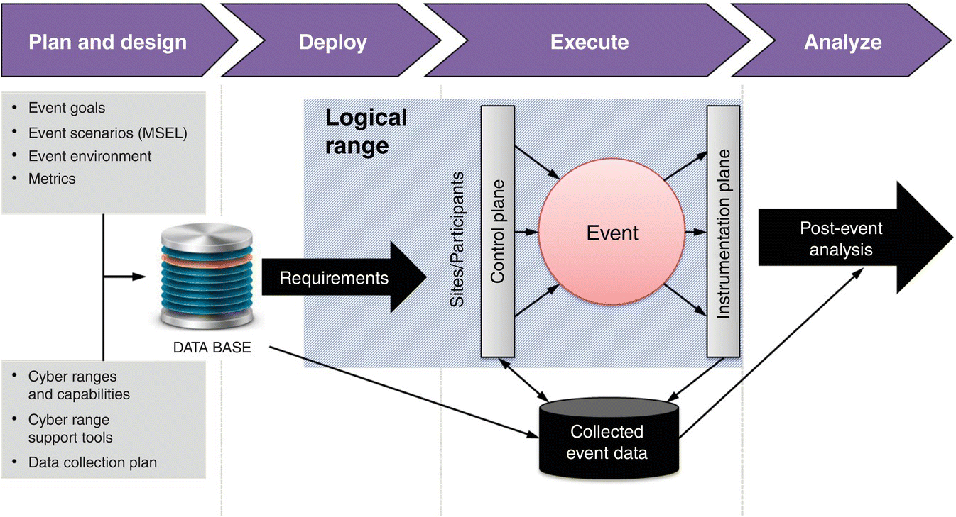
Figure 4.1 Cyber‐range event process overview.
Figure 4.1 (Damodaran and Couretas 2015) provides an example exercise flow, often used with a scenario designed to emulate real‐world events; e.g. operational examples for ICSs shown in Table 4.2.
4.2 Cyber System Description for M&S
Risk evaluations provide a system overview, and potential baseline, for a system’s estimated susceptibility to known cyber issues. Generalizing on these assessments, usually static evaluations, in developing a repeatable and valid cyber description for M&S, is a challenge. Many descriptions attempt to bridge current cyber’s Information Assurance (IA) foundations to provide approaches that span from IA to M&S.
4.2.1 State Diagram Models/Scenarios of Cyberattacks
One approach (Leversage and Byres 2007) is to (i) decompose the network into its respective sections and (ii) use CIA language to describe the course of an attack (Figure 4.2).

Figure 4.2 Attack path model using “CIA” system states.
Figure 4.2’s method provides an approach for answering strategic questions. For example, the likelihood of succeeding along one of the CIA paths, the time it takes, or any associated operational costs to improve threat path defense.
4.2.2 McCumber Model
While Figure 4.2 provides a path model for a cyberattack, it is a natural next step to ask for more detail concerning the underlying system and its security posture. The McCumber model, well known to information security researchers, is reviewed here for cyber M&S scenario development. In addition to describing cyber security processes, the McCumber model “protects” the confidentiality, integrity, and availability (CIA) of mission systems “during” data storage/processing/transmission, while “using” technology/people/procedure and policy (Figure 4.3). From an M&S perspective, the McCumber model provides a conceptual approach to explore the impact of cyber activity on technology (i.e. a physical system) as well as people (i.e. behavior). In modeling a particular cyber phenomenon, the model captures all the parameters that must be addressed within the M&S environment. For a technology, the effect must be adequately modeled to represent its storage and processing capability during a transmission as well as all activities taken to protect the data from cyber activities.

Figure 4.3 McCumber model.
The functional aspects of the McCumber model dovetail with the more structured requirements of M&S, generally, and scenario development, more specifically. An extension to the McCumber model includes:
- Authentication: guaranty vis‐à‐vis the destination that the information’s origin/content is confirmed and certified as such. Each party to an exchange of information on both sides should be able to guarantee the identity of the other parties involved.
- Non‐repudiation: guaranty vis‐à‐vis the origin, that the information reached the destination intact and unaltered. It is a guaranty that the information has been delivered to the destination, preventing the recipient from later denying receiving it. Non‐repudiation protects against counterfeit information.
In addition to providing data provenance, the McCumber Cube provides a straightforward approach for looking at data, at rest or in transmission, to add a layer of technical detail to the IA CIA evaluation (Figure 4.2). Modeling both forms of data is of interest for scenario development.
4.2.3 Military Activity and Cyber Effects (MACE) Taxonomy
In addition to the McCumber model’s more detailed description of the cyber terrain, we further narrow the scope of our cyber scenario development efforts with the Military Activity and Cyber Effects (MACE) taxonomy (Bernier 2015), which consists of six main categories:
- Attack Types: covers the most significant types of cyber‐attacks.
- Levels of Access: describes the different levels of access to the targeted system or network required to launch a type of attack.
- Attack Vectors: includes the methods and tools used to infiltrate computers and install malicious software.
- Adversary Types: identifies the various types of cyber attackers.
- Cyber Effects: describes the effects that can be produced in the cyber environment by employing the various cyber‐attacks.
- Military Activities: includes the military effects that can be produced in the cyber environment.
In addition, the MACE taxonomy provides a means for cross‐referencing cyber effects with military activities to provide an overall impact estimate:
Leveraging MACE, we develop attack types, with the goal of looking at their corresponding information security effects (Figure 4.4).
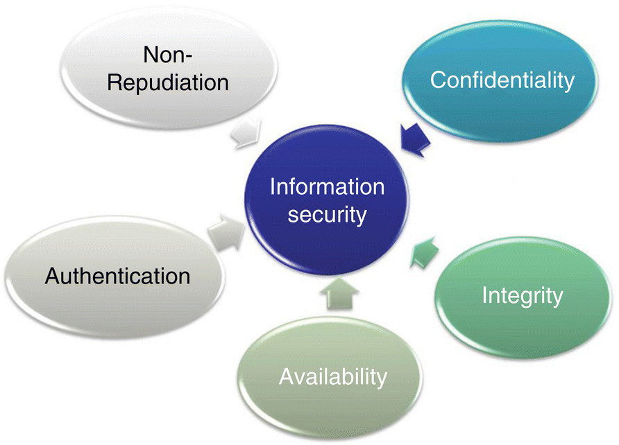
Figure 4.4 Components of information security.
From the M&S perspective, these six categories should be considered. In particular, the cyber effect combined with the military activity represents the impact a particular cyber threat may have on an operation. Table 4.5 captures the relationship between various cyber effects and military activities for consideration during scenario development.
While MACE provides an initial approach for providing a cyber/military effects description, the Cyber Operational Architecture Training System (COATS) leveraged actual range effects to inform cyber training simulation.
Table 4.5 Cyber effects and military activities.
| Cyber effects and military activities | Description |
| Cyber effects |
|
| Military activities |
|
4.2.4 Cyber Operational Architecture Training System (COATS) Scenarios
COATS explores methods for using M&S to support training. The COATS program demonstrated several interoperability approaches for supporting M&S to include the exploring of extensions to data models to specifically model cyber effects. The objects of the COATS program are to:
- Enable synchronous execution of traditional training and cyber operations.
- Accurately model and simulate traditional training and cyber events/interactions.
- Draft interoperability guidelines for cyber‐traditional federation.
- Distribute realistic cyber effects to the entire staff.
4.2.4.1 Cyber M&S Operational View Architecture (OV‐1) (COATS Example)
For all the scenarios described, the operational architecture remains the same; the cyber range provides a safe environment to deploy a cyber operation. The key parameters representing the cyber operation are identified, captured, and represented in the model. The cyber effect is then transitioned from the cyber range, to a training environment, to emulate an actual cyberattack on an operator’s workstation. This general approach has proven effective for training operators in identifying and responding to cyber activities. Figure 4.5 depicts the generalized OV‐1.

Figure 4.5 Cyber Operational Architecture Training System (COATS) (OV‐1).
As shown in Figure 4.5, a cyber range environment is used for mission operator training. We will next provide a few examples that leverage several scenarios from the COATS (Wells and Bryan 2015) project.
COATS was evaluated via Table 4.6’s four scenarios, which presented both cyber and mission effects. Both the full motion video degradation and the command and control examples dealt with packet loss (i.e. Integrity in the CIA triad) in simulating performance deterioration, from a transmission and process standpoint, respectively. In addition, the SYN Flood (i.e. denial of service attack) and data diddling examples (i.e. critical asset blue screen of death) were both processing phase attacks, requiring more refined information (i.e. McCumber Cube description) on the part of the attacker.
Table 4.6 Cyber Operational Architecture Training System (COATS) scenarios.
| Scenario | Description |
| Computer Network Attack (CNA) | Live red CNA against virtual blue systems to demonstrate virtual host degradation effects on live operator workstations. |
| Node Attack | Constructive red kinetic attack on a constructive blue communications facility to demonstrate C2 disruption effects on live operator workstations. |
| Distributed Denial of Service | Live red CNA on virtual blue systems to demonstrate virtual full‐motion video degradation effects on live operator workstations. |
| Threat Network Degradation | Live blue CNA on virtual red networks to demonstrate constructive system degradation on constructive red systems. |
One of the key takeaways of Table 4.6’s four scenarios is the applicability of the McCumber model to cyber M&S scenario development. The McCumber model provides clarity on what is being protected (e.g. CIA), when (transmission, storage, processing) and how (technology/people/procedure). Using this approach provides a clear language for how and why scenarios are constructed for cyber modeling and simulation, clarifying some of the uncertainty now found in applying cyber to standard training models.
Leveraging Table 4.5’s definitions, one example is of mapping the COATS (Wells and Bryan 2015; Morse et al. 2014a, b) vignettes to Table 4.7’s cyber effects; along with attack examples and McCumber Cube (Figure 4.3) descriptions of how the attack may occur.
Table 4.7 Cyber effects and attack type examples.
| Military activity | Cyber effect | Attack type | System performance effect | Using | During |
| Deny (degrade, disrupt, destory) | Interruption (Availability) | Full Motion Video (FMV) degradation | Latency, jitter, packet loss | Technology | Transmission |
| Degradation (Availability) | Interrupt supply chain and/or force flow | ICS, Location fidelity | All | Transmission, Storage | |
| Interruption (Availability) | System Shutdown | Memory Utilization | Technology P&P | Processing | |
| Manipulate | Modification (Integrity, Authenticity | Reduce Situational Awareness, interrupt/delay C2 | Packet loss | Technology | Transmission |
The Attack Types represent the cyber effect modeled in each scenario and the two columns, “Using” and “During” detail the systems (technology), people, and timing of the effect in the scenario. Cyber effects in Table 4.7’s first column are the four specific vignettes developed by the COATS program. While the MACE and McCumber approaches capture cyber effects and system operations in Table 4.7, accounting for CIA in standard IA terminology, constructive modeling will likely occur at a lower level of description.
4.3 Modeling and Simulation Hierarchy – Strategic Decision Making and Procurement Risk Evaluation
As introduced by the COATS figure (Figure 4.5), understanding the combined technical (e.g. network anomaly) to mission effect is one of the primary goals of cyber M&S thus far. Rowe et al. (2017) provides a depiction of how M&S might support strategic decision making in Figure 4.6.
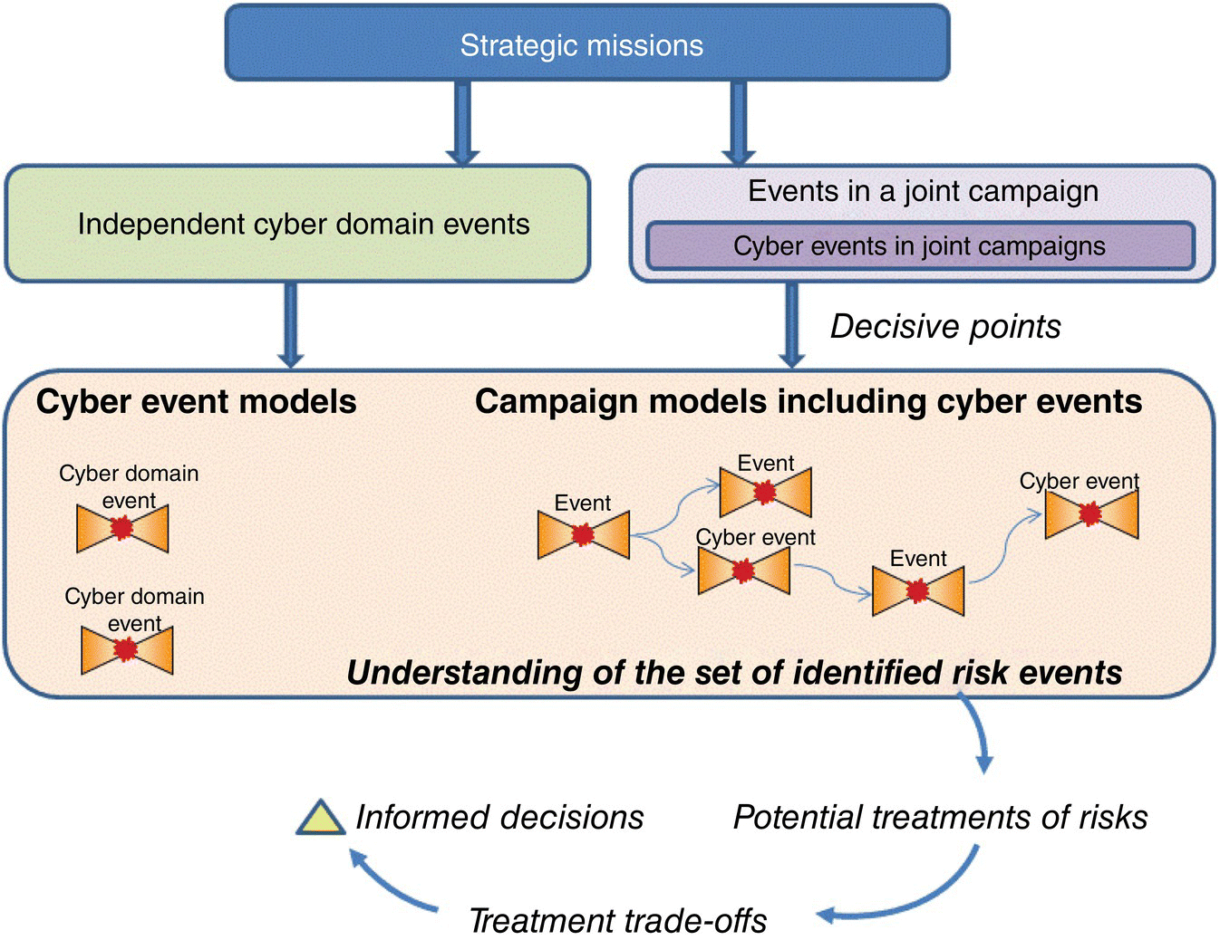
Figure 4.6 Cyber effects and mission evaluation Rowe et al. (2017) – http://journals.sagepub.com/doi/abs/10.1177/1548512917707077?journalCode=dmsa
While the COATS diagram (Figure 4.5) provides the mechanics for incorporating cyber effects into training simulations, Figure 4.6 works to clarify the taxonomy of events, including cyber, that help with developing decision points in both cyber and campaign models. In addition, Figure 4.6 leverages the risk bow‐tie (Figure 4.7) when considering preventive and remediation control applications.

Figure 4.7 Risk bow‐tie (Nunes‐Vaz et al. 2011, 2014).
Figures 4.6 and 4.7 combine, in the form of the Strategic Risk Framework, to provide the top layer of Figure 4.8’s hierarchy. In addition, Figure 4.8 provides examples of controls and current models at each layer of the hierarchy; the overall goal of the construct is to provide a Strategic Cyber Decision making capability.
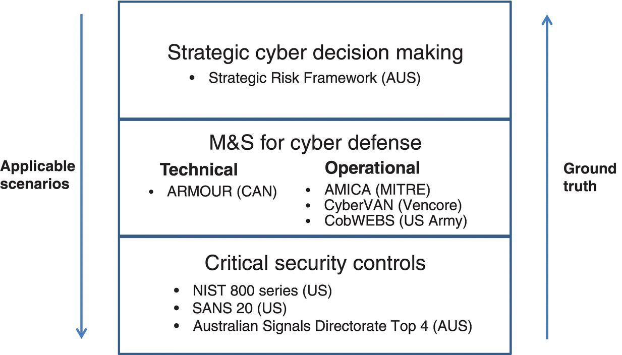
Figure 4.8 Strategic cyber decision making – leveraging M&S tools and cyber controls. US Army’s CobWEBS (Marshall 2015) and Vencore Corporation’s CyberVAN are models currently used to evaluate defense concepts.
As shown in Figure 4.8, cyber evaluation includes scenarios that span from strategy/investment to the operational (i.e. system architecture) and lower‐level control implementation; leveraging both technology and training. Figure 4.8 provides the Australian approach for prioritizing cyber investment (Rowe et al. 2017), exemplifying a strategic cyber decision‐making overview, used here for investment evaluation, leveraging the standard CSCs used by IT professionals to secure the network. M&S for cyber defense describes the frameworks (e.g. Canada’s ARMOUR) and operational models (e.g. MITRE’s AMICA [Noel et al. 2015]).
4.4 Conclusions
Figure 4.8’s example of performing strategic portfolio evaluation leveraging the correct underlying descriptive and prescriptive models is one of the end states for how cyber M&S will serve the community. This culminating example, while at a strategic investment level, could also provide operational data via scenarios (Table 4.2, Figures 4.5 and 4.6) for technical and operational evaluations via the estimated performance of the underlying system. In addition, this approach spans from preventive and reactive, through technical/operational modeling, to strategic risk evaluation for an enterprise‐level cyber system.
4.5 Questions
- 1 Name some common approaches for describing Figure 4.2’s attack path model. For example,
- A Bayesian approaches
- B Markov Modeling
- C Discrete Event System Specification (DEVS)
- 2 How are CSCs used in M&S for cyber defense? (Figure 4.8)
- 3 How do architectural constructs, subjects of M&S, form alternatives for strategic cyber decision making (Figure 4.8)?
- 4 Why is the McCumber model a better choice for developing cyber security scenarios (e.g. compared to Bell‐LaPadula, Biba, Clark‐Wilson, etc.)?
- 5 Who is the primary target customer for the MACE Taxonomy?
- 6 What are the key differences between Threat Models and Attack Scenarios?
- 7 Why is it important to differentiate between Cyber Effects and Military Activities in the MACE Taxonomy?
- A Are cyber effects always related to CIA?
- 8x How can the MACE Taxonomy be used in the standard threat modeling approaches (e.g. DREAD, STRIDE, etc.)?
