8
Cyber Model‐Based Evaluation Background
Evaluating cyber systems is usually a trade between the realism of a live experiment and the speed provided by a representative model‐based simulation; broadly described in terms of scale, scope, and fidelity. Characterizing these cyber systems, to achieve fidelity and validity through physical models of the system of interest, is challenged by limitations in the flexibility and scalability of a physical model. Abstracting on these physical systems, usually in software (Guruprasad et al. 2005), results in a flexible environment to construct computer networks (Rimondini 2007).
Emulation, due to fidelity and known validity, is often how operational network testing is currently practiced. Simulation, using a constructive representation of the system, has scalability and flexibility benefits. In deciding the merits of emulation vs. simulation for a particular evaluation, the system evaluator should consider the fidelity, scalability, and flexibility (i.e. scope) tradeoffs required for the test object’s modeling scenarios (Table 8.1).
Table 8.1 System attributes – flexibility, scalability, and fidelity.
| Attribute | Description |
| Flexibility (i.e. scope) | Ability to reconfigure environment – this might be evaluating the model of interest for another use case and associated validity evaluation. |
| Scalability | Scalability has to do with altering the size of the network of interest. While “scalability” is a factor for virtualizing cyber‐range environments, scalability is also the value proposition provided by many of the contemporary “cloud services” for remote computing, a potential advantage for model‐based simulations. |
| Fidelity | The most accurate fidelity is provided by the real system, hence the use of “system in the loop” for many of the most critical testing applications. Abstracting on the real system will necessarily reduce fidelity, affecting usability of the associated model, based on its intended use. |
Table 8.1 provides example descriptions for each type of system parameterization. Fidelity is best provided with the system under test, next best is an associated emulation. While emulators provide scalability beyond what physical systems offer, models provide both the flexibility and scalability characteristic of current computer‐based systems.
8.1 Emulators, Simulators, and Verification/Validation for Cyber System Description
Cyber simulation is currently practiced on “cyber ranges;” (Davis and Magrath 2013) computational clean rooms used to prevent viruses, worms, and other logical malefactors from infecting surrounding systems. Leveraging these ranges for cyber security evaluation is usually performed via emulators, replicating the operational configuration to be protected in a realistic scenario. This 1:1 relation, emulator to real‐world, is ripe for using M&S to provide the n:1 extensibility that software based modeling can provide. This section will therefore look at example emulators, simulators, and their potential combination; along with a quick look at corresponding verification and validation (V&V) process that provides the operational community with more confidence that cyber models represent the real world.
8.2 Modeling Background
Emulators, or recreations of systems to mimic the behavior of the original system, are used for hardware and software systems where the original is inaccessible due to cost, availability, security, or obsolescence issues. While emulators are commonly used in current cyber M&S, simulators provide potential cost savings for improving the scale and scope of system models. Increasing scale will help us simulate the actual number of entities in a system; increasing scope will capture the requisite variety (e.g. components, system states, etc.) that makes modeling real system attack surfaces such a challenge.
The basic modeling relation, validity, refers to the relation between a model, a system, and an Experimental Frame (EF) (Zeigler and Nutaro 2016). Validity is often thought of as the degree to which a model faithfully represents its system counterpart. However, it is more practical to require that the model faithfully captures system behavior only to the extent demanded by the simulation study’s objectives. The concept of validity answers the question of whether it is impossible to distinguish the model and system in the EF of interest; the behavior of the model and system agree within acceptable tolerance.
One of the key benefits of emulators is validity, with respect to the system of interest. Implied in duplicating a system are predictive and structural validity. In predictive validity, the emulator provides not only replicative validity, but also the ability to predict as yet unseen system behavior. Ideally, this is a state‐for‐state duplication of the system of interest. To do this, the emulator, and subsequent model, needs to be set in a state corresponding to that of the reference system.
The term accuracy is often used in place of validity. Another term, fidelity, is often used for a combination of both validity and detail. Thus, a high fidelity model may refer to a model that is both high in detail and in validity. However, when used this way there may be a tacit assumption that high detail alone is needed for high fidelity, as if validity is a necessary consequence of high detail. In fact, it is possible to have a very detailed model that is nevertheless very much in error, simply because some of the highly resolved components function in a different manner than their real system counterparts.
8.2.1 Cyber Simulators
Maintaining model to system validity, at the same level as current emulators, requires verification of the subsequent model/description. EFs are one way to capture the intended uses that make the emulator/model a successful description in the domain of interest. Table 8.2 provides both the conceptual definitions of verification/validation/abstraction and their Modeling and Simulation Framework (MSF) formalizations (Zeigler and Nutaro 2016).
Table 8.2 Conceptual definitions of activities and modeling and simulation framework (MSF) equivalents.
| Activity | Description | M&S formalization |
| Verification | Process to determine if an implemented model is consistent with its specification | Simulation correctness, a relation between models and simulations, uses the verification process for proving simulator correctness to generate model behavior. This approach certifies simulator correctness for any model of the associated class. |
| Validation | Process of evaluating model behavior using known use cases | There is a relation, called “validity in a frame,” between models and real systems within an EF. Validation is the process of establishing that the model behaviors and real system agree in the frame in question. The frame can capture the intended objectives (extended to intended uses), applicability domain, and accuracy requirements. |
| Abstraction | Detail reduction process to replicate only what is needed in a model | Abstraction is the process of constructing a lumped model from a base model, intended to be valid, for the real system in a given experimental frame. |
Besides validity, as a fundamental modeling relationship, there are other relations that are important for understanding modeling and simulation work. These relations have to do with EF use in model development. Successful modeling can be seen as valid simplification. We need to simplify, or reduce the complexity, of cyber behaviors if scalable descriptions, mimicking the large‐scale systems that currently support our daily lives, are to be developed for planning and analysis. But the simplified model must also be valid, at some level, and within some EF of interest.
As shown in Figure 8.1, there is always a pair of models involved – call them the base and lumped models (Zeigler et al. 2000). Here, the base model is typically “more capable” and requires more resources for interpretation than the lumped model. By the term “more capable,” this means that the base model is valid within a larger set of EFs (with respect to a real system) than the lumped model. However, the important point is that within a particular frame of interest the lumped model might be just as valid as the base model. Figure 8.1’s morphism approach provides a method to judge base and lumped model equivalence with respect to an EF.
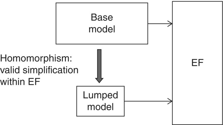
Figure 8.1 Validity of base and lumped models in Experimental Frame (EF).
Abstracting from base to lumped model presents a challenge in cyber system description due to the necessary context (e.g. representative Course of Action) that the cyber system portrays. In addition, the moving parts represented by the attack cycle, or representative taxonomy (e.g. ATT&CK, MACE, etc.) might be considered at this stage, concerning the role that vulnerability evaluation will play in what the overall model describes. Subsequent metrics might also be considered during the lumping to ensure that the final representation provides the analytical insight that the user is focused on.
While keeping the systems’ considerations in mind in abstracting the model, a key enabler for developing more capable simulators that build on Figure 8.1’s morphism example is the ability to construct lumped models, from individual base models, that represent more abstract system of systems (SoS) (Figure 8.2) (Zeigler and Nutaro 2016).
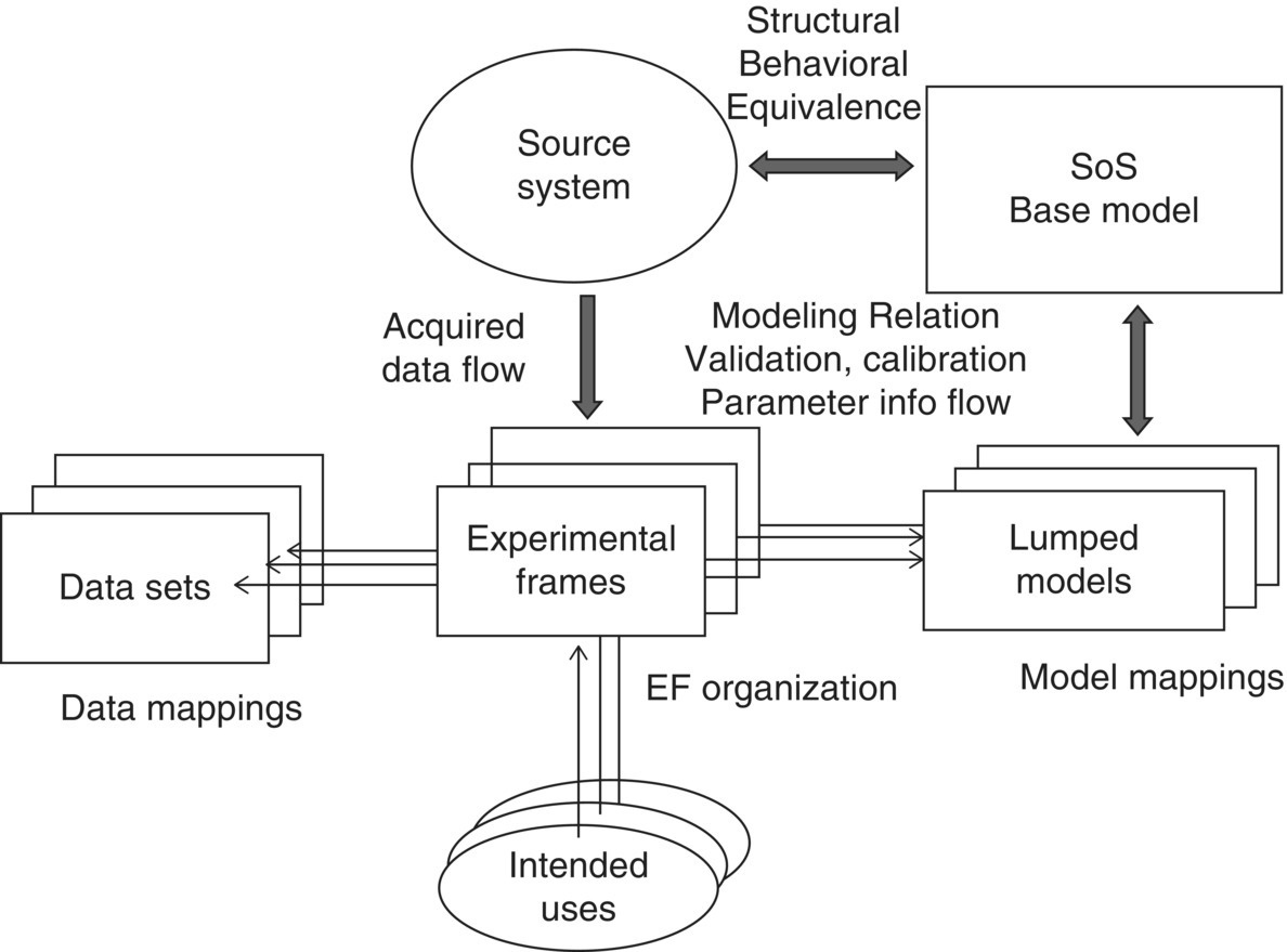
Figure 8.2 Architecture for System of Systems (SoS) Verification and Validation (V&V) based on M&S framework.
Figure 8.2 shows how the data sets, intended uses, and EFs roll up to provide both SoS base and lumped models; an aspirational approach for current cyber M&S. While Figure 8.2 provides an overview of all of the components for a constructive simulation system that incorporates mappings required for emulator incorporation into simulators, test beds are still the primary means for testing emulator/simulator combinations for cyber–physical systems. In addition, Kim et al. (2008) developed the DEVS/NS‐2 Environment for network‐based discrete event simulation within the DEVS framework for easy capture of EF and other DEVS‐based concepts presented here: NS‐2 sometimes viewed as a parallel to an emulation with its topology and node/link configuration requirements.
8.2.2 Cyber Emulators
Cyber ranges (CRs) often include elements of both emulation and simulation of networks. For example, exercises usually include simulation of an attack on the network and its progress, and countermeasures by human defenders. In addition, CRs leverage this paradigm, which is often used to evaluate a system or technology concept.
Several CRs are provided by Davis and Magrath (2013). Cyber VAN (Chadha et al. 2016) provides an example of a portable range for standard computing equipment, while mobile devices are profiled in (Serban et al. 2015). Each of the authors explored approaches used to build CRS, including the merits of each approach and their functionality. The review (Davis and Magrath 2013) first categorizes CRs by their type and second by their supporting sector: academic, military, or commercial, with their types described in Table 8.3.
Table 8.3 Cyber range types.
| Cyber range types | Description |
| Simulation | Uses software models of real‐world objects to explore behavior |
| Overlay | Operates on live production hardware with experiments sharing their production resources rather than using a dedicated CR laboratory |
| Emulation | Runs real software applications on dedicated hardware. Emulation refers to the software layer that allows fixed CR hardware to be reconfigured to different topologies for each experiment. |
CRs are usually used in conjunction with emulator/simulator combinations for evaluating overall systems.
8.2.3 Emulator/Simulator Combinations for Cyber Systems
While the theory is in place for providing valid cyber M&S, in practice, cyberphysical systems are still evaluated as independent functional manifestations on CRs composed of virtual machines. Modeling provides for the evaluation of system states, in the abstract, apart from the strict function calls found in software system regression testing. Leveraging both system state understanding and attack graphs (Jajodia et al. 2015), modeling provides the opportunity to clearly identify the system states that lead to the vulnerabilities enumerated by Cam (2015), and discussed more clearly in the MITRE ATT&CK framework. In addition, mapping a system’s state space also provides for the application of quality control approaches (e.g. factorial design, etc.) to better enumerate a system’s state combinations and potential vulnerabilities.
Attacks against cyber (IT) and physical (e.g. industrial control system, actuators, etc.) systems are usually evaluated independently, at present, emulating the individual systems of interest and their respective logical anomalies. The SoS that makes up a Cyber–Physical System (CPS) is therefore only evaluated component by component, intended uses of which may not account for system states found in combination.
Thus, there is a pressing need to evaluate both cyber and physical systems together for a rapidly growing number of applications using simulation and emulation in a realistic environment, which brings realistic attacks against the defensive capabilities of CPS. Without support from appropriate tools and run‐time environments, this assessment process can be extremely time‐consuming and error‐prone, if possible at all. Integrating simulation and emulation together, in a single platform for security experimentation, exists at the concept stage,1,2 further proving out the need for such an environment and bringing out some of the considerations required for a full‐scale application. Major components for a mixed simulation/emulation environment include (Yan et al. 2012):
- Modeling environment for system specification and experiment configuration.
- Run‐time environment that supports experiment execution.
At run time, the cyber simulator/emulator provides time synchronization and data communication, coordinating the execution of the security experiment across simulation and emulation platforms (Figure 8.3). As previously discussed (Chapter 7), COATS provides this hybrid simulation/emulation combination via communicating cyber effects from an emulation test bed to a more traditional command‐level training simulation environment.
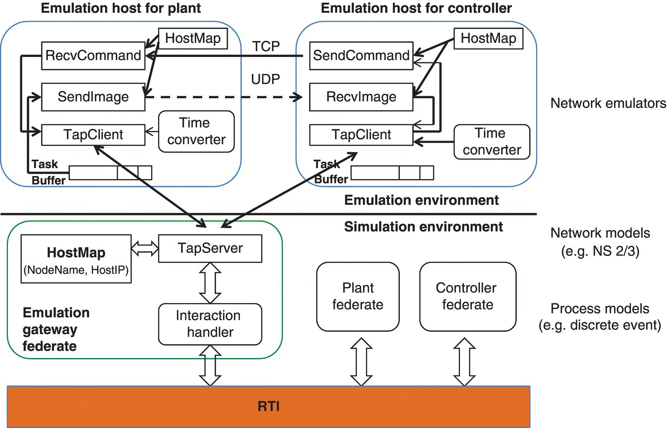
Figure 8.3 Emulator–simulator combination for Cyber–Physical System.
An extension of individual system testing, similar to the COATS (Morse et al. 2014a, b) example for incorporating cyber effects into training, requiring a combination of CRs (i.e. emulated environments) and trainees, there is also interest (often for engineering purposes) to combine range emulators with constructive simulations. Simulations have the potential to provide “cheap” scalability not available in other “real” applications.
A key addition in Figure 8.3’s combined emulation and simulation environment is the synchronization of temporal and data communications. As shown in Figure 8.4, this was a gap in DETERLAB and is handled in iSEE (Yan et al. 2012) setup (Figure 8.4).
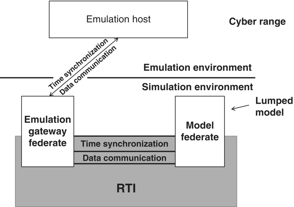
Figure 8.4 Time/data synchronization for combined emulation–simulation environment.
While Figure 8.4 provides a method for combining emulation and simulation environments for generalized cyber–physical testing, a cost and portability target for this work is to increasingly leverage structured modeling of both individual and SoS’, for valid evaluation of associated cyber systems.
8.2.4 Verification, Validation, and Accreditation (VV&A)
Leveraging simulations, and using EFs in particular, shows that the user has a clear picture of acceptance criteria for the final M&S system (Roza et al. 2010). The acceptance goal is to convincingly show that an M&S system will satisfy its purpose in use. This abstract acceptance goal is translated into a set of necessary and sufficient concrete acceptability criteria; criteria for which convincing evidence is obtained. General Methodology for Verification and Validation (GM‐VV) defines three classes of acceptability criteria for M&S artifacts, called VV&A properties (Figure 8.7) that each address and provide a set of assessment metrics for a specific part of an M&S artifact (Roza et al. 2013) (Table 8.4).
Table 8.4 Verification, Validation and Accreditation (VV&A) properties.
| Acceptability criteria for M&S artifacts | Verification, Validation, and Accreditation (VV&A) properties |
| Utility | Properties used to assess the effectiveness, efficiency, suitability, and availability of an M&S artifact in solving a problem statement in the problem world. Utility properties address aspects such as value, risk, and cost. |
| Validity | Properties that are used to assess the level of agreement of the M&S system replication of the real‐world systems it tries to represent, e.g. fidelity. Validity properties are also used to assess the consequences of fidelity discrepancies on the M&S system utility. |
| Correctness | Properties that assess whether the M&S system implementation that conform to the imposed requirements, and is free of error and of sufficient precision. Correctness metrics are also used to assess the consequences of implementation discrepancies on both validity and utility. |
While the GM‐VV (Roza et al. 2013) provides an overall process for system evaluation, each of the respective steps requires a tool to clarify whether the tool is verified (meets the specifications/requirements you have written – “Did I build what I said I would?”) and valid (addressed the business needs that caused you to write those requirements – “Did I build what I need?”). One way of representing system development incorporating these considerations is shown in Figure 8.5.
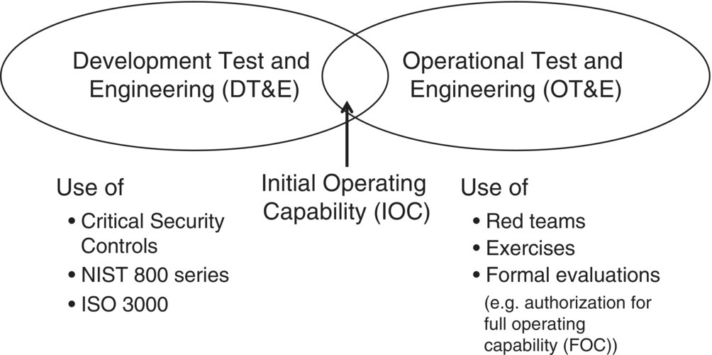
Figure 8.5 Development vs. operational testing – verification and validation.
One of GM‐VV’s tools to accomplish V&V is the goal claim network (Figure 8.6).
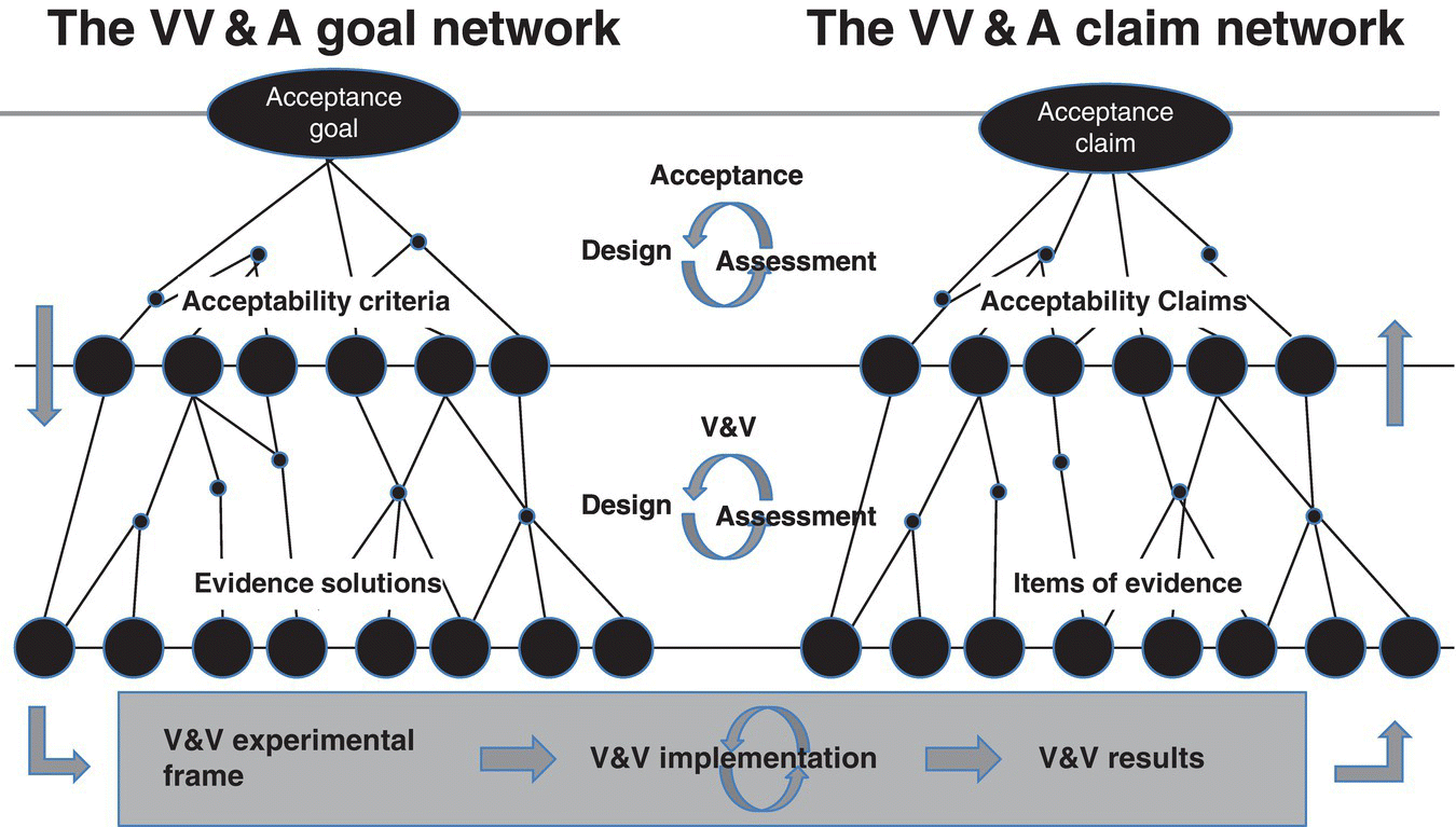
Figure 8.6 VV&A goal–claim network structure.
The VV&A goal–claim network is an information and argumentation structure rooted in both goal‐oriented requirements engineering and claim–argument–evidence safety engineering principles. The left part of the goal–claim network is used to derive the acceptability criteria from the acceptance goal; and design solutions for collecting evidence to demonstrate that the M&S system, intermediate product, or result satisfies these criteria. The acceptance goal reflects the VV&A needs and scope (e.g. system of interest, intended use). Evidence solutions include the specification of tests/experiments, referent for the simuland (e.g. expected results, observed real data), methods for comparing and evaluating the test/experimental results against the referent. Collectively, they specify the design of the V&V EF used to assess the M&S system and its results. When implemented, the EF produces the actual V&V results. After a quality assessment (e.g. for errors, reliability, and strength), these results can be used as the items of evidence in the right part of the goal–claim network. These items of evidence support the arguments that underpin the acceptability claims. An acceptability claim states whether a related acceptability criterion has been met or not. Acceptability claims provide the arguments for assessing whether or to what extent the M&S system and its results are acceptable for the intended use. This assessment results in an acceptance claim inside the VV&A goal–claim network.
Ideally, the goal–network is built in a top‐down manner and the claim network in a bottom‐up manner, as indicated by the rectangular arrows in Figure 8.6. However, in practice, the total VV&A goal–claim network is built iteratively as indicated by the circular arrows. The VV&A goal–claim network as such encapsulates, manages, and consolidates all underlying evidence and argumentation necessary for developing an appropriate and defensible acceptance recommendation.
In addition to the goal–claim network in providing a V&V framework, the GM‐VV (Roza et al. 2013) can also be constructed to preserve the attributes, or meta‐properties, used for system evaluation. Meta‐properties are used to assess the level of confidence with which the utility, validity, and correctness have been assessed, i.e. the convincing force of the evidence for these three properties. Meta‐properties typically include aspects such as completeness, consistency, independence, uncertainty, and relevance (Figure 8.7).

Figure 8.7 Utility, validity, correctness, and meta‐properties relationship diagram.
Figure 8.7 expands on the type of analysis possible, once a standard, reusable foundation for simulation (e.g. DEVS formalism) is relied upon for developing the representative component and system models (Table 8.5).
Table 8.5 Conceptual definitions of objects and modeling and simulation framework (MSF) equivalents.
| Object definition (conceptual) | M&S formalization |
| Simuland – real‐world system of interest; it is the object, process, or phenomenon to be simulated | Real‐world system is a source of data and can be represented by a system specification at a behavioral level |
| Model – simuland representation, broadly grouped into conceptual and executable types | A model is a set of rules for generating behavior and can be represented by a system specification at a structural level. A modeling formalism enables conceptual specification and is mapped to a simulation language for simulator execution |
| Simulation – process of executing a model over time | A simulator is a system capable of generating the behavior of a model; simulators come in classes corresponding to formalisms |
| Results – of simulation are the model’s output produced during simulation | Behavior of a model generated by a simulation constitutes a specification at the behavior level |
Table 8.5 provides some basic M&S definitions extensible to describing cyber systems. Additional work on quantifying the uncertainty (Grange and Deiotte 2015) in representations holds promise for increasing developer understanding on “how good” a model‐based simulation platform is for a particular cyber evaluation task.
8.3 Conclusions
The body of M&S theory exists for developing
- EFs that represent COAs.
- Mapping real‐world, emulator‐like, descriptions to mathematical objects (e.g. lumped models).
- Verifying and Validating that a cyber simulation is correct within the context of a given EF.
Providing valid simulations of cyber systems is still a manual process, ensuring that the respective EF describes the COA of interest, and making the argument that intended use has been met for V&V purposes. Fortunately, the GM‐VV ties up the combination of EFs, component verification, and project management into an overall structure usable to construct any kind of simulation (including cyber). GM‐VV is a Simulation Interoperability Standard’s Organization (SISO) standard. Having gone through a multiyear vetting process, GM‐VV is a good resource to leverage for verifying and validating cyber models.
8.4 Questions
- 1 Where do requirements fit into the constructing of a cyber model?
- 2 How is abstraction, from real world to model, usually accomplished?
- 3 What is the difference between a base and lumped model?
- 4 When is a cyber model verified?
- 5 What are the main issues in validating a cyber model?
- 6 What does an Experimental Frame (EF) provide the cyber modeler to facilitate V&V efforts?
- 7 Why is a goal–claim network a good approach for documenting model validity?
