30.2. Architectural Pattern: Layers
The essential ideas of the Layers pattern [BMRSS96] are simple:
Organize the large-scale logical structure of a system into discrete layers of distinct, related responsibilities, with a clean, cohesive separation of concerns such that the “lower” layers are low-level and general services, and the higher layers are more application specific.
Collaboration and coupling is from higher to lower layers; lower-to-higher layer coupling is avoided.
Solution
A layer is a large-scale element, often composed of several packages or subsystems.
The Layers pattern relates to the logical architecture; that is, it describes the conceptual organization of the design elements into groups, independent of their physical packaging or deployment.
Layers defines a general N-tier model for the logical architecture; it produces a layered architecture. It has been applied and written about so often as a pattern that the Pattern Almanac 2000 [Rising00] lists over 100 patterns that are variants of or related to the Layers pattern.
Source code changes are rippling throughout the system—many parts of the systems are highly coupled.
Problems
Application logic is intertwined with the user interface, and so can not be reused with a different interface, nor distributed to another processing node.
Potentially general technical services or business logic is intertwined with more application-specific logic, and so can not be reused, distributed to another node, or easily replaced with a different implementation.
There is high coupling across different areas of concern. It is thus difficult to divide the work along clear boundaries for different developers.
Due to the high coupling and mixing of concerns, it is hard to evolve the functionality, scale up the system, or update it to use new technologies.
The purpose and number of layers varies across applications and application domains (information systems, operating systems, and so forth. Applied to information systems, typical layers are illustrated and explained in Figure 30.1.
Figure 30.1. Common layers in an information system logical architecture.[1]
[1] The width of the package is used to communicate range of applicability in this diagram, but this is not a general UML practice. AKA means also known as.
Example
Based on these archetypes, Figure 30.2 illustrates a partial logical layered architecture for the NextGen application.
Figure 30.2. Partial logical view of layers in the NextGen application.
UML notation— Package diagrams are used to illustrate the layers. In the UML, a layer is simply a package.
Note the absence of an Application layer for this iteration of the design; as discussed later, it is not always necessary.
Since this is iterative development, it is normal to create a design of layers that starts simple, and evolves over the iterations of the elaboration phase. One goal of this phase is to have the core architecture established (designed and implemented) by the end of the iterations in elaboration, but this does not mean doing a large up-front speculative architectural design before starting to program. Rather, a tentative logical architecture is designed in the early iterations, and it evolves incrementally through the elaboration phase.
Observe that just a few sample types are present in this package diagram; this is not only motivated by limited page space in formatting this book, but is a signature quality of an architectural view diagram—it only shows a few noteworthy elements in order to concisely convey the major ideas of the architecturally significant aspects. The idea in a UP architectural view document is to say to the reader, “I've chosen this small set of instructive elements to convey the big ideas.”
Diagram Comments:
There are other types in these packages; only a few are shown to indicate noteworthy aspects.
The Foundation layer was not shown in this view; the architect (me) decided it did not add interesting information, even though the development team will certainly be adding some Foundation classes, such as more advanced String manipulation utilities.
For now, a separate Application layer is not used. The responsibilities of control or session objects in the Application layer are handled by the Register object. The architect will add an Application layer in a later iteration as the behavior grows in complexity, and alternative client interfaces are introduced (such as a web browser and wireless networked handheld PDA).
Inter-Layer and Inter-Package Coupling
It is also informative to include a diagram in the logical view that illustrates noteworthy coupling between the layers and packages. A partial example is illustrated in Figure 30.3.
Figure 30.3. Partial coupling between packages.
UML notation:
Observe that dependency lines can be used to communicate coupling between packages or types in packages. Plain dependency lines are excellent when the communicator does not care to be more specific on the exact dependency (attribute visibility, subclassing, ...), but just wants to highlight general dependencies.
Note also the use of a dependency line emitting from a package rather than a particular type, such as from the Sales package to POSRuleEngineFacade class, and the Domain package to the Log4J package. This is useful when either the specific dependent type is not interesting, or the communicator wants to suggest that many elements of the package may share that dependency.
Another common use of a package diagram is to hide the specific types, and focus on illustrating the package-package coupling, as in the partial diagram of Figure 30.4.
Figure 30.4. Partial package coupling.
In fact, Figure 30.4 illustrates probably the most common style of logical architecture diagram in the UML—a package diagram that shows between perhaps 5 to 20 major packages, and their dependencies.
Inter-Layer and Inter-Package Interaction Scenarios
Package diagrams show static information. To understand the dynamics of how objects across the layers connect and communicate, an interaction diagram is informative. In the spirit of an “architectural view” which hides uninteresting details, and emphasizes what the architect wants to convey, an interaction diagram in the logical view of the architecture focuses on the collaborations as they cross layer and package boundaries. A set of interaction diagrams that illustrate architecturally significant scenarios (in the sense that they illustrate many aspects of the large-scale or big ideas in the design) is thus useful.
For example, Figure 30.5 illustrates part of a Process Sale scenario that emphasizes the connection points across the layers and packages.
Figure 30.5. An architecturally significant interaction diagram that emphasizes cross-boundary connections.
UML notation:
The package of a type can optionally be shown by qualifying the type with the UML path name expression <PackageName>::<TypeName>. For example, Domain::Sales::Register. This can be exploited to highlight to the reader the inter-package and inter-layer connections in the interaction diagram.
Note also the use of the «subsystem» stereotype. In the UML, a subsystem is a discrete entity that has behavior and interfaces. A subsystem can be modeled as a special kind of package, or—as shown here—as an object, which is useful when one wants to show inter-subsystem (or system) collaborations. In the UML, the entire system is also a “subsystem” (the root one), and thus can also be shown as an object in interaction diagrams (such as an SSD).
Observe that the diagram ignores showing some messages, such as certain Sale collaborations, in order to highlight architecturally significant interactions.
Two design decisions at an architectural level are:
What are the big parts?
How are they connected?
Collaborations
Whereas the architectural Layers pattern guides defining the big parts, micro-architectural design patterns such as Facade, Controller, and Observer are commonly used for the design of the connections between layers and packages. This section examines patterns in connection and communication between layers and packages.
Simple Packages vs. Subsystems
Some packages or layers are not just conceptual groups of things, but are true subsystems with behavior and interfaces. To contrast:
The Pricing package is not a subsystem; it simply groups the factory and strategies used in pricing. Likewise with Foundation packages such as java.util.
On the other hand, the Persistence, POSRuleEngine, and Jess packages are subsystems. They are discrete engines with cohesive responsibilities that do work.
In the UML, a subsystem can be identified with a stereotype, as in Figure 30.6.
Figure 30.6. Subsystem stereotypes.
Facade
For packages that represent subsystems, the most common pattern of access is Facade, a GoF design pattern. That is, a public facade object defines the services for the subsystem, and clients collaborate with the facade, not internal subsystem components. This is true of the POSRuleEngineFacade and the PersistenceFacade for access to the rules engine and persistence subsystem.
The facade should not normally expose many low-level operations. Rather, it is desirable for the facade to expose a small number of high-level operations—the coarse-grained services. When a facade does expose many low-level operations,it tends to become incohesive. Furthermore, if the facade will be, or might become, a distributed or remote object (such as an EJB session bean, or RMI server object), fine-grained services lead to remote communication performance problems—lots of little remote calls are a performance bottleneck in distributed systems.
Also, a facade does not normally do its own work. Rather, it is consolidator or mediator to the underlying subsystem objects, which do the work.
For example, the POSRuleEngineFacade is the wrapper and single point of access into the rules engine for the POS application. Other packages do not see the implementation of this subsystem, as it is hidden behind the facade. Suppose (this is just one of many implementations) that the POS rules engine subsystem is implemented by collaborating with the Jess rules engine. Jess is a subsystem which exposes many fine-grained operations (this is common for very general, third-party subsystems). But the POSRuleEngineFacade does not expose the low level Jess operations in its interface. Rather, it provides only a few high-level operation such as isInvalid(lineItem, sale).
If the application has only a “small” number of system operations, then it is common for the Application or Domain layer to expose only one object to an upper layer. On the other hand, the Technical Services layer, which contains several subsystems, exposes at least one facade (or several public objects, if facades aren't used) for each subsystem to upper layers. See Figure 30.7.
Figure 30.7. Number of interfaces exposed to upper layers.
Session Facades and the Application Layer
In contrast to Figure 30.7, when an application has many system operations and supports many use cases, it is common to have more than one object mediating between the Presentation and Domain layers.
In the current version of the NextGen system, there is a simple design of a single Register object acting as the facade onto the Domain layer (by virtue of the GRASP controller pattern).
However, as the system grows to handle many use cases and system operations, it is not uncommon to introduce an Application layer of objects that maintain session state for the operations of a use case, where each session instance represents a session with one client. These are called Session Facades, and their use is another recommendation of the GRASP Controller pattern, such as in the use-case session facade controller variant of the pattern. See Figure 30.8 for an example of how the NextGen architecture may evolve with an Application layer and session facades.
Figure 30.8. Session facades and an Application Layer.
Controller
The GRASP Controller pattern describes common choices in client-side handlers (or controllers, as they've been called) for system operation requests emitting from the Presentation layer. Figure 30.9 illustrates.
Figure 30.9. The Controller choices.

System Operations and Layers
The SSDs illustrate the system operations, hiding presentation objects from the diagram. The system operations being invoked on the system in Figure 30.10 are requests being generated by an actor via the Presentation layer, onto the Application or Domain layer.
Figure 30.10. System operations in the SSDs and in terms of layers.
Upward Collaboration with Observer
The Facade pattern is commonly used for “downward” collaboration from a higher to a lower layer, or for access to services in another subsystem of the same layer. When the lower Application or Domain layer needs to communicate upward with the Presentation layer, it is usually via the Observer pattern. That is, UI objects in the higher Presentation layer implement an interface such as PropertyListener or AlarmListener, and are subscribers or listeners to events (such as property or alarm events) coming from objects in the lower layers. The lower layer objects are directly sending messages to the upper layer UI objects, but the coupling is only to the objects viewed as things that implement an interface such as PropertyListener, not viewed as specific GUI windows.
This was examined when the Observer pattern was introduced. Figure 30.11 summarizes the idea in relation to layers.
Figure 30.11. Observer for “upward” communication to the Presentation layer.
Relaxed Layered Coupling
The layers in most layered architectures are not coupled in the same limited sense as a network protocol based on the OSI 7-Layer Model. In the protocol model, there is strict restriction that elements of layer N only access the services of the immediate lower layer N-1.
This is rarely followed in information system architectures. Rather, the standard is a “relaxed layered” or “transparent layered” architecture [BMRSS96], in which elements of a layer collaborate with or are coupled to several other layers.
Comments on typical coupling between layers:
All higher layers have dependencies on the Technical Services and Foundations layer.
For example, in Java all layers depend on java.util package elements.
It is primarily the Domain layer that has dependency on the Business Infrastructure layer.
The Presentation layer makes calls on the Application layer, which makes service calls on the Domain layer; the Presentation layer does not call on the Domain, unless there is no Application layer.
If it is a single-process “desktop” application, software objects in the Domain layer are directly visible to, or passed between, Presentation, Application, and to a lesser extent, Technical Services.
For example, assuming the NextGen POS system is of this type, a Sale and a Payment object could be directly visible to the GUI Presentation Layer, and also passed into the Persistence subsystem in the Technical Services layer.
On the other hand, if it is a distributed system, then serializable replicates (also known as data holder or value objects) of objects in the Domain layer are usually passed to a Presentation layer. In this case, the Domain layer is deployed on a server computer, and client nodes get copies of server data.
Isn't Coupling to Technical Service and Foundation Layers Dangerous?
As the GRASP Protected Variations and Low Coupling discussions explored, it is not coupling per se that is a problem, but unnecessary coupling to variation and evolution points that are unstable and expensive to fix. There is very little justification in spending time and money attempting to abstract or hide something that is unlikely to change, or if it did, the change impact cost would be negligible. For example, if building a Java technologies application, what value is there in hiding the application from access to the Java libraries? High coupling into many points of the libraries is an unlikely problem, as they are (relatively) stable and ubiquitous.
In addition to the structural and collaboration issues discussed above for this pattern, other issues include the following.
Discussion
External Resources or External Database Layer at the Bottom?
Most systems rely on external resources or services, such as an Oracle database and a Novell LDAP naming and directory service. These are physical implementation components, not a layer in the logical view of the architecture.
Showing external resources such as a particular database in a layer “below” the Foundation layer (for example) mixes up the logical view and the deployment or implementation views of the architecture.
Rather, in terms of the logical view of the architecture and its layers, access to a particular set of persistent data (such as inventory data) can be viewed as a subdomain of the Domain Layer—the Inventory subdomain. And the general services that provide access to databases may be viewed as a Technical Service partition—the Persistence service. See Figure 30.12.
Figure 30.12. Mixing views of the architecture.
Logical vs. Process and Deployment Views of the Architecture
The architectural layers are a logical view of the architecture, not a deployment view of elements to processes and processing nodes. Depending on the platform, all layers could be deployed within the same process on the same node, such as an application within a handheld PDA, or spread across many computers and processes for a large-scale web application.
The UP Deployment Model that maps this logical architecture to processes and nodes is strongly influenced by the choice of software and hardware platform and associated application frameworks. For example, J2EE versus .NET influence the deployment architecture.
There are many ways to slice and dice these logical layers for deployment, and in general the subject of deployment architecture will only be lightly introduced, as it is non-trivial, largely outside the scope of the book, and dependent on detailed discussion of the chosen software platform, such as J2EE.
Optional Application Layer?
If present, the Application layer contains objects responsible for knowing the session state of clients, mediating between the Presentation and Domain layers, and controlling the flow of work.
The flow may be organized by controlling the order of windows or web pages, for example.
In terms of the GRASP patterns, GRASP Controller objects such as a use case facade controller are part of this layer. In distributed systems, components such as EJB session beans (and stateful session objects in general) are part of this layer.
In some applications, this layer is not required. It is useful (this is not an exhaustive list) when one or more of the following is true:
Multiple user interfaces (for example, web pages and a Swing GUI) will be used for the system. The Application layer objects can act as Adapters that collect and consolidate the data as needed for different UIs, and as Facades that wrap and hide access to the Domain layer.
It is a distributed system and the Domain layer is on a different node than the Presentation layer, and shared by multiple clients. It is usually necessary to keep track of session state, and Application layer objects are a useful choice for this responsibility.
The Domain Layer can not or should not maintain session state.
There is a defined workflow in terms of the controlled order of windows or web pages that must be presented.
Fuzzy Set Membership in Different Layers
Some elements are strongly a member of one layer; a Math class is part of the Foundation layer. However, especially between the Technical Services and Foundation layers, and Domain and Business Infrastructure, some elements are harder to classify, because the differentiation between these layers is, roughly, “high” versus “low,” or “specific” versus “general.” which are fuzzy set terms. This is normal, and it is seldom necessary to decide upon a definitive categorization—the development team may consider an element roughly part of the Technical Services and/or Foundations layer considered as a group, broadly called the Infrastructure layer.[2]
[2] Note that there are not well-established naming conventions for layers, and name overloading and contradiction in the architecture literature is common.
For example:
Suppose this is a Java technologies project, and the open source logging framework Log4J (part of the Jakarta project) has been chosen. Is logging part of the Technical Service or Foundation layer? Log4J is a low-level, small, general framework. It is moderately a member of both the Technical Services and the Foundations fuzzy sets.
Suppose this is a web application, and the Jakarta Struts framework for web applications has been chosen. Struts is a relatively high-level, large, specific technical framework. It is arguably strongly a member of the Technical Services set, and weakly a member of the Foundation set.
But, one person's High-level Technical Service is another's Foundation...
Finally, it is not the case that the libraries provided by a software platform only represent low-level Foundation services. For example, in both .NET and J2SE+J2EE, services include relatively high-level functions such as naming and directory services.
Terminology: Tiers, Layers, and Partitions
The original notion of a tier in architecture was a logical layer, not a physical node, but the word has become widely used to mean a physical processing node (or cluster of nodes), such as the “client tier” (the client computer). This presentation will avoid the term for clarity, but bear this in mind when reading architecture literature.
The layers of an architecture are said to represent the vertical slices, while partitions represent a horizontal division of relatively parallel subsystems of a layer. For example, the Services layer may be divided into partitions such as Security and Reporting (Figure 30.13).
In some contexts, adding layers introduces performance problems. For example, in a high-performance graphics-intensive game adding layers of abstraction and indirection on top of direct access to graphics card components may introduce performance problems.
Contraindications and Liabilities
The Layers pattern is one of several core architectural patterns; it is not applicable to every problem. For example, an alternate is Pipes and Filters [BMRSS96]. This is useful when the main theme of the application involves processing something through a series transformations, such as image transformations, and the ordering of the transformations is changeable. Yet even in the case when the highest level architectural pattern is Pipes and Filters, individual pipes or filters can be design with Layers.
In general, there is a separation of concerns, a separation of high from low-level services, and of application-specific from general services. This reduces coupling and dependencies, improves cohesion, increases reuse potential, and increases clarity.
Benefits
Related complexity is encapsulated and decomposable.
Some layers can be replaced with new implementations. This is generally not possible for lower-level Technical Service or Foundation layers (e.g., java.util), but may be possible for Presentation, Application, and Domain layers.
Lower layers contain reusable functions.
Some layers (primarily the Domain and Technical Services) can be distributed.
Development by teams is aided because of the logical segmentation.
Figure 30.13. Layers and partitions.
Implementing the Layers: People and Process
Implementation
It is common and recommended, within an iteration, to have a developer specialize within one layer or one service.
Yet, it is not the case that the entire project team focuses on one layer or service in an iteration. Rather, it is more common to implement vertical slices across the layers. This is the UP approach in the elaboration phase: Choose scenarios and requirements that force, in each iteration, a broad coverage across many architecturally significant packages/layers/subsystems, in order to reveal and stabilize the major architectural elements in the early iterations.
However, in this book, this approach was not illustrated in the NextGen case study, because to do so would require early discussion across many and vast topics—from GUI programming to object-relational mapping and optimizing SQL statements. The book case study has focused on the design of Domain layer objects, while recognizing that in reality there would be parallel work going on to develop other layers and subsystems.
The design principles illustrated for the case study are applicable in virtually all layers of the design.
Implementation View: Mapping Source Code Organization to Layers and Packages
Part of the UP Implementation Model is the organization of the source code. For languages such as Java or C#, which provide easy package (namespace) support, the mapping from the logical packaging to the implementation packaging is similar, with notable exceptions when third-party libraries are used.[3] In fact, it is only in the early stages of development, when packages have been speculatively drawn, but not implemented, that there are meaningful differences.
[3] C++ also supports namespaces, but it is awkward to use the language with dozens or hundreds of fine-grained namespaces; not so for Java or C#.
Over time, as the code base grows, it is common to abandon the early speculative drawings (such as the ones we have just seen), and instead use a reverse-engineering UML CASE tool that reads the source code and generates a package diagram. Then, these automatically generated package diagrams, which accurately reflect the code (the real design) become the basis for the logical view of the architecture.
To use Java as an example for mapping to implementation packages, the layers and packages illustrated in Figure 30.4 might map to Java package names as follows:
							// --- PRESENTATION
							com.foo.nextgen.ui.swing
							com.foo.nextgen.ui.text
							// --- DOMAIN
							// packages relatively specific to the NextGen project
							com.foo.nextgen.domain.sales
							com.foo.nextgen.domain.pricing
							com.foo.nextgen.domain.serviceaccess
							com.foo.nextgen.domain.posruleengine
							// packages that can easily be designed as
							// multi-application common business services
							com.foo.domain.inventory
							com.foo.domain.creditpayment
							// --- TECHNICAL SERVICES
							// our team creates
							com.foo.service.persistencelite
							// third party
							org.apache.log4j
							org.apache.soap.rpc
							jess
							// --- FOUNDATION
							// our team creates
							com.foo.util
							com.foo.stringutil
Notice that an effort has been made to avoid using a specific application qualifier (“nextgen”) in the package names unless necessary. For example, the UI packages are related to the NextGen application, and so are qualified with the application name com.foo.nextgen.ui.*.
To support reuse, one practice is to name elements in an application-independent manner, when appropriate. As a straightforward example, general purpose String utilities created by the NextGen team, are placed in com.foo.stringutils, not com.foo.nextgen.stringutils. Furthermore, com.foo.stringutils should be placed in the company's source code repository at a company level, rather than buried within the NextGen project's source code folders. You can't reuse it if you can't see it.
As another example, consider the services to access external third-party inventory and credit payment authorization systems. Although they were created by the NextGen team in the service of the NextGen POS project, they are general business services—one could imagine accessing inventory systems from within other applications; so too for credit payment authorization. Hence, com.foo.domain.inventory rather than com.foo.nextgen.domain.inventory.
On the other hand, the POSRuleEngine package is completely related to the NextGen POS project. Thus, com.foo.nextgen.domain.posruleengine.
If in doubt, qualify the package with the project name. It can always be refactored at a later date.
A vast number of modern object-oriented systems (from desktop applications to distributed J2EE web systems) are developed with Layers; it might be harder to find one that is not, than is. Going farther back in history:
Known Uses
Virtual Machines and Operating Systems
Starting in the 1960s, operating system architects advocated the design of operating systems in terms of clearly defined layers, where the “lower” layers encapsulated access to the physical resources and provided process and I/O services, and higher layers called on these services. These included Multics [CV65] and the THE system [Dijkstra68].
Earlier still—in the 1950s—researchers suggested the idea of a virtual machine (VM) with a bytecode universal machine language (for example, UNCOL [Conway1958]), so that applications could be written at higher layers in the architecture (and executed without recompilation across different platforms), on top of the virtual machine layer, which in turn would sit on top of the operating system and machine resources. A VM layered architecture was applied by Alan Kay in his landmark Flex object-oriented based personal computer system [Kay68] and later (1972) by Kay and Dan Ingalls in the influential Smalltalk virtual machine [GK76]—the progenitor of more recent VMs such as the Java Virtual Machine.
Information Systems: The Classic Three-Tier Architecture
An early influential description of a layered architecture for information systems that included a user interface and persistent storage of data was known as a three-tier architecture (Figure 30.14), described in the 1970s in [TK78]. The phrase did not achieve popularity until the mid 1990s, in part due to its promotion in [Gartner95] as a solution to problems associated with the widespread use of two-tier architectures.
Figure 30.14. Classic view of a three-tier architecture.
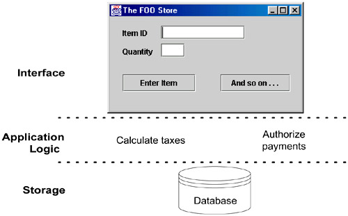
The original term is now less common, but its motivation is still relevant.
A classic description of the vertical tiers in a three-tier architecture is:
The singular quality of a three-tier architecture is the separation of the application logic into a distinct logical middle tier of software. The interface tier is relatively free of application processing; windows or web pages forward task requests to the middle tier. The middle tier communicates with the back-end storage layer.
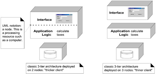
There was some misunderstanding that the original description implied or required a physical deployment on three computers, but the intended description was purely logical; the allocation of the tiers to compute nodes could vary from one to three. See Figure 30.15.
Figure 30.15. A three-tier logical division deployed in two physical architectures.
The three-tier architecture was contrasted by the Gartner Group with a two-tier design, in which, for example, application logic is placed within window definitions, which read and write directly to a database; there is no middle tier that separates out the application logic. Two-tier client-server architectures became especially popular with the rise of tools such as Visual Basic and PowerBuilder.
Two-tier designs have (in some cases) the advantage of initial quick development, but can suffer the complaints covered in the Problems section. Nevertheless, there are applications that are primarily simple CRUD (create, retrieve, update, delete) data intensive systems, for which this is a suitable choice.
Indirection— layers can add a level indirection to lower-level services.
Related Patterns
Protected Variation— layers can protect against the impact of varying implementations.
Low Coupling and High Cohesion— layers strongly support these goals.
Its application specifically to object-oriented information systems is described in [Fowler96].
Layered Architecture [Shaw96, Gemstone00]
Also Known As