4
Building Blocks
In this chapter you will
- Learn how to read schematic diagrams, the language of electronic circuits
- Be introduced to the capacitor
- Work with input pins
- Use arithmetic and test values
- Make decisions with
ifstatements - Learn the difference between analog and digital
- Measure analog voltage sources at different levels of precision
- Be introduced to variable resistors, piezoelectric buzzers, and temperature sensors
- Consolidate your knowledge by creating traffic lights, a battery tester, and a thermometer
The information in this chapter will help you understand an Arduino’s potential. We’ll continue to learn about electronics, including how to read schematic diagrams (the “road maps” of electronic circuits). We’ll also explore some new components and the types of signals that we can measure. Then we’ll discuss additional Arduino functions, such as storing values, performing mathematical operations, and making decisions. Finally, we’ll examine a few more components and put them to use in some useful projects.
Using Schematic Diagrams
Chapter 3 described how to build a circuit using physical layout diagrams to represent the breadboard and components mounted on it. Although such physical layout diagrams may seem like the easiest way to diagram a circuit, you’ll find that as more components are added, diagrams that are direct representations can become a real mess. Because our circuits are about to get more complicated, we’ll start using schematic diagrams (also known as circuit diagrams) to illustrate them, such as the one shown in Figure 4-1.
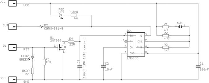
Figure 4-1: Example of a schematic diagram
Schematics are simply circuit road maps that show the path of the electrical current flowing through various components. Instead of showing components and wires, a schematic uses symbols and lines.
Identifying Components
Once you know what the symbols mean, reading a schematic is easy. To begin, let’s examine the symbols for the components we’ve already used.
The Arduino
Figure 4-2 shows a symbol for the Arduino itself. As you can see, all of the Arduino’s connections are displayed and neatly labeled.
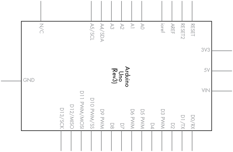
Figure 4-2: Arduino Uno symbol
The Resistor
The resistor symbol is shown in Figure 4-3.
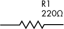
Figure 4-3: Resistor symbol
It’s good practice to display the resistor value and part designator along with the resistor symbol (220 Ω and R1 in this case). This makes life a lot easier for everyone trying to make sense of the schematic (including you). Often you may see ohms written as R instead—for example, 220 R.
The Rectifier Diode
The rectifier diode symbol is shown in Figure 4-4.

Figure 4-4: Rectifier diode symbol
Recall from Chapter 3 that rectifier diodes are polarized and current flows from the anode to the cathode. In the symbol shown in Figure 4-4, the anode is on the left and the cathode is on the right. An easy way to remember this is to think of current flowing toward the point of the triangle only. Current cannot flow the other way because the vertical bar “stops” it.
The LED
The LED symbol is shown in Figure 4-5.

Figure 4-5: LED symbol
All members of the diode family share a common symbol: the triangle and vertical line. However, LED symbols show two parallel arrows pointing away from the triangle to indicate that light is being emitted.
The Transistor
The transistor symbol is shown in Figure 4-6. We’ll use this to represent our BC548.
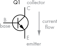
Figure 4-6: Transistor symbol
The vertical line at the top of the symbol (labeled C) represents the collector, the horizontal line at the left represents the base (labeled B), and the bottom line represents the emitter (labeled E). The arrow inside the symbol, pointing down and to the right, tells us that this is an NPN-type transistor, because NPN transistors allow current to flow from the collector to the emitter. (PNP-type transistors allow current to flow from the emitter to the collector.)
When numbering transistors we use the letter Q, just as we use R to number resistors.
The Relay
The relay symbol is shown in Figure 4-7.

Figure 4-7: Relay symbol
Relay symbols can vary in many ways and may have more than one set of contacts, but all relay symbols share certain elements in common. The first is the coil, which is the curvy vertical line at the left. The second element is the relay contacts. The COM (for common) contact is often used as an input, and the contacts marked NO (normally open) and NC (normally closed) are often used as outputs.
The relay symbol is always shown with the relay in the off state and the coil not energized—that is, with the COM and NC pins connected. When the relay coil is energized, the COM and NO pins will be connected in the symbol.
Wires in Schematics
When wires cross or connect in schematics, they are drawn in particular ways, as shown in the following examples.
Crossing but Not Connected Wires
When two wires cross but are not connected, the crossing can be represented in one of two ways, as shown in Figure 4-8. There is no one right way; it’s a matter of preference.
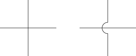
Figure 4-8: Non-connecting crossed wires
Connected Wires
When wires are meant to be physically connected, a junction dot is drawn at the point of connection, as shown in Figure 4-9.

Figure 4-9: Two wires that are connected
Wire Connected to Ground
When a wire is connected back to ground (GND), the standard method is to use the symbol shown in Figure 4-10.

Figure 4-10: The GND symbol
The GND symbol at the end of a line in a schematic in this book tells you that the wire is physically connected to the Arduino GND pin.
Dissecting a Schematic
Now that you know the symbols for various components and their connections, let’s dissect the schematic we would draw for Project 1, on page 33 in Chapter 3. Recall that you made five LEDs blink backward and forward.
Compare the schematic shown in Figure 4-11 with Figure 3-13 on page 34, and you’ll see that using a schematic is a much easier way to describe a circuit.
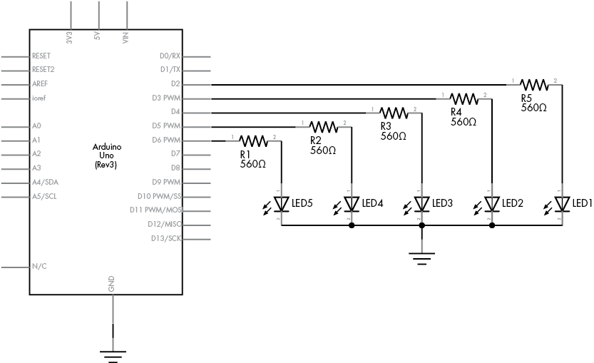
Figure 4-11: Schematic for Project 1
From now on, we’ll use schematics to describe circuits, and I’ll show you the symbols for new components as they’re introduced.
The Capacitor
A capacitor is a device that holds an electric charge. It consists of two conductive plates sandwiching an insulating layer that allows an electric charge to build up between the plates. When the current is stopped, the charge remains and can flow out of the capacitor (called discharging the capacitor) as soon as the charge voltage stored in the capacitor is presented with a new path for the current to take.
Measuring the Capacity of a Capacitor
The amount of charge that a capacitor can store is measured in farads, and one farad is actually a very large amount. Therefore, you will generally find capacitors with values measured in picofarads or microfarads. One picofarad (pF) is 0.000000000001 of a farad, and one microfarad (μF) is 0.000001 of a farad. Capacitors are also manufactured to accept certain voltage maximums. In this book we’ll be working with low voltages only, so we won’t be using capacitors rated at greater than 10 V or so; it’s generally fine, however, to use higher-voltage capacitors in lower-voltage circuits. Common voltage ratings are 10, 16, 25, and 50 V.
Reading Capacitor Values
Reading the value of a ceramic capacitor takes some practice, because the value is printed in a sort of code. The first two digits represent the value in picofarads, and the third digit is the multiplier in tens. For example, the capacitor shown in Figure 4-12 is labeled 104. This equates to 10 followed by four zeros, or 100,000 pF (which is 100 nanofarads [nF] or 0.1 μF).
Types of Capacitors
Our projects will use two types of capacitors: ceramic and electrolytic.
Ceramic Capacitors
Ceramic capacitors, such as the one shown in Figure 4-12, are very small and therefore hold a small amount of charge. They are not polarized and can be used for current flowing in either direction. The schematic symbol for a non-polarized capacitor is shown in Figure 4-13.

Figure 4-12: A 0.1 µF ceramic capacitor

Figure 4-13: Non-polarized capacitor schematic symbol, with the capacitor’s value shown at the upper right
Ceramic capacitors work beautifully in high-frequency circuits because they can charge and discharge very quickly due to their small capacitance.
Electrolytic Capacitors
Electrolytic capacitors, like the one shown in Figure 4-14, are physically larger than ceramic types, offer increased capacitance, and are polarized. A marking on the cover shows either the positive (+) side or the negative (–) side. In Figure 4-14, you can see the stripe and the small negative (–) symbol that identifies the negative side. Like resistors, capacitors also have a level of tolerance with their values. The capacitor in Figure 4-14 has a tolerance of 20 percent and a capacitance of 100 μF.

Figure 4-14: An electrolytic capacitor
The schematic symbol for electrolytic capacitors, shown in Figure 4-15, includes the + symbol to indicate the capacitor’s polarity.

Figure 4-15: Polarized capacitor schematic symbol
Electrolytic capacitors are often used to store larger electric charges and to smooth power supply voltages. Like a small temporary battery, they can smooth out the power supply and provide stability near circuits or parts that draw high currents quickly from the supply. This prevents unwanted dropouts and noise in your circuits. Luckily, the values of the electrolytic capacitor are printed clearly on the outside and don’t require decoding or interpretation.
You already have some experience generating basic forms of output using LEDs with your Arduino. Now it’s time to learn how to send input from the outside world into your Arduino using digital inputs, and to make decisions based on that input.
Digital Inputs
In Chapter 3, we used digital I/O pins as outputs to turn LEDs on and off. We can use these same pins to accept input from users—as long as we limit our information to two states, high and low.
The simplest form of digital input is a push button; several push buttons are shown in Figure 4-16. You can insert one of these directly into your solderless breadboard and wire it to an Arduino pin. When the button is pressed, current flows through the switch and into the digital input pin, which detects the presence of the voltage.
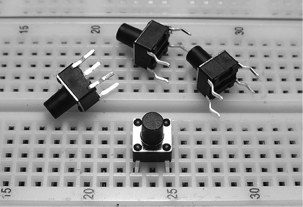
Figure 4-16: Basic push buttons on a breadboard
Notice that the button at the bottom of the figure is inserted into the breadboard, bridging rows 23 and 25. When the button is pressed, it connects the two rows. The schematic symbol for this push button is shown in Figure 4-17. The symbol represents the two sides of the button, which are numbered with the prefix S. When the button is pressed, the line bridges the two halves and allows voltage or current through.
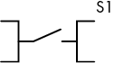
Figure 4-17: Push button schematic symbol
Project #4: Demonstrating a Digital Input
Our goal in this project is to create a button that turns on an LED for half a second when pressed.
The Algorithm
Here is our algorithm:
- Test whether the button has been pressed.
- If the button has been pressed, turn on the LED for half a second and then turn it off.
- If the button has not been pressed, do nothing.
- Repeat indefinitely.
The Hardware
Here’s what you’ll need to create this project:
- One push button
- One LED
- One 560 Ω resistor
- One 10 kΩ resistor
- One 100 nF capacitor
- Various connecting wires
- One breadboard
- Arduino and USB cable
The Schematic
First, we create the circuit on the breadboard with the schematic shown in Figure 4-19. Notice that the 10 kΩ resistor is connected between GND and digital pin 7. We call this a pull-down resistor, because it pulls the voltage at the digital pin almost to zero. Furthermore, by adding a 100 nF capacitor across the 10 kΩ resistor, we create a simple debounce circuit to help filter out the switch bounce. When the button is pressed, the digital pin goes immediately to high. But when the button is released, digital pin 7 is pulled down to GND via the 10 kΩ resistor, and the 100 nF capacitor creates a small delay. This effectively covers up the bouncing pulses by slowing the drop of the voltage to GND, thereby eliminating most of the false readings due to floating voltage and erratic button behavior.
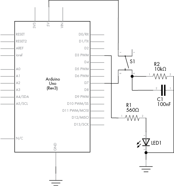
Figure 4-19: Schematic for Project 4
Because this is the first time you’re building a circuit with a schematic, follow these step-by-step instructions as you walk through the schematic; this should help you understand how the components connect:
- Insert the push button into the breadboard, as shown in Figure 4-20.

Figure 4-20: The push button inserted into the breadboard
- Now insert the 10 kΩ resistor, a short link wire, and the capacitor, as shown in Figure 4-21.

Figure 4-21: Adding the 10 kΩ resistor and the capacitor
- Connect one wire from the Arduino 5 V pin to the upper-right row for the button on the breadboard. Connect another wire from the Arduino GND pin to the same vertical row that connects to the left-hand sides of the wire link and the resistor. This is shown in Figure 4-22.
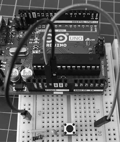
Figure 4-22: Connecting the 5 V (red) and GND (black) wires
- Run a wire from Arduino digital pin 7 to the lower-right row for the button on the breadboard, as shown in Figure 4-23.
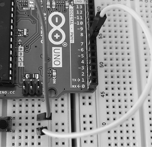
Figure 4-23: Connecting the button to the digital input
- Insert the LED into the breadboard with the short leg (the cathode) connected to the GND column and the long leg (the anode) in a row to the right. Next, connect the 560 Ω resistor to the right of the LED, as shown in Figure 4-24.

Figure 4-24: Inserting the LED and 560 Ω resistor
- Connect a wire from the right side of the 560 Ω resistor to Arduino digital pin 3, as shown in Figure 4-25.
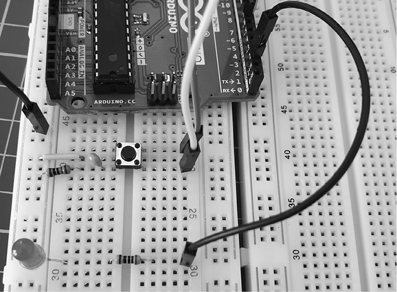
Figure 4-25: Connecting the LED branch to the Arduino
Before continuing, review the schematic for this circuit and check that your components are wired correctly. Compare the schematic against the actual wiring of the circuit.
The Sketch
For the sketch, enter and upload Listing 4-1.
// Listing 4-1, Project 4 - Demonstrating a Digital Input
1 #define LED 3
#define BUTTON 7

void setup()
{
2    pinMode(LED, OUTPUT);   // output for the LED
   pinMode(BUTTON, INPUT); // input for the button
}

void loop()
{
   if ( digitalRead(BUTTON) == HIGH )
   {
      digitalWrite(LED, HIGH); // turn on the LED
      delay(500);              // wait for 0.5 seconds
      digitalWrite(LED, LOW);  // turn off the LED
   }
}
Listing 4-1: Digital input
After you’ve uploaded your sketch, tap the push button briefly. Your LED should stay on for half a second.
Understanding the Sketch
Let’s examine the new items in the sketch for Project 4—specifically, #define, digital input pins, and the if statement.
Creating Constants with #define
Before void setup(), we use #define statements at 1 to create fixed values: when the sketch is compiled, the IDE replaces any instance of the defined word with the number that follows it. For example, when the IDE sees LED in the line at 2, it replaces it with the number 3. Notice that we do not use a semicolon after a #define value.
We’re basically using the #define statements to label the digital pins for the LED and button in the sketch. It’s a good idea to label pin numbers and other fixed values (such as a time delay) in this way, because if the value is used repeatedly in the sketch, then you won’t have to edit the same item more than once. In this example, LED is used three times in the sketch, but to change this value we’d have to edit its definition only once in its #define statement.
Reading Digital Input Pins
To read the status of a button, we first define a digital I/O pin as an input in void setup() using the following:
pinMode(BUTTON, INPUT); // input for buttonNext, to discover whether the button is connecting a voltage through to the digital input (that is, it’s being pressed), we use digitalRead(pin), where pin is the digital pin number to read. The function returns either HIGH (voltage is close to 5 V at the pin) or LOW (voltage is close to 0 V at the pin).
Making Decisions with if
Using if, we can make decisions in our sketch and tell the Arduino to run different code depending on the decision. For example, in the sketch for Project 4, we used Listing 4-2.
// Listing 4-2
if (digitalRead(BUTTON) == HIGH)
{
   digitalWrite(LED, HIGH); // turn on the LED
   delay(500);              // wait for 0.5 seconds
   digitalWrite(LED, LOW);  // turn off the LED
}
Listing 4-2: A simple if-then example
The first line in this code snippet begins with if because it tests for a condition. If the condition is true (that is, if the voltage is HIGH), then it means that the button is pressed. The Arduino will then run the code that is inside the curly brackets.
To determine whether the button is pressed (digitalRead(BUTTON) is set to HIGH), we use a comparison operator, a double equal sign (==). If we were to replace == with != (not equal to) in the sketch, then the LED would turn off when the button is pressed instead. Try it and see.
Once you’ve had some success, try changing the length of time that the light stays on, or go back to Project 3 on page 38 in Chapter 3 and add a push button control. (Don’t disassemble this circuit, though; we’ll use it again in the next example.)
Modifying Your Sketch: Making More Decisions with if-else
You can add another action to an if statement by using else. For example, if we rewrite Listing 4-1 by adding an else clause, as shown in Listing 4-3, then the LED will turn on if the button is pressed, or else it will be off. Using else forces the Arduino to run another section of code if the test in the if statement is not true.
// Listing 4-3
#define LED 3
#define BUTTON 7

void setup()
{
   pinMode(LED, OUTPUT);   // output for the LED
   pinMode(BUTTON, INPUT); // input for the button
}

void loop()
{
   if ( digitalRead(BUTTON) == HIGH )
   {
      digitalWrite(LED, HIGH);
   }
   else
   {
      digitalWrite(LED, LOW);
   }
}
Listing 4-3: Adding else
Boolean Variables
Sometimes you need to record whether something is in either of only two states, such as on or off, or hot or cold. A Boolean variable is the legendary computer “bit” whose value can be only a zero (0, false) or one (1, true). As with any other variable, we need to declare it in order to use it:
boolean raining = true; // create the variable "raining" and first make it trueWithin the sketch, you can change the state of a Boolean with a simple reassignment, such as this:
raining = false;Because Boolean variables can only take on the values of true or false, they are well suited to making decisions using if. True/false Boolean comparisons work well with the comparison operators != and ==. Here’s an example:
if ( raining == true )
{
   if ( summer != true )
   {
      // it is raining and not summer
   }
}
Comparison Operators
We can use various operators to make decisions about two or more Boolean variables or other states. These include the operators not (!), and (&&), and or (||).
The not Operator
The not operator is denoted by an exclamation mark (!). This operator is used as an abbreviation for checking whether something is not true. Here’s an example:
if ( !raining )
{
   // it is not raining (raining == false)
}
The and Operator
The logical and operator is denoted by &&. Using and helps reduce the number of separate if tests. Here’s an example:
if (( raining == true ) && ( !summer ))
{
   // it is raining and not summer (raining == true and summer == false)
}
The or Operator
The logical or operator is denoted by ||. Using or is pretty intuitive. Here’s an example:
if (( raining == true ) || ( summer == true ))
{
   // it is either raining or summer
}
Making Two or More Comparisons
You can also make two or more comparisons using the same if statement. Here’s an example:
if ( snow == true && rain == true && !hot )
{
   // it is snowing and raining and not hot
}
And you can use parentheses to set the order of operation. In the next example, the comparison in the parentheses is checked first and given a true or false state, and then that condition is subjected to the remaining test in the if statement:
if (( snow == true || rain == true ) && hot == false))
{
// it is either snowing or raining, and not hot
}
Lastly, just like the examples of the not (!) operator before a value, simple true/false tests can be performed without requiring == true or == false in each test. The following code has the same effect as the preceding example:
if (( snow || rain ) && !hot )
{
   // it is either snowing or raining, and not hot
   // ( snow is true OR rain is true ) AND it is not hot
}
As you can see, it’s possible to have the Arduino make a multitude of decisions using Boolean variables and comparison operators. Once you move on to more complex projects, this will become very useful.
Project #5: Controlling Traffic
Now let’s put our newfound knowledge to use by solving a hypothetical problem. As the town planners for a rural county, we have a problem with a single-lane bridge that crosses the river. Every week, one or two accidents occur at night, when tired drivers rush across the bridge without first stopping to see if the road is clear. We have suggested that traffic lights be installed, but the mayor wants to see them demonstrated before signing off on the purchase. We could rent temporary lights, but they’re expensive. Instead, we’ve decided to build a model of the bridge with working traffic lights using LEDs and an Arduino.
The Goal
Our goal is to install three-color traffic lights at each end of the single-lane bridge. The lights allow traffic to flow in only one direction at a time. When sensors located at either end of the bridge detect a car waiting at a red light, the lights will change and allow the traffic to flow in the opposite direction.
The Algorithm
We’ll use two buttons to simulate the vehicle sensors at each end of the bridge. Each set of lights will have red, yellow, and green LEDs. Initially, the system will allow traffic to flow from west to east, so the west-facing lights will be set to green and the east-facing lights will be set to red.
When a vehicle approaches the bridge (modeled by pressing the button) and the light is red, the system will turn the light on the opposite side from green to yellow to red, and then wait a set period of time to allow any vehicles already on the bridge to finish crossing. Next, the yellow light on the waiting vehicle’s side will blink as a “get ready” notice for the driver, and finally the light will change to green. The light will remain green until a vehicle approaches the other side, at which point the process repeats.
The Hardware
Here’s what you’ll need to create this project:
- Two red LEDs (LED1 and LED2)
- Two yellow LEDs (LED3 and LED4)
- Two green LEDs (LED5 and LED6)
- Six 560 Ω resistors (R1 to R6)
- Two 10 kΩ resistors (R7 and R8)
- Two 100 nF capacitors (C1 and C2)
- Two push buttons (S1 and S2)
- One medium-sized breadboard
- Arduino and USB cable
- Various connecting wires
The Schematic
Because we’re controlling only six LEDs and receiving input from two buttons, the design will not be too difficult. Figure 4-26 shows the schematic for our project.

Figure 4-26: Schematic for Project 5
This circuit is basically a more elaborate version of the button and LED circuit in Project 4, with resistors, more LEDs, and another button.
Be sure that the LEDs are inserted in the correct direction: the resistors connect to LED anodes, and the LED cathodes connect to the Arduino GND pin, as shown in Figure 4-27.
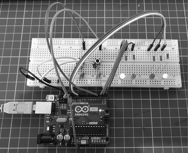
Figure 4-27: The completed circuit
The Sketch
And now for the sketch. Can you see how it matches our algorithm?
// Project 5 - Controlling Traffic

// define the pins that the buttons and lights are connected to:
1 #define westButton 3
#define eastButton 13
#define westRed 2
#define westYellow 1
#define westGreen 0
#define eastRed 12
#define eastYellow 11
#define eastGreen 10

#define yellowBlinkTime 500 // 0.5 seconds for yellow light blink

2 boolean trafficWest = true; // west = true, east = false
3 int flowTime = 10000;       // amount of time to let traffic flow
4 int changeDelay = 2000;     // amount of time between color changes

void setup()
{
   // set up the digital I/O pins
   pinMode(westButton, INPUT);
   pinMode(eastButton, INPUT);
   pinMode(westRed, OUTPUT);
   pinMode(westYellow, OUTPUT);
   pinMode(westGreen, OUTPUT);
   pinMode(eastRed, OUTPUT);
   pinMode(eastYellow, OUTPUT);
   pinMode(eastGreen, OUTPUT);
   // set initial state for lights - west side is green first
   digitalWrite(westRed, LOW);
   digitalWrite(westYellow, LOW);
   digitalWrite(westGreen, HIGH);
   digitalWrite(eastRed, HIGH);
   digitalWrite(eastYellow, LOW);
   digitalWrite(eastGreen, LOW);
}

void loop()
{
   if ( digitalRead(westButton) == HIGH ) // request west>east traffic flow
   {
      if ( trafficWest != true )
      // only continue if traffic flowing in the opposite (east) direction
      {
         trafficWest = true; // change traffic flow flag to west>east
         delay(flowTime);    // give time for traffic to flow
         digitalWrite(eastGreen, LOW); // change east-facing lights from green
                                       // to yellow to red
         digitalWrite(eastYellow, HIGH);
         delay(changeDelay);
         digitalWrite(eastYellow, LOW);
         digitalWrite(eastRed, HIGH);
         delay(changeDelay);
         for ( int a = 0; a < 5; a++ ) // blink yellow light
         {
             digitalWrite(westYellow, LOW);
             delay(yellowBlinkTime);
             digitalWrite(westYellow, HIGH);
             delay(yellowBlinkTime);
        }
       digitalWrite(westYellow, LOW);
       digitalWrite(westRed, LOW); // change west-facing lights from red
                                   // to green
       digitalWrite(westGreen, HIGH);
       }
   }
   if ( digitalRead(eastButton) == HIGH ) // request east>west traffic flow
   {
   if ( trafficWest == true )
   // only continue if traffic flow is in the opposite (west) direction
   {
      trafficWest = false; // change traffic flow flag to east>west
      delay(flowTime);     // give time for traffic to flow
      digitalWrite(westGreen, LOW);
      // change west-facing lights from green to yellow to red
      digitalWrite(westYellow, HIGH);
      delay(changeDelay);
      digitalWrite(westYellow, LOW);
      digitalWrite(westRed, HIGH);
      delay(changeDelay);
      for ( int a = 0 ; a < 5 ; a++ ) // blink yellow light
      {
         digitalWrite(eastYellow, LOW);
         delay(yellowBlinkTime);
         digitalWrite(eastYellow, HIGH);
         delay(yellowBlinkTime);
      }
      digitalWrite(eastYellow, LOW);
      digitalWrite(eastRed, LOW); // change east-facing lights from red
                                  // to green
      digitalWrite(eastGreen, HIGH);
      }
   }
}
Our sketch starts by using #define at 1 to associate digital pin numbers with labels for all the LEDs used, as well as the two buttons. We have red, yellow, and green LEDs and a button each for the west and east sides of the bridge. The Boolean variable trafficWest at 2 is used to keep track of which way the traffic is flowing—true is west to east, and false is east to west.
The integer variable flowTime at 3 is the minimum period of time that vehicles have to cross the bridge. When a vehicle pulls up at a red light, the system extends this period to give the opposing traffic time to cross the bridge. The integer variable changeDelay at 4 is the elapsed time between changes of color from green to yellow to red.
Before the sketch enters the void loop() section, it is set for traffic to flow from west to east in void setup().
Running the Sketch
Once it’s running, the sketch does nothing until one of the buttons is pressed. When the east button is pressed, the line:
if ( trafficWest == true )ensures that the lights change only if the traffic is heading in the opposite direction. The rest of the void loop() section is composed of a simple sequence of waiting and then of turning on and off various LEDs to simulate the traffic lights’ operation.
Analog vs. Digital Signals
In this section you’ll learn the difference between digital and analog signals, and you’ll learn how to measure analog signals with the analog input pins.
Until now, our sketches have been using digital electrical signals, with just two discrete levels. Specifically, we used digitalWrite(pin, HIGH) and digitalWrite(pin, LOW) to blink an LED and digitalRead() to measure whether a digital pin had a voltage applied to it (HIGH) or not (LOW). Figure 4-28 is a visual representation of a digital signal that alternates between high and low.

Figure 4-28: A digital signal, with highs appearing as horizontal lines at the top and lows appearing at the bottom
Unlike digital signals, analog signals can vary with an indefinite number of steps between high and low. For example, Figure 4-29 shows the analog signal of a sine wave. Notice that as time progresses, the voltage floats fluidly between high and low levels.

Figure 4-29: An analog signal of a sine wave
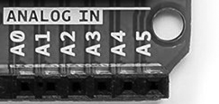
Figure 4-30: Analog inputs on the Arduino Uno
With our Arduino, high is closer to 5 V and low is closer to 0 V, or GND. We can measure the voltage values of an analog signal with our Arduino using the six analog inputs shown in Figure 4-30. These analog inputs can safely measure voltages from 0 (GND) to no more than 5 V.
If you use the function analogRead(), then the Arduino will return a number between 0 and 1,023 in proportion to the voltage applied to the analog pin. For example, you might use analogRead() to store the value of analog pin 0 in the integer variable a, as shown here:
a = analogRead(0); // read analog input pin 0 (A0)
// returns 0 to 1023, which is usually 0.000 to 4.995 volts
Project #6: Creating a Single-Cell Battery Tester
Although the popularity and use of cell batteries has declined, most people still have a few devices around the house, such as remote controls, clocks, or children’s toys, that use AA, AAA, C, or D cell batteries. These batteries carry much less than 5 V, so we can measure a cell’s voltage with our Arduino to determine the state of the cell. In this project, we’ll create a battery tester.
The Goal
Single-cell batteries such as AAs usually have a voltage of about 1.6 V when new, which decreases with use and age. We will measure the voltage and express the battery condition visually with LEDs. We’ll use the reading from analogRead(), which we will convert to volts. The maximum voltage that can be read is 5 V, so we divide 5 by 1,024 (the number of possible values), which equals 0.0048. We multiply the value returned by analogRead() by this number to get the reading in volts. For example, if analogRead() returns 512, then we multiply that reading by 0.0048, which equals 2.4576 V.
The Algorithm
Here’s the algorithm for our battery tester:
- Read from analog pin 0.
- Multiply the reading by 0.0048 to create a voltage value.
- If the voltage is greater than or equal to 1.6 V, briefly turn on a green LED.
- If the voltage is greater than 1.4 V and less than 1.6 V, briefly turn on a yellow LED.
- If the voltage is less than 1.4 V, briefly turn on a red LED.
- Repeat indefinitely.
The Hardware
Here’s what you’ll need to create this project:
- Three 560 Ω resistors (R1 to R3)
- One green LED (LED1)
- One yellow LED (LED2)
- One red LED (LED3)
- One breadboard
- Various connecting wires
- Arduino and USB cable
The Schematic
The schematic for the single-cell battery tester circuit is shown in Figure 4-31. On the left side, notice the two terminals, labeled + and –. Connect the matching sides of the single-cell battery to be tested at those points. Positive should connect to positive, and negative should connect to negative.
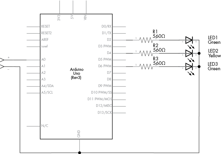
Figure 4-31: Schematic for Project 6
The Sketch
Now for the sketch. Since analog values can drift between integers, we’re going to use a new type of variable called a float, which can contain fractional or decimal values:
// Project 6 - Creating a Single-Cell Battery Tester
#define newLED 2 // green LED
#define okLED 4  // yellow LED
#define oldLED 6 // red LED

int analogValue = 0;
1 float voltage = 0;
int ledDelay = 2000;

void setup()
{
   pinMode(newLED, OUTPUT);
   pinMode(okLED, OUTPUT);
   pinMode(oldLED, OUTPUT);
}

void loop()
{
2    analogValue = analogRead(0);
3    voltage = 0.0048*analogValue;
4    if ( voltage >= 1.6 )
   {
      digitalWrite(newLED, HIGH);
      delay(ledDelay);
      digitalWrite(newLED, LOW);
   }
5    else if ( (voltage < 1.6) && (voltage) > 1.4 )
   {
      digitalWrite(okLED, HIGH);
      delay(ledDelay);
      digitalWrite(okLED, LOW);
    }
6     else if ( voltage <= 1.4 )
       {
         digitalWrite(oldLED, HIGH);
         delay(ledDelay);
         digitalWrite(oldLED, LOW);
      }
}
In this sketch, the Arduino takes the value measured by analog pin 0 at 2 and converts this to a voltage at 3. You’ll learn more about the new type of variable, the float at 1, in the next section, which discusses doing arithmetic with an Arduino and using comparison operators to compare numbers.
Doing Arithmetic with an Arduino
Like a pocket calculator, the Arduino can perform calculations such as multiplication, division, addition, and subtraction. Here are some examples:
a = 100;
b = a + 20;
c = b - 200;
d = c + 80; // d will equal 0
Float Variables
When you need to deal with numbers with a decimal point, you can use the variable type float. The values that can be stored in a float fall between 3.4028235 × 1038 and −3.4028235 × 1038 and are generally limited to six or seven decimal places of precision. You can mix integers and float numbers in your calculations. For example, you could add the float number f to the integer a and store the sum as the float variable g:
int a = 100;
float f;
float g;

f = a / 3; // f = 33.333333
g = a + f; // g = 133.333333
Comparison Operators for Calculations
We used comparison operators such as == and != with if statements and digital input signals in Project 5. In addition to these operators, we can use the following to compare numbers or numerical variables:
<Less than>Greater than<=Less than or equal to>=Greater than or equal to
We used these operators to compare numbers in lines 4, 5, and 6 in the sketch for Project 6.
Improving Analog Measurement Precision with a Reference Voltage
As demonstrated in Project 6, the analogRead() function returns a value proportional to a voltage between 0 and 5 V. The upper value (5 V) is the reference voltage, the maximum voltage that the Arduino analog inputs will accept and return the highest value for (1,023).
To increase precision while reading even lower voltages, we can use a lower reference voltage. For example, when the reference voltage is 5 V, analogRead() represents this with a value from 0 to 1,023. However, if we needed to measure only a voltage with a maximum of 2 V, then we could alter the Arduino output to represent 2 V using the 0 to 1,023 range to allow for more precise measurement. You can do this with either an external or internal reference voltage, as discussed next.
Using an External Reference Voltage
The first method of using a reference voltage is with the AREF (analog reference) pin, as shown in Figure 4-32.

Figure 4-32: The Arduino Uno AREF pin
We can introduce a new reference voltage by connecting the voltage to the AREF pin and the matching GND to the Arduino’s GND. Note that this can lower the reference voltage but will not raise it, because the reference voltage connected to an Arduino Uno must not exceed 5 V. A simple way to set a lower reference voltage is by creating a voltage divider with two resistors, as shown in Figure 4-33.

Figure 4-33: A voltage divider circuit
The values of R1 and R2 will determine the reference voltage according to the formula in Figure 4-34.
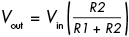
Figure 4-34: Reference voltage formula
In the formula, Vout is the reference voltage, and Vin is the input voltage—in this case, 5 V. R1 and R2 are the resistor values in ohms.
The simplest way to divide the voltage is to split Vin in half by setting R1 and R2 to the same value—for example, 10 kΩ each. When you’re doing this, it’s best to use the lowest-tolerance resistors you can find, such as 1 percent; confirm their true resistance values with a multimeter and use those confirmed values in the calculation. Furthermore, it’s a very good idea to place a 100 nF capacitor between AREF and GND to avoid a noisy AREF and prevent unstable analog readings.
When using an external reference voltage, insert the following line in the void setup() section of your sketch:
analogReference(EXTERNAL); // select AREF pin for reference voltageUsing the Internal Reference Voltage
The Arduino Uno also has an internal 1.1 V reference voltage. If this meets your needs, no hardware changes are required. Just add this line to void setup():
analogReference(INTERNAL); // select internal 1.1 V reference voltageThe Variable Resistor
Variable resistors, also known as potentiometers, can generally be adjusted from 0 Ω up to their rated value. Their schematic symbol is shown in Figure 4-35.

Figure 4-35: Variable resistor (potentiometer) symbol
Variable resistors have three pin connections: one in the center pin and one on each side. As the shaft of a variable resistor turns, it increases the resistance between one side and the center and decreases the resistance between the opposite side and the center.
Variable resistors can be either linear or logarithmic. The resistance of linear models changes at a constant rate as they turn, while the resistance of logarithmic models changes slowly at first and then increases rapidly. Logarithmic potentiometers are used more often in audio amplifier circuits, because they model the human hearing response. You can generally identify whether a potentiometer is logarithmic or linear via the marking on the rear. Most will have either an A or a B next to the resistance value: A for logarithmic, B for linear. Most Arduino projects use linear variable resistors, such as the one shown in Figure 4-36.

Figure 4-36: A typical linear variable resistor
You can also get miniature versions of variable resistors, known as trimpots or trimmers (see Figure 4-37). Because of their size, trimpots are useful for making adjustments in circuits, but they’re also very useful for breadboard work because they can be slotted in.

Figure 4-37: Various trimpots
Piezoelectric Buzzers
A piezoelectric element (piezo for short), or buzzer, is a small, round device that can be used to generate loud and annoying noises that are perfect for alarms—or for having fun. Figure 4-38 shows a common example, the TDK PS1240, next to an American quarter, to give you an idea of its size.

Figure 4-38: The TDK PS1240 piezo
Piezos contain a very thin plate inside the housing that moves when an electrical current is applied. When a pulsed current is applied (such as on . . . off . . . on . . . off), the plate vibrates and generates sound waves.
It’s simple to use piezos with the Arduino because they can be turned on and off just like an LED. The piezo elements are not polarized and can be connected in either direction.
Piezo Schematic
The schematic symbol for the piezo looks like a loudspeaker (Figure 4-39), which makes it easy to recognize.
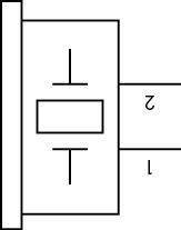
Figure 4-39: Piezo schematic symbol
Project #7: Trying Out a Piezo Buzzer
If you have a piezo handy and want to try it out, first connect it between Arduino GND and digital pins D3 to D0 inclusive. Then upload the following demonstration sketch to your Arduino:
// Project 7 - Trying Out a Piezo Buzzer
#define PIEZO 3 // pin 3 is capable of PWM output to drive tones
int del = 500;
void setup()
{
   pinMode(PIEZO, OUTPUT);
}

void loop()
{
1    analogWrite(PIEZO, 128);  // 50 percent duty cycle tone to the piezo
   delay(del);
   digitalWrite(PIEZO, LOW); // turn the piezo off
   delay(del);
}
This sketch uses pulse-width modulation on digital pin 3. If you change the duty cycle in the analogWrite() function (currently it’s 128, which is 50 percent on) at 1, you can alter the sound of the buzzer.
To increase the volume of your piezo, increase the voltage applied to it. The voltage is currently limited to 5 V, but the buzzer would be much louder at 9 or 12 V. Because higher voltages can’t be sourced from the Arduino, you would need to use an external power source for the buzzer, such as a 9 V battery, and then switch the power into the buzzer using a BC548 transistor as an electronic switch. You can use the same sketch with the schematic shown in Figure 4-40.
The part of the schematic labeled 12 V will be the positive side of the higher-power supply, whose negative side will connect to the Arduino GND pin.
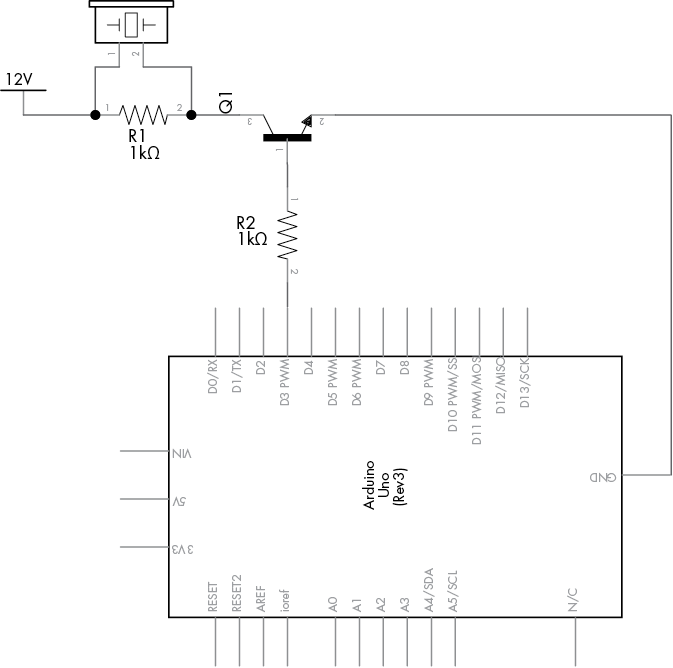
Figure 4-40: Schematic for Project 7
Project #8: Creating a Quick-Read Thermometer
Temperature can be represented by an analog signal. We can measure temperature using the TMP36 voltage output temperature sensor made by Analog Devices (http://www.analog.com/tmp36/), shown in Figure 4-41.

Figure 4-41: TMP36 temperature sensor
Notice that the TMP36 looks just like the BC548 transistor we worked with in the relay control circuit in Chapter 3. The TMP36 outputs a voltage that is proportional to the temperature, so you can determine the current temperature using a simple conversion. For example, at 25 degrees Celsius, the output voltage is 750 mV, and each change in temperature of 1 degree results in a change of 10 mV. The TMP36 can measure temperatures between −40 and 125 degrees Celsius.
The function analogRead() will return a value between 0 and 1,023, which corresponds to a voltage between 0 and just under 5,000 mV (5 V). If we multiply the output of analogRead() by (5,000/1,024), we will get the actual voltage returned by the sensor. Next, we subtract 500 (an offset used by the TMP36 to allow for temperatures below 0) and then divide by 10, which leaves us with the temperature in degrees Celsius. If you work in Fahrenheit, then multiply the Celsius value by 1.8 and add 32 to the result.
The Goal
In this project, we’ll use the TMP36 to create a quick-read thermometer. When the temperature falls below 20 degrees Celsius, a blue LED turns on; when the temperature is between 20 and 26 degrees, a green LED turns on; and when the temperature is above 26 degrees, a red LED turns on.
The Hardware
Here’s what you’ll need to create this project:
- Three 560 Ω resistors (R1 to R3)
- One red LED (LED1)
- One green LED (LED2)
- One blue LED (LED3)
- One TMP36 temperature sensor
- One breadboard
- Various connecting wires
- Arduino and USB cable
The Schematic
The circuit is simple. When you’re looking at the labeled side of the TMP36, the pin on the left connects to the 5 V input, the center pin is the voltage output, and the pin on the right connects to GND, as shown in Figure 4-42.

Figure 4-42: Schematic for Project 8
The Sketch
And now for the sketch:
// Project 8 - Creating a Quick-Read Thermometer

// define the pins that the LEDs are connected to:
#define HOT 6
#define NORMAL 4
#define COLD 2

float voltage = 0;
float celsius = 0;
float hotTemp = 26;
float coldTemp = 20;
float sensor = 0;

void setup()
{
   pinMode(HOT, OUTPUT);
   pinMode(NORMAL, OUTPUT);
   pinMode(COLD, OUTPUT);
}

void loop()
{
   // read the temperature sensor and convert the result to degrees Celsius
1    sensor = analogRead(0);
   voltage = ( sensor * 5000 ) / 1024; // convert raw sensor value to
                                       // millivolts
   voltage = voltage - 500; // remove voltage offset
   celsius = voltage / 10;  // convert millivolts to Celsius
   // act on temperature range
2    if ( celsius < coldTemp )
   {
      digitalWrite(COLD, HIGH);
      delay(1000);
      digitalWrite(COLD, LOW);
   }
3    else if ( celsius > coldTemp && celsius <= hotTemp )
      {
         digitalWrite(NORMAL, HIGH);
         delay(1000);
         digitalWrite(NORMAL, LOW);
      }
      else
      {
         // celsius is > hotTemp
         digitalWrite(HOT, HIGH);
         delay(1000);
         digitalWrite(HOT, LOW);
      }
}
The sketch first reads the voltage from the TMP36 and converts it to a temperature in degrees Celsius at 1. Next, using the if-else statements at 2 and 3, the code compares the current temperature against the values for hot and cold and turns on the appropriate LED. The delay(1000) statements are used to prevent the lights from flashing on and off too quickly if the temperature fluctuates rapidly between two ranges.
You can experiment with the thermometer by blowing cool air over it to lower the temperature or by rubbing two fingers over the TMP36’s body to generate heat.
Looking Ahead
And Chapter 4 comes to a close. You now have a lot more tools to work with, including digital inputs and outputs, new types of variables, and various mathematical functions. In the next chapter, you will have a lot more fun with LEDs, learn to create your own functions, build a computer game and electronic dice, and much more.